eschmann J1 User manual

J1,J2,J3 & J5
OPERATION TABLES
Service Manual
T-SM9e
699300
Service Manual
Preliminary
Technical data
Safety notes
Maintenance
Read these Instructions before use
Keepthese‘Instructions’in a safeconvenient placeforfuturereference.Readin conjunction
with the Publications detailed in Section 1.3..
Eschmann After Sales Service Department
The Eschmann After Sales Service Department is staffed and equipped to provide advice and
assistance during normal office hours.To avoid delays when making enquires, please quote the
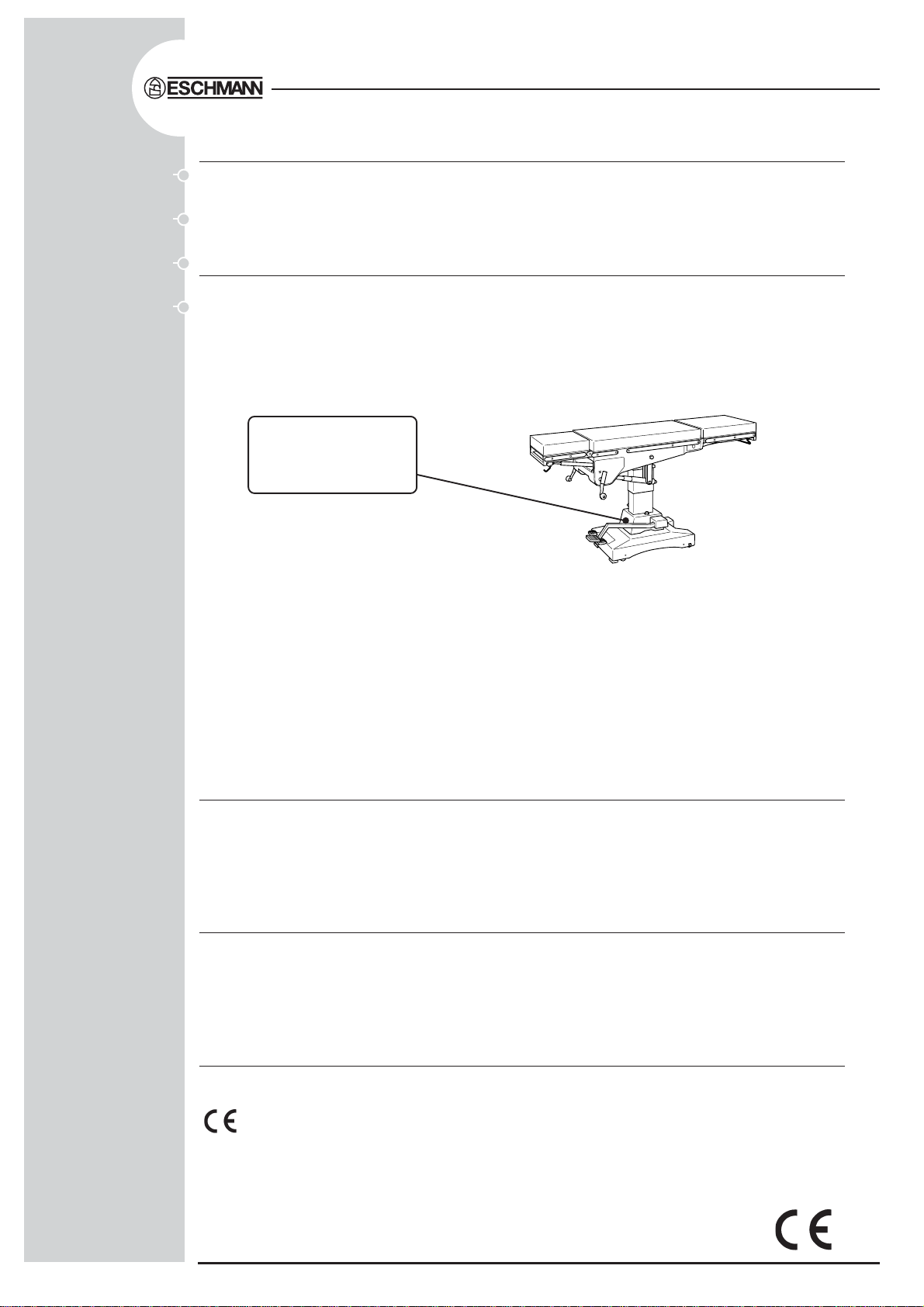
ModelandSerial NumberofyourOperationTablewhich isshown onthe SerialNumber plate,the
location of which is shown below. Please ensure you include all alpha and numeric digits of the
Serial Number.
All correspondence relating to the after sales service of Eschmann Equipment to be addressed to :
UK Customers
Eschmann Equipment,Peter Road, Lancing,West Sussex BN15 8TJ, England.
Tel: +44 (0) 1903 765040. Fax:+44 (0) 1903 762006.
Overseas Customers
Contact your local distributor. In case of doubt contact Eschmann Equipment.
Trade marks
The ESCHMANN logo is a registered trade mark of Eschmann Holdings Ltd.
”J1”,“J2”,”J3”and “J5” are trade marks of Eschmann Holdings Ltd.
Copyright © 2002
All rights reserved.This booklet is protected by copyright.No part of it may be reproduced, stored in a
retrieval system or transmitted in any form or by any means, electronic, mechanical, photocopying,
recording or otherwise without written permission from Eschmann HoldingsLimited.
The information in this publication was correct at the time of going to print. The Company, however,
reserves the right to modify or improve the equipment referred to.
If the CE mark is affixed to the product, it indicates compliance with Council Directive
93/42/EEC of 14 June 1993 concerning medical devices.
T-SM9e March 2002
The Serial Number
Plateislocated onthe
pedestalasindicated.

T-SM9e Page 3 of 26
J1 J2 J3 & J5 OPERATION TABLES
READ THESE INSTRUCTIONS BEFORE USE
KeeptheseInstructions in a safe convenientplaceforfuturereference.Readinconjunction
with the relevant Publications detailed in the preliminary information section.
Page
1. PRELIMINARY .. .. .. .. .. 4
2. TECHNICAL DATA .. .. .. .. 5
J1 Operation Table .. .. .. .. .. 5
J2 Operation Table .. .. .. .. .. 6
J3 Operation Table .. .. .. .. .. 7
J5 Operation Table .. .. .. .. .. 8
3. SAFETY NOTES .. .. .. .. .. 9
4. MAINTENANCE .. .. .. .. .. 10
General .. .. .. .. .. .. .. 10
Cleaning, disinfection, care and storage .. 10
Periodic lubrication, checks & adjustment .. 10
Base Components .. .. .. .. .. 10
Castors and wheels .. .. .. .. .. 10
Brakes and brake mechanism .. .. .. 10
Hydraulic cylinder .. .. .. .. .. 10
Gears .. .. .. .. .. .. .. 12
Trendelenburg .. .. .. .. .. 12
Lateral tilt .. .. .. .. .. .. 12
Hinge pin and nut .. .. .. .. .. 13
Lateral screw and nut .. .. .. .. 13
Trend. screw assembly friction collars .. 14
Head section .. .. .. .. .. .. 16
Leg section and catches .. .. .. .. 16
Fault diagnosis and remedies .. .. .. 16
Excessive lateral movement of table top.. 16
Inability to raise table top.. .. .. .. 16
Table top not maintaining height .. .. 17
Operation table will not lower .. .. .. 18
Removal & installation of components .. 20
Replacement of trend, screw .. .. .. 20
Replacing lateral tilt drive belt.. .. 20
Removing hydraulic cylinder from base .. 21
Replacing ram cup washer .. .. .. 21
Removing and cleaning ball valve .. .. 21
Page
Changing hydraulic oil .. .. .. .. 21
Replacing an antistatic wheel in base .. 22
Replacing castor .. .. .. .. .. 22
Replacing worn brake pad .. .. .. 22
Replacing brake quadrant.. .. .. .. 22
Replacing quadrant pinion .. .. .. 22
Replacing broken quadrant pillar .. .. 23
Replacing a control handle .. .. .. 23
Replace push-button catches (leg section) 23
Replacing release handle (head section) .. 24
Replacing release bar (leg section) .. .. 24
Replacing gas spring (head section,J1/2/3) 24
Replacing gas spring unit (leg section) .. 24
Replacing gas spring (head section, J5) .. 24
Hydraulic system operation notes .. .. 26
ILLUSTRATIONS
Fig.1 Ram key adjustment .. .. .. .. 10
Fig.2 Base assembly .. .. .. .. .. 11
Fig.3 Gearbox of J2 and J3 .. .. .. .. 12
Fig.4 Hinge pin and nut adjustment .. .. 13
Fig.5 Lateral screw and nut adjustment .. 13
Fig.6 Releasing trend. screw assembly .. 15
Fig.7 Trendelenburg screw assembly .. .. 15
Fig.8 Head (J1, J2 and J3) and leg sections.. 15
Fig.9 Removing hydraulic cylinder .. .. 17
Fig.10 Hydraulic cylinder assembly .. .. 18
Fig.11 Ram release mechanism .. .. .. 19
Fig.12 Drive belt replacement .. .. .. 20
Fig.13 Replacing a control handle .. .. 23
Fig.14 Catch mechanism for leg section .. 24
Fig.15 Removing release handle/bar and
gas spring unit .. .. .. .. .. 25
Fig.16 Head section J5, replacing gas
spring unit .. .. .. .. .. .. 25
Fig.17 Hydraulic system operation .. .. 26
CONTENTS

J1 J2 J3 & J5 OPERATION TABLES
Page 4 of 26 T-SM9e
1. PRELIMINARY INFORMATION
1.1 This Service Manual should be referred to for details of the J1, J2, J3 and the J5 general purpose,
three or four-section, mobile, operation tables, REF 80-820-14, 80-800-11, 80-810-26,
80-810-41, 80-830-10 (serial numbers JIAA8E0000, J2AA8E0000, J3AB8E0000, J3RB8E0000,
J4AB8E0000 respectively, or above).
1.2 Operation tables J1, J2 and J5 are similar. The J3 operation table is specially designed to meet
the needs of gynaecological procedures, in addition to its suitability as a general purpose table. The
differences between the J1, J2 and J5 tables, and the J3 table, are detailed in Part 7 of the Instructions
for Use.
1.3 Instruction and Service Manuals should be readily accessible for reference prior to and when
operating, cleaning and servicing the Operation Table. All manuals are available from Eschmann
Equipment, see inside front cover for address details.
Related Technical Publications:-
Instructions for Use - J1 J2 J3 and J5 Operation Tables - T-IM22
Illustrated Parts List - J1 J2 J3 and J5 Operation Tables - T-IPL8
1.4 J3 and J5 tables comply with BS6859 Part 1: 1987 (except for clause 7).
Part 1
T-SM9e Page 5 of 26
J1 J2 J3 & J5 OPERATION TABLES
135Kg
50Kg
150mm
50Kg
150mm
2. TECHNICAL DATA
JI OPERATION TABLE
DIMENSIONS
Width including sidebars .. .. 545mm
Overall length .. .. .. .. 1905mm
Minimum table height
without mattress .. .. .. 730mm
Maximum table height
without mattress .. .. .. 1073mm
SIDE-BAR DIMENSIONS
UK .. .. .. .. .. 32 x 6.5mm
North America .. .. .. 28.5 x 9.5mm
Europe .. .. .. .. .. 25 x 9mm
MOVEMENTS
Maximum Trendelenburg .. .. 45°
Maximum Reverse Trendelenburg .. 30°
Head section adjustment .. +40° -40°
Leg section adjustment .. ..+10° -100°
Table top rotation .. .. 360°
NET WEIGHT (approx) .. .. 196kg
X-RAY ATTENUATION
The X-ray attenuation of the top of this operation
table is equivalent to less than 0.5mm of 99.5%
pure aluminium.
OIL CAPACITY .. .. .. 2.8 litres
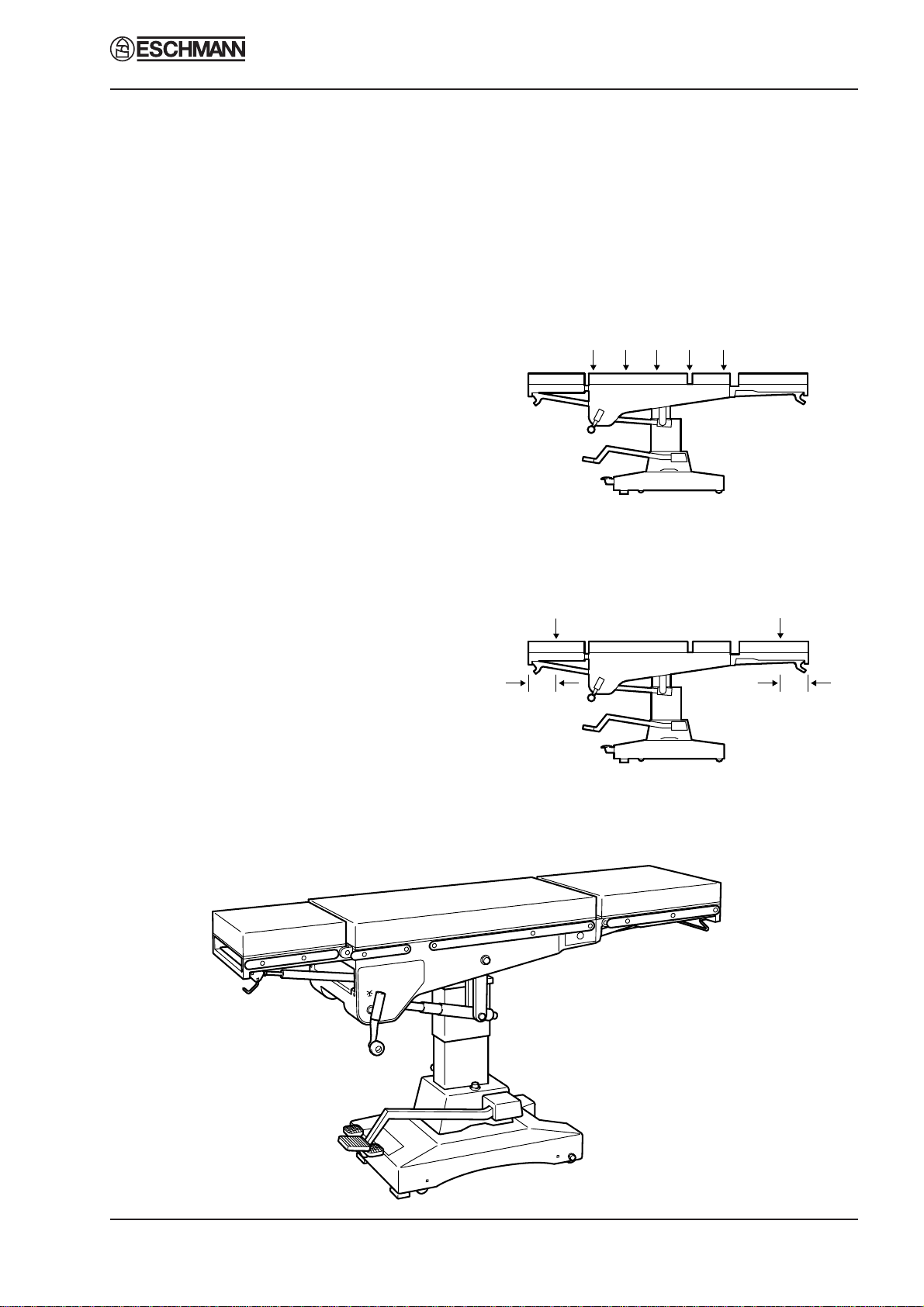
TABLE LOADING
RetentionofAdjusted Height: The table will retain
its adjusted height with a load of 135kg uniformly
applied to the trunk sections.
Longitudinal Deflection Load: The table will
withstandaloadof50kgappliedat a point 150mm
in from either end of the head or leg section.
Part 2
Also see the WARNINGS in Section 3, Safety
Notes (page 9) for stability information and
maximum loads for accessories.

J1 J2 J3 & J5 OPERATION TABLES
Page 6 of 26 T-SM9e
135Kg
50Kg
150mm
50Kg
150mm
2. TECHNICAL DATA
J2 OPERATION TABLE
DIMENSIONS
Width including sidebars .. .. 545mm
Overall length .. .. .. .. 1905mm
Minimum table height
without mattress .. .. .. 730mm
Maximum table height
without mattress .. .. .. 1073mm
SIDE-BAR DIMENSIONS
UK .. .. .. .. .. 32 x 6.5mm
North America .. .. .. 28.5 x 9.5mm
Europe .. .. .. .. .. 25 x 9mm
MOVEMENTS
Maximum Trendelenburg .. .. 45°
Maximum Reverse Trendelenburg .. 30°
Maximum Lateral Tilt .. .. .. +15° -15°
Head section adjustment .. +40° -40°
Leg section adjustment .. ..+10° -100°
Table top rotation .. .. 360°
NET WEIGHT (approx) .. .. 196kg
X-RAY ATTENUATION
The X-ray attenuation of the top of this operation
table is equivalent to less than 0.5mm of 99.5%
pure aluminium.
OIL CAPACITY .. .. .. 2.8 litres
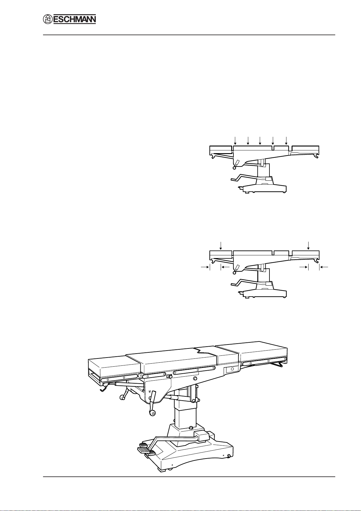
TABLE LOADING
RetentionofAdjusted Height: The table will retain
its adjusted height with a load of 135kg uniformly
applied to the trunk sections.
Longitudinal Deflection Load: The table will
withstandaloadof50kgappliedat a point 150mm
in from either end of the head or leg section.
Part 2
Oil filler cap
Also see the WARNINGS in Section 3, Safety
Notes (page 9) for stability information and
maximum loads for accessories.
T-SM9e Page 7 of 26
J1 J2 J3 & J5 OPERATION TABLES
135Kg
50Kg
150mm
50Kg
150mm
2. TECHNICAL DATA
J3 OPERATION TABLE
DIMENSIONS
Width including sidebars .. .. 545mm
Overall length .. .. .. .. 1905mm
Minimum table height
without mattress .. .. .. 730mm
Maximum table height
without mattress .. .. .. 1073mm
SIDE-BAR DIMENSIONS
UK .. .. .. .. .. 32 x 6.5mm
North America .. .. .. 28.5 x 9.5mm
Europe .. .. .. .. .. 25 x 9mm
MOVEMENTS
Maximum Trendelenburg .. .. 45°
Maximum Reverse Trendelenburg .. 45°
Maximum Lateral Tilt .. .. .. +15° -15°
Head section adjustment +/- 40°(-10° traversed)
Leg section adjustment .. .. ..+10° -100°
Table top rotation .. .. .. 360°
Table top lithotomy traverse
Head and trunk sections traverse
over perineal section
NET WEIGHT (approx) .. .. 196kg
X-RAY ATTENUATION
The X-ray attenuation of the top of this operation
table is equivalent to less than 0.5mm of 99.5%
pure aluminium.
OIL CAPACITY .. .. .. 2.8 litres
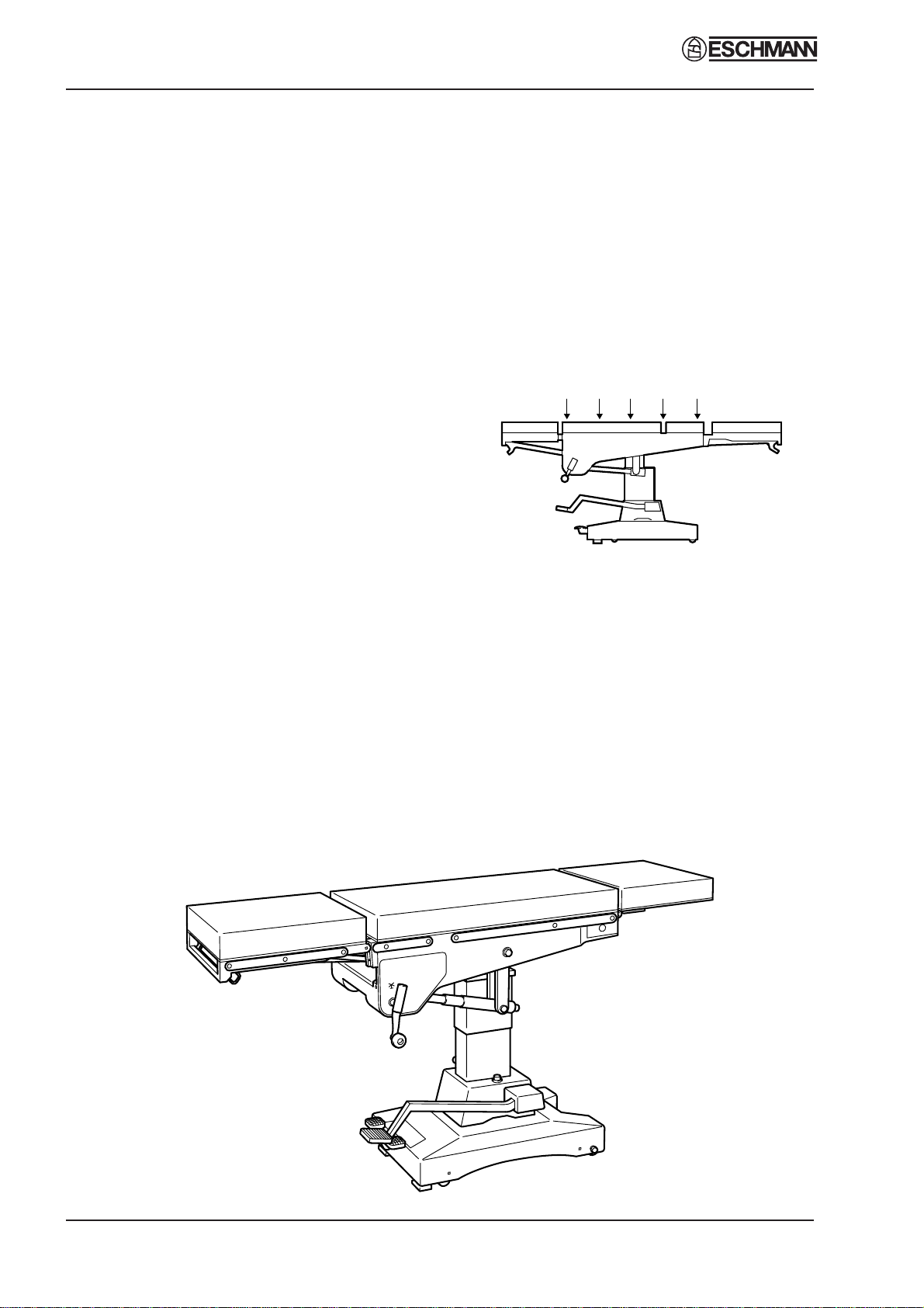
TABLE LOADING
RetentionofAdjusted Height: The table will retain
its adjusted height with a load of 135kg uniformly
applied to the trunk sections.
Longitudinal Deflection Load: The table will
withstandaloadof50kgappliedat a point 150mm
in from either end of the head or leg section.
Part 2
Also see the WARNINGS in Section 3, Safety
Notes (page 9) for stability information and
maximum loads for accessories.
J1 J2 J3 & J5 OPERATION TABLES
Page 8 of 26 T-SM9e
135Kg
2. TECHNICAL DATA
J5 OPERATION TABLE
DIMENSIONS
Width including sidebars .. .. 545mm
Overall length .. .. .. .. 1905mm
Minimum table height
without mattress .. .. .. 680mm
Maximum table height
without mattress .. .. .. 1020mm
SIDE-BAR DIMENSIONS
UK .. .. .. .. .. 32 x 6.5mm
North America .. .. .. 28.5 x 9.5mm
Europe .. .. .. .. .. 25 x 9mm
MOVEMENTS
Maximum Trendelenburg .. .. 45°
Maximum Reverse
Trendelenburg 30°(10° withtable lowered)
Head section adjustment .. .. +40° -40°
Leg section adjustment .. .. .. +10° -75°
Table top rotation .. .. 360°
NET WEIGHT (approx) .. .. 196kg
X-RAY ATTENUATION
The X-ray attenuation of the top of this operation
table is equivalent to less than 0.5mm of 99.5%
pure aluminium.
OIL CAPACITY .. .. .. 2.8 litres
TABLE LOADING
RetentionofAdjusted Height: The table will retain
its adjusted height with a load of 135kg uniformly
applied to the trunk sections. (Note. Graphic is
indicative only, for J5 sections see main graphic at
foot of page).
Longitudinal Deflection Load: The table will
withstandaloadof50kgappliedat a point 150mm
in from either end of the head section.
The maximum load for the leg section is 30kg.
Also see the WARNINGS in Section 3, Safety
Notes (page 9) for stability information and
maximum loads for accessories.
Part 2

T-SM9e Page 9 of 26
J1 J2 J3 & J5 OPERATION TABLES Part 3
DO:
♦Keep the instruction manual close-to-hand.
♦Read the instructions carefully before using
the table.
♦Check that the leg section is secure, and put
the table base in the brake position before
use.
♦Lower the table top fully before washing the
table.
♦Readandfollowtheinstructionsforcleaning,
and for the care of the mattresses and pads.
♦Use the correct mattress and accessories.
♦Service the table and accessories regularly.
♦Remove table accessories and their clamps,
in particular rotary clamps from side bars,
when they are not in use.
3. SAFETY NOTES
Attention to the following points will prolong the life and efficiency of your operating table and
will help to avoid the risk of accidents, or damage:
DO NOT:
♦Lift the table by its top.
♦Push the table over rough surfaces, use a
trolley.
♦Drop the table (or individual sections) when
transporting it.
♦Put heavy weights on the table sections.
♦Put sharp objects on, or against mattresses,
pads, or the radiographic table top.
♦Drop heavy objects onto the radiographic
top.
♦Spill oil, ether, or other chemical fluids onto
the mattress or the pads.
♦Pull the table by the head or leg section,
always push it.
♦Exceed maximum table loading
WARNINGS
The J Series of Operation Table have been designed to minimise the possibility of accidental
electrosurgery burns. Contact with any metal surfaces (e.g. table side bars, or other equipment
etc.) can cause burns during electrosurgery and must be avoided.
The J Series of Operation Table have been designed for patients weighing up to 135kg with their
centre of gravity (normally the perineum) over the base. However patient positioning and
additional loads can compromise table stability. Ensure that loading does not compromise table
stability.
With the table in (or during transition into) the castor position, the centre of gravity of the
patient (normally the perineum) should lie over the centre of the column. Whenever this is not
practical the overhanging weight of the patient and table should be adequately supported (e.g.
by at least two able people). Take extreme care when moving a table with a patient on and
ensure that the table is at minimum height
The patient’s weight should be supported whenever the sections are adjusted or removed from
the table during re-positioning.
The head and leg sections are designed to support and position the appropriate part of the
patient’s weight only. Damage leading to failure of the section may be caused if excessive weight
is applied.
Themaximum loading weightof 10kg mustnot be exceededfor the Detachableophthalmic head
flap and the Non-Detachable head flap accessories, as this may cause damage to the accessory
and could result in injury to the patient.
It is necessary to check at regular intervals for wear, corrosion, material fatigue and ageing on
allaccessories whichsupport all orpart of thebody of thepatient using asingle gas-spring. Such
accessories are the detachable ophthalmic head flap and the divided leg section.

J1 J2 J3 & J5 OPERATION TABLES
Page 10 of 26 T-SM9e
4. MAINTENANCE
GENERAL
4.1 The information provided in this Service
Manual falls into four categories:
♦ Cleaning, Disinfection, Care and Storage.
♦ Periodiclubrication,checksandadjustments
♦ Fault diagnosis and remedies
♦ Removal and installation of components
CLEANING, DISINFECTION, CARE AND
STORAGE
4.2 For Cleaning, Disinfection, Care and
Storage instructions refer to Section 8 of the
InstructionsforUse(PublicationT-IM22,alsosee
section 1.3).
PERIODIC LUBRICATION, CHECKS
AND ADJUSTMENTS
Base Components (Fig. 2)
4.3 Inorderto carry outmaintenanceprocedures
to the table base, it is necessary to tilt the table on
its side and expose the underside of the base.
Proceed as follows:
i Removethelegsectioninthenormalmanner.
ForJ3 tableremovealso theperineal section
and traverse the table top (see Instruction
Manual, Publication No. T-IM22).
ii Raise the table top to its maximum height.
iii Placeananaesthetist’sstool,orsimilarstrong
support, alongside the table.
iv Placethebrakepedalinthe‘castor’position.
v Stand on the same side of the table as the
support but with the pump lever on the
opposite side. Push the table away about
30 cmandthenpullitback.This ensuresthat
all the castors are pointing away from the
operator.Twopeople on the same side of the
tableasthesupport(oneateachend)cannow
each place a foot against the base and lever
the table over gently, lowering it onto the
support.
Castors and wheels (Fig. 2)
4.4. Clean each castor and wheel free of debris,
then lubricate the castor and wheel ball races with
a light machine oil (or WD40 aerosol lubricant).
Part 4
Brakes and brake mechanism (Fig. 2)
4.5. Check the action of the brake mechanism
and also check for wear on the brake pads, broken
brake pinion or quadrant teeth and play in the
quadrant taper pins. Check stop screws for wear.
To replace quadrant see section 4.39; to replace
quadrant pinion, see section 4.40.
4.6 Fit new brake pads where necessary,
referring to section 4.38.
Hydraulic Cylinder (Fig. 1)
4.7 Raise the table top to its maximum height,
then depress the height adjustment (hydraulic
pump) pedal fully and check for smoothness and
rate of descent.
Fig. 1 Ram key adjustment
4.8 Raise the table top to its maximum height
again and release the ram cover securing screws
at the top. Lower the 3-section telescopic cover
(1) to expose the ram (2) and ram key (3).
4.9 Remove the ram key, clean out keyway and
refit key.
4.10 Examineramsurfaceforrustand, if present,
cleanoff with fine emery cloth. Lubricate exposed
surface of ram. Seal the top of the cylinder with
cloth wound round the ram to prevent damage if
using emery cloth.
4.11 Before refitting ram cover, check that table
will raise and lower smoothly. If this is not the
case, the ram key is probably secured too tightly.
Release the key attachment bolts (4) slightly to
remove excessive friction, then retighten.
T-SM9e Page 11 of 26
J1 J2 J3 & J5 OPERATION TABLES Part 4
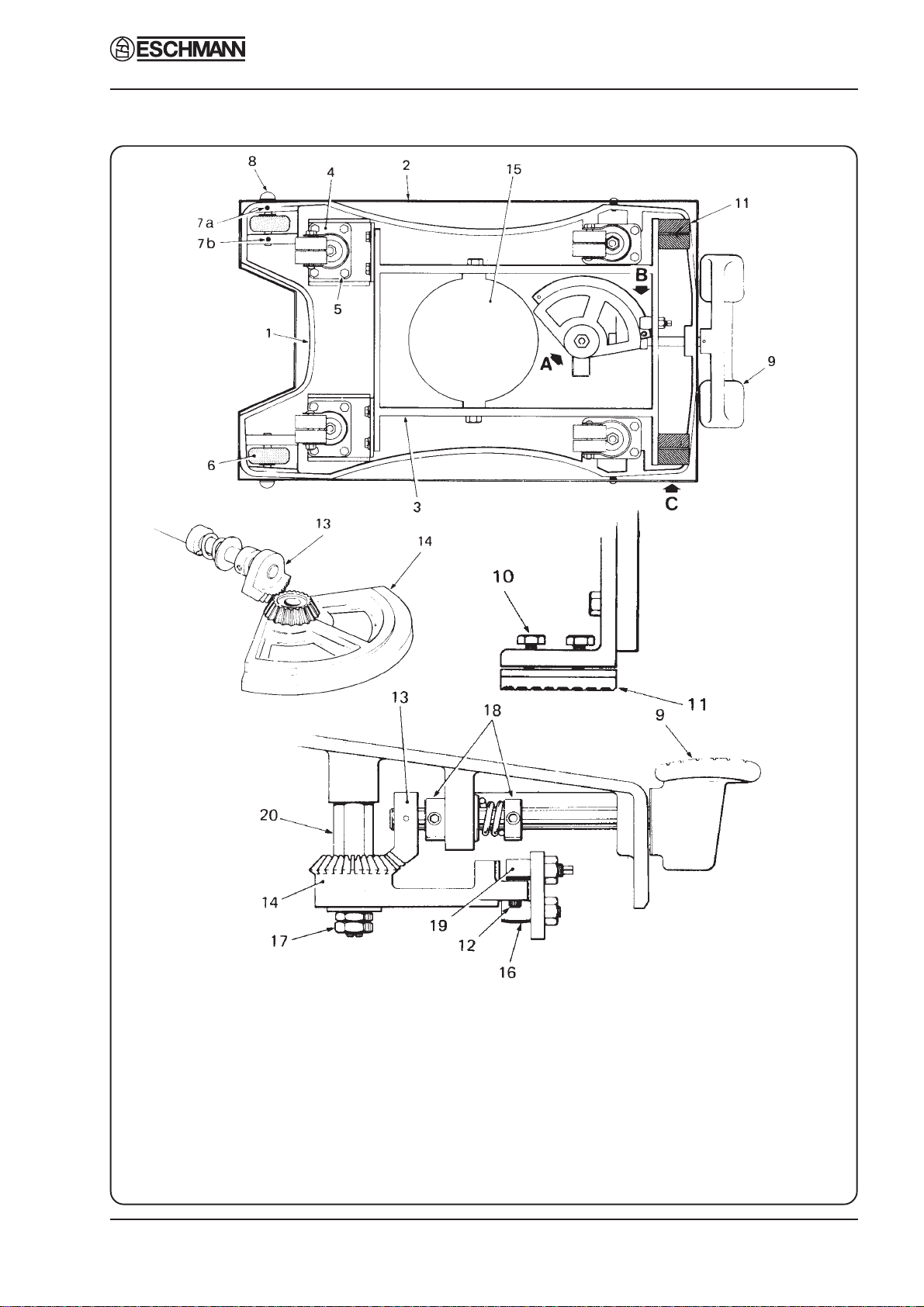
Fig. 2 Base assembly
1. Base casting 8. Wheel spindle 15. Oil sump
2. Base cover 9. Base control pedal 16. Roller
3. Castor frame 10. Brake pad screws 17. Quadrant securing nuts
4. Castor 11. Brake pad 18. Brake shaft collars
5. Castor mounting screw12. Stop screw 19. Eccentric pin
6. Wheel 13. Pinion 20. Quadrant pillar
7a/b. Grub screws 14. Quadrant
DETAIL A
DETAIL C
DETAIL B
4. MAINTENANCE

J1 J2 J3 & J5 OPERATION TABLES
Page 12 of 26 T-SM9e
Part 5Part 4
4.12 Check for signs of oil leaks. If table will
not pump to its full height, refill reservoir with
the Eschmann oil supplied with the table, in small
measures, lowering the table after each addition.
This will avoid the risk of introducing too much
oil into the hydraulic system.
Gears (Fig. 3)
4.13 Remove socket head screws (1) and lift
away gearbox cover (2). Proceed to examine gear
operation as follows:
Trendelenburg (J1, J2, J3 and J5 tables)
4.14 Check operation of the Trendelenburg
control handle (3) and ensure that full table top
movement is achieved in both directions, with the
table top raised from its lowest position (see
Technical Data). Check also that the two grub
4. MAINTENANCE
1. Gearbox cover screws
2. Gearbox cover
3 Trendelenburg control handle
4 Trendelenburg gear housing
5. Trendelenburg screw shaft
6. Lateral tilt control handle
7. Lateral tilt drive belt screw
8. Lateral tilt drive belt
9. Lateral screw
10. Lateral screw nut
Fig. 3 Gearbox of J2 and J3 operation tables
(J1 and J5 table similar, without lateral tilt)
screws (4) Fig. 7, securing screwed bush to bush
housing are sufficiently tight and that the friction
collar adjustment on the Trendelenburg screw
shaft is satisfactory. Check tightness of pivot bolt
(2)Fig. 6. If friction collar needs adjustment, refer
to section 4.18.
Lateral Tilt (J2 and J3 tables only)
4.15 Check operation of the lateral tilt control
handle(6)andensurethatfulltabletopmovement
isachievedin both directions (seeTechnicalData).
The lateral screw is driven by a toothed rubber
drive belt (8). The condition and tightness of the
drive belt should be examined periodically. If the
drive belt is damaged or has become stretched
(lack of positive movement when operating
control handle) the belt will need to be replaced
(refer to section 4.30). An examination to check

T-SM9e Page 13 of 26
J1 J2 J3 & J5 OPERATION TABLES Part 4
4. MAINTENANCE
for play in the table top will indicate whether or
not there is any need to adjust tightness of the
hinge pin and nut (see section 4.16) or the lateral
screw and nut (see section 4.17).
Hinge pin and nut (Fig. 4)
4.16 Pull table top as shown in Fig. 4 to check
for excessive play in the direction of the arrows.
If there is excessive play present, check to see if
hinge nut (1) and bolt (2) are loose. If so, * tighten
hinge nut (1) against hinge bolt (2) sufficiently to
take up the slackness. To do this, Eschmann
recommend using two short lengths of 3/16 in.
diameter round bar (3) inserted in the nut sockets,
as illustrated in Fig. 4 and applying an improvised
tommy bar (4) to turn the nut.
*Note: This could also indicate play in
Trendelenburggear.Ifthisisthecasethe complete
Trendelenburg screw assembly must be replaced.
For removal procedure, see section 4.18.
Sectional view in direction ‘A’
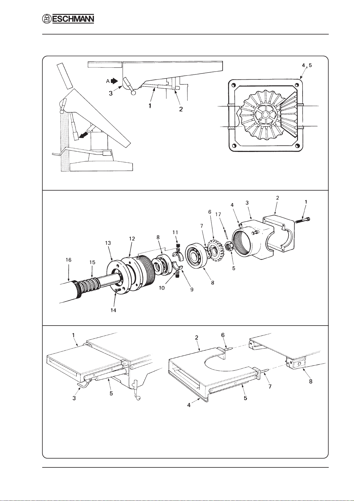
Fig. 4 Hinge pin and nut adjustment
Lateral screw and nut (Fig. 5)
4.17 Place table top in reverse Trendelenburg
position, then select Lateral Tilt and operate
control handle to test movement is satisfactory.
Pull as shown in Fig. 5. If undue play is suspected
proceed as follows:
i Checksecurenessoflink pivotsetscrews (6)
and (7).
ii Check secureness of grub screw on yoke (5)
which locks lateral screw bearing.
CAUTION: Do not over-tighten.
Detail ‘A’ Detail ‘B’
Fig 5 Lateral screw and nut adjustment
iii Finger testing at the point where the lateral
screw (1) passes through the nut (2) will
establish the need for the nut adjustment.
Firsttrytighteningsocketheadscrews(3)on
nut. If excessive play is still present, shim
removalwillbenecessary.Proceedasfollows:
(a) Unfasten socket head screws (3) on nut
and extract shim pack (4).
(b) Remove shims (0.002 in thickness per
shim, approx.) one at a time until play
is just taken up on re-tightening.

J1 J2 J3 & J5 OPERATION TABLES
Page 14 of 26 T-SM9e
Part 4
Trendelenburg screw assembly friction
collars (Fig. 6 and 7)
NOTE: Sections 4.18 and 4.19 should only be
referred to for tables with serial numbers
preceding those detailed below, for later tables or
tables that have had the latest Trendelenburg
screws fitted refer to section 4.20.
Tables with serial numbers as detailed (or above)
have the latest Trendelenburg screw fitted:-
J1 - 2198 J2 - 1314
J3 - 0440 J5 - 3080
4.18 Check adjustment of friction collars on
Trendelenburg screw. If the table does not easily
stay in Trendelenburg or reverse Trendelenburg
position, but tends to slip down under patient’s
weight, this indicates that the Tufnol friction
collars (9) Fig. 7 need tightening. Proceed as
follows:
i Remove the leg section as described in the
Instruction Manual and then pump the table
top to maximum height with the height
adjustment pedal.
ii Elevate the head section to the maximum
raised angle and place the table in maximum
reverse Trendelenburg position.
iii Remove the gearbox cover (3) Fig. 6
iv Bolster the table top in position as shown in
Fig. 6 and then free the lower end of the
Trendelenburg screw assembly (1) Fig. 6 by
removing the pivot screws (2) Fig. 6.
v Pivot the Trendelenburg screw assembly
aboutits bevelgear housing(4) Fig.6togain
access, in turn, to the four screws (5) Fig. 6
holdingthetwohalvesofthehousingtogether.
Remove the four screws to separate the two
halfhousingsandremovetheTrendelenburg
screw assembly, with the bevel gear lower
half housing from the table.
vi Refer to Fig. 7. Mark the bevel gear lower
halfhousing(3)andscrewedbush(12) toaid
reassembly, then remove socket head grub
screws(4)fromthehalfhousingandunscrew
the screwed bush (12) until heads of friction
collar grub screws (11) are exposed.
4. MAINTENANCE
vii Tighten grub screws (11), securing friction
collars (9), to a torque of 16 to 17 lbf in.
viii Screwscrewedbush(12)intothehalfhousing
and secure with socket head grub screws (4).
ix Using a suitable torque wrench, attached to
nut (17), check final friction of screw shaft
(15); the torque required to turn screw shaft
(15) should be between 30 and 35 lbf in. If
final friction torque cannot be achieved,
furthertighteneachfrictioncollargrubscrew
(11), by 1 to 2 lbf in. per occasion until 30 to
35 lbf in. torque is achieved. If torque figure
is not achieved by a maximum setting of 20
lbf in. then refer to section 4.19.
4.19 If further friction cannot be obtained by
carrying out the above procedure, the friction
collars are worn and a new Trendelenburg screw
assembly should be fitted. Refer to section 4.29
under REMOVAL AND INSTALLATION OF
COMPONENTS.
4.20 For tables having the latest design of
Trendelenburg screw assembly (see note
preceding 4.18) check the adjustment of the
friction collar on the Trendelenburg screw. If the
table does not easily stay in Trendelenburg or
reverse Trendelenburg position, but tends to slip
down under patient’s weight, this indicates that
the friction collar needs adjusting. Proceed as
follows:
i Remove the leg flap.
ii Unscrew and remove the end cap tubes from
the Trendelenburg screw assembly.
iii Using torque screwdriver (Part No. 759581
set to 20-25 lb.in. and fitted with adaptor
T2095 and 20mm socket), check the setting
by locating socket over the hexagon on the
end of the leadscrew and turning the torque
screwdriver.
iv If the leadscrew rotates before the torque
screwdriver reaches 20-25 lb.in. the friction
collar requires adjusting as (v) below. If the
leadscrew does not rotate the friction collar
setting is correct and requires no further
adjustmentandthetablecanbereassembled.
v Adjust the friction collar by slackening the
T-SM9e Page 15 of 26
J1 J2 J3 & J5 OPERATION TABLES Part 4
4. MAINTENANCE
View on Trendelenburg screw bevel
gear - half cover removed.
Fig. 6 Releasing Trendelenburg screw assembly
Fig. 7 Trendelenburg screw assembly
Fig. 8 Head (J1, J2, and J3) and leg sections
1. Head section
2. Leg section
3. Release handle
4. Release bar
5. Gas spring
6. Locking pin
7. Guide pin
8. Push-button catch
(See note preceding
section 4.18)

J1 J2 J3 & J5 OPERATION TABLES
Page 16 of 26 T-SM9e
Part 4
singlegrubscrewthatlocksthetorqueadjuster
nut and removing the three screws securing
thecapring located attherearof the gearbox
housing thus exposing the torque adjusting
nut. Locate spanner (tool number T2097)
onto the torque adjuster nut and tighten or
slacken to gain the correct setting (i.e. the
torque setting is above that given in (iii)
above but operation of the Trendelenburg
handle is not too difficult).
vi Replace the cap ring and secure using the
three screws, lock the torque adjuster nut by
tightening the single grub screw and
reassemble the table.
Head section J1, J2 & J3 (Fig. 8), J5 (Fig.16)
4.21 Proceed as follows:
i Test the action of the release handle and gas
spring. If the gas spring support is
unsatisfactory(headsectionfailstomaintain
its position) the complete gas spring unit
must be replaced, they cannot be serviced
(see section 4.50 for J1-J3 and section 4.52
for J5, noting warnings). Also seepage of
fluid indicates a failing unit.
CAUTION
Gas springs MUST NOT be
additionally lubricated.
ii Examinetheradiographictoppanelforsigns
of any damage (e.g. cracks or chips).
Leg section and catches (Fig. 8 and 14)
4.22 Proceed as follows:
i Remove the leg section, then clean out any
collected debris from the recesses of the
lockingand guidepinpush-button catchesin
thetrunksectionofthetableandlubricatethe
catch mechanism. Test the action of both
catches (see section 4.43).
ii Check spring loaded nylon plungers (2)
Fig. 14 for smooth action (see section 4.44).
iii Check tightness of pivot screws.
iv Cleanandlubricatelockingpin(6)Fig.8and
guide pin (7) Fig. 8 with a light machine oil.
v Check to make sure that locking pin and
guidepin securingscrews(at therearof each
pin) are securely tightened.
vi Refit leg section and test the action of the
release bar and gas springs. If the support of
either or both gas springs is unsatisfactory
(leg section will not maintain its position or
tends to sink to one side) the complete gas
spring unit(s) must be replaced; these items
can not be serviced (see section 4.51). Also
seepage of fluid indicates a failing unit.
CAUTION
Gas springs MUST NOT be
additionally lubricated.
vii Finally,examinethedetachableradiographic
toppanelforsignsofanydamage(e.g.cracks
or chips) and check that the securing spring
collars of the radiographic top are not
damaged.
FAULT DIAGNOSIS AND REMEDIES
Excessive lateral movement of table top (Fig.1)
4.23 Lateral movement of the table top is
controlled by the tapered ram key (3). Excessive
movementisdueto wear of the ramkeyincreasing
the clearance in the keyway. This can be corrected
by slightly loosening the ram key clamping bolts
(4), gently tapping the key into the keyway until
excess movement has been removed and
retightening the clamping bolts. Check that the
ram key has not been over-tightened by fully
raising and lowering the table top. If the table top
will not raise or lower correctly, the ram key has
been over-tightened and must be slackened until
normal raising and lowering of the table top can
be achieved.
Inability to raise table top (Fig. 9 and 10)
4.24 If normal operation of the height control
pedal fails to raise the table with the pedal
travelling through its full stroke, the fault is
probably due to the presence of dirt in the ball
valve, (1) Fig. 10 of the hydraulic cylinder. It is
often possible to clear this obstruction by
vigorously operating the height control pedal. If
4. MAINTENANCE
T-SM9e Page 17 of 26
J1 J2 J3 & J5 OPERATION TABLES Part 4
4. MAINTENANCE
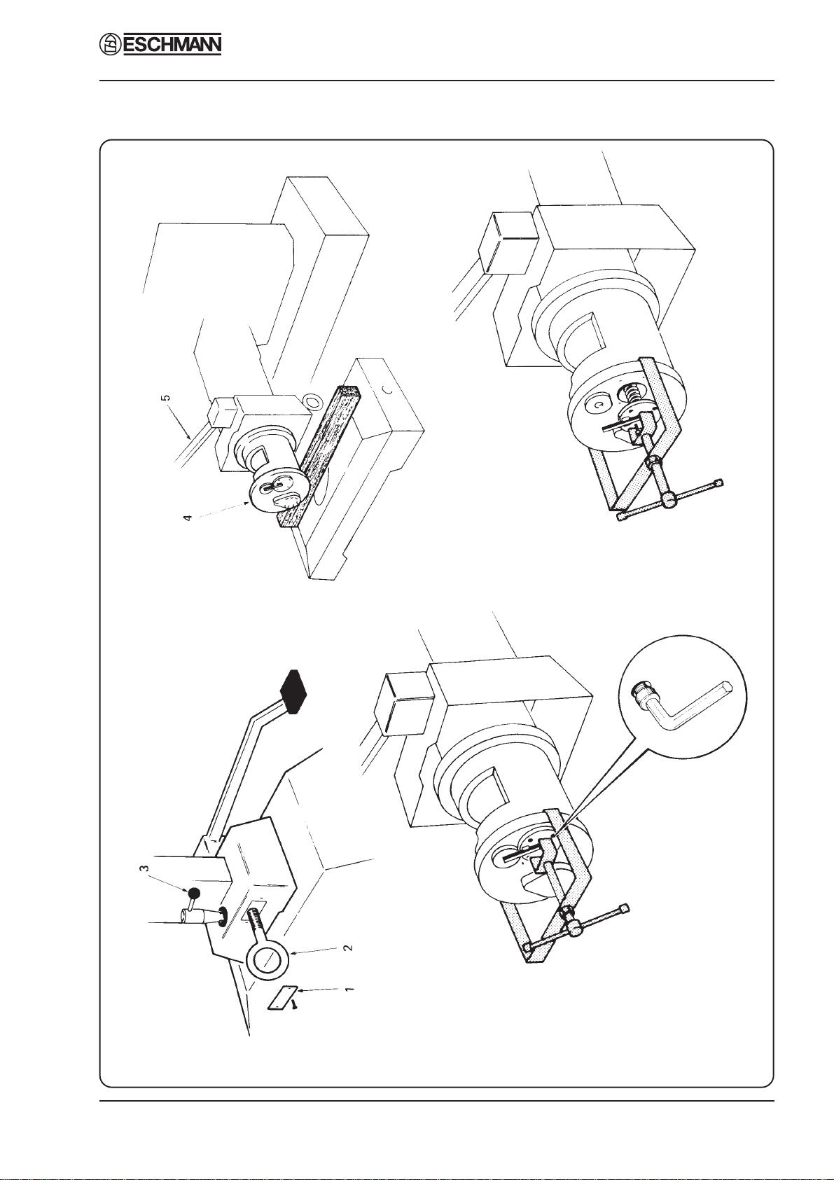
Fig. 9 Removing hydraulic cylinder from table base
(A) (B)
(C) (D)
J1 J2 J3 & J5 OPERATION TABLES
Page 18 of 26 T-SM9e
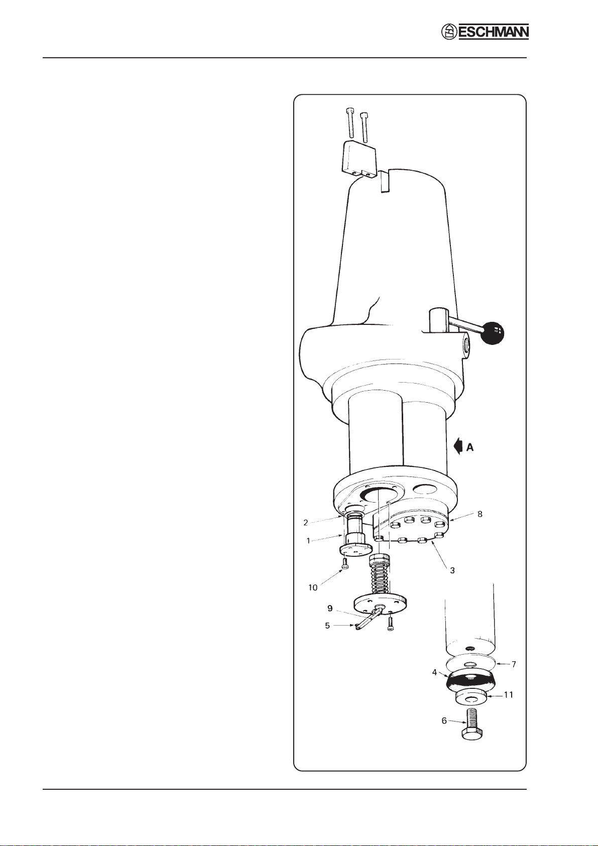
Fig. 10 Hydraulic cylinder assembly
Part 4
this fails, remove hydraulic cylinder from base
(see section 4.31); the ball valve should then be
disassembled and cleaned (see section 4.33). If
the pedal is suddenly inoperable either when
raising or lowering the table, refer to section 4.26.
Table top not maintaining height (Fig. 9 & 10)
4.25 If table top fails to maintain height, raise it
to its maximum height, fully depress the height
control pedal and, by pressing on the table top,
force the table top downwards as quickly as
possible. Repeat this operation several times. If
this does not rectify the fault remove hydraulic
cylinderfrombase(see section 4.31) thenexamine
the hydraulic mechanism for:
a) Condition of ball valve jointing washer (2)
Fig.10.Iffaulty,replaceit(seesection4.33).
b) Secureness of ram cover plate (3) Fig. 10. If
it is loose, re-tighten it.
c) Efficiencyofballvalve(1)Fig.10.Ifblocked
or jammed, disassemble and clean it, (see
section 4.31). If the seating of the larger
(spring-loaded) ball has been damaged,
replace the complete valve.
d) Condition of ram cup washer (4) Fig. 10. If
wornorchipped,replaceit(seesection4.32).
Operation table will not lower (Fig. 9 and 11)
4.26 Firstexaminethesteelramforrust(seenote
below); a type of black rust not easily noticed can
form on the circumference of the ram. This can
be identified by rubbing a piece of emery paper
on any discoloured portion of the ram surface. If
rust is detected, it must be removed completely,
as follows:
NOTE: Tables with serial numbers above those
given here have a black coating which prevents
this rust occurring, J1 - 2172, J3 - 1295, J3 - 0590,
J5 - 3059.
i Protectthetopofthecylinderbytyingapiece
of rag around the ram.
ii Cleantheramsurfacethoroughlybyrubbing
hard with emery paper.
iii Carefully clean off all particles of grit and
completely cover the exposed ram surface
with oil.
4. MAINTENANCE
T-SM9e Page 19 of 26
J1 J2 J3 & J5 OPERATION TABLES Part 4
4. MAINTENANCE
iv Test the raising and lowering movement of
the table top.
4.27 If on testing the table pump mechanism for
normal function it is found to be still inoperable
this may be due to the fact that efforts made to
lower the table while seized have strained the
pump lever driving pin or the ram release
mechanism. If the table top descends at all in
responseto pump lever operation, the descent will
be sluggish. To remedy this the following
procedure should be carried out:
i Refer to section 4.31 and remove hydraulic
cylinder from table base.
ii Examination of the ram release movement
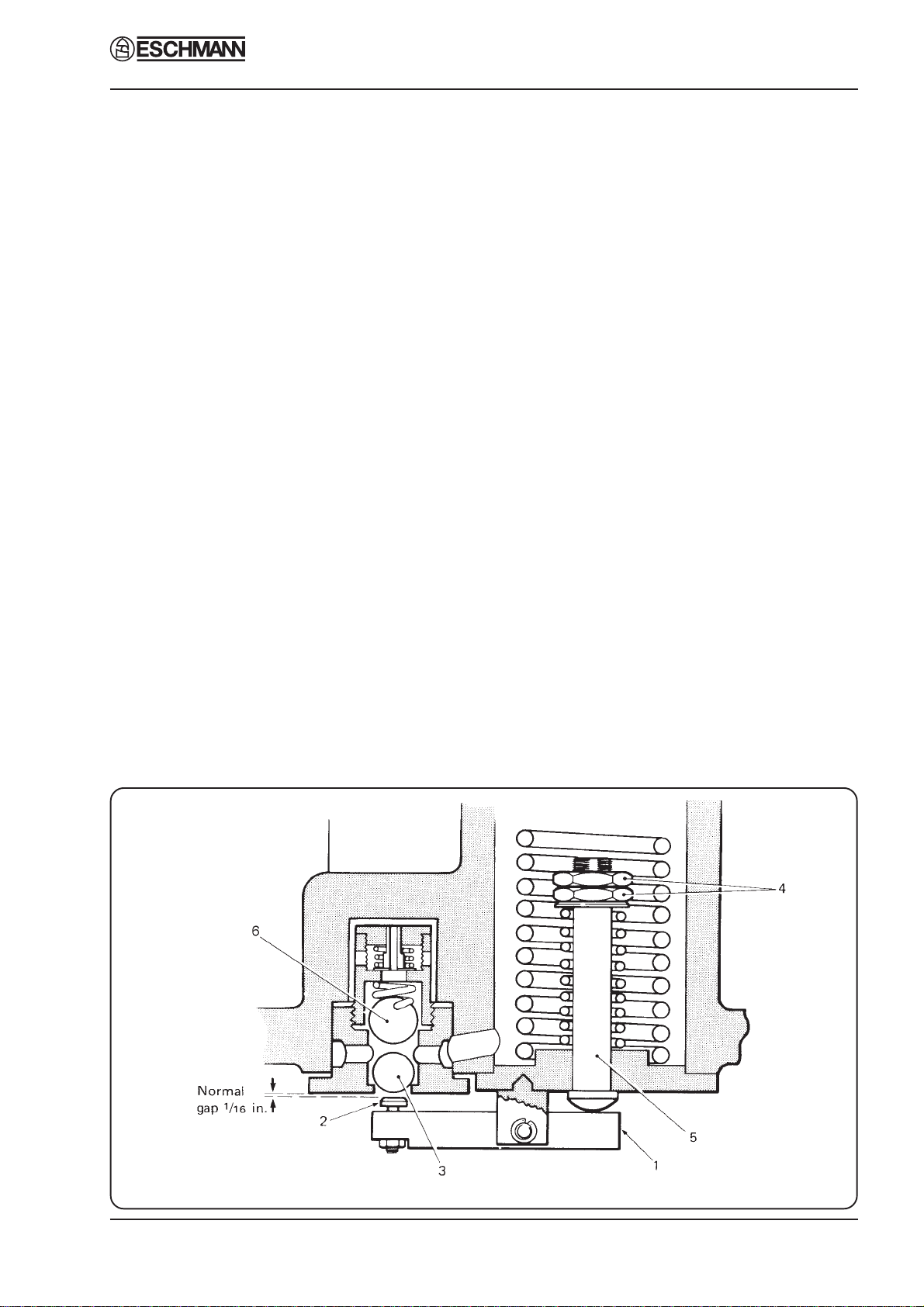
must now be carried out. Refer to Fig. 11.
When the pump lever is depressed fully, this
operates the ram release lever (1). The ram
release lever pivots and the release screw (2)
enterstheballvalve and should liftthelower
ball (3) at the end of lever travel. Before
testing this movement, the pressure in the
ballvalveshouldbeovercomebyforcingthe
releaseleverintotheballvalveaftercovering
the cylinder with a cloth to avoid leakage of
oil under pressure.
iii Nowdepressthepumpleverfullyandholdin
this position. Test the ram release lever by
tryingthemovementusingthumbpressure.If
the movement is other than very slight,
adjustment is required.
4.28 To adjust ram release mechanism, proceed
as follows:
i Positionthecompressiontoolclamp(included
in the tool kit available for the MR series
tables) across the base of the cylinder (see
Fig. 9(c)) and lightly tighten it onto the ram
release. Use an Allen key to remove the four
screws holding the ram release in position.
ii Loosen the clamp until oil starts to run from
the hole. Allow the oil to drain.
iii Continue to unscrew the clamp until
completelyloosethenremoveclampandram
release (see Fig. 9(d)).
iv Refer again to Fig. 11. Adjustment consists
of unscrewing, in a clockwise direction, the
two large lock nuts (4) on the end of the
release plunger (5) to allow more movement
of the ram release lever. This is in order to
cause the ball of the ball valve to be lifted
further and so release the table ram. (For a
more detailed explanation of the hydraulic
system, refer to section 4.53 and 4.54).
Note: This adjustment can only be made on a
trialanderrorbasis.Eachtimeanadjustment
Fig. 11 Ram release mechanism - adjustment

J1 J2 J3 & J5 OPERATION TABLES
Page 20 of 26 T-SM9e
Part 4
is made the ram release must be refitted into
thecylinderandthepumplevertriedandheld
to ascertain whether the release screw on the
lever projects too far into the ball valve, or
stillnotenough. Care mustbetaken to adjust
this correctly as strain will occur either side
ofthenormal. Asaguide, the normal setting
is 1/16in between release screw and ball
valve housing (approximately the thickness
of an engineer’s steel ruler).
v When the correctadjustmenthasbeenmade,
liftthecylinderandtabletopbodilyandguide
the cylinder back into the well of the base.
DO NOT ALLOW THE CYLINDER TO
DROP INTO THE BASE. When the table is
in an upright position and before lowering it
intothebase,refitthelockinglever.Thiswill
prevent the escape of oil from the cylinder.
The table top should now raise and lower
normally.
Note: If it is found that the driving pin of the
pump pedal has been bent - too badly for any
adjustment-anewpumplevermustbefitted.
4. MAINTENANCE
REMOVAL AND INSTALLATION OF
COMPONENTS
Replacement of Trendelenburg screw (Fig. 6
and 7)
4.29 To replace theTrendelenburg screw, remove
the old Trendelenburg screw assembly from the
operation table as detailed in 4.18. Fit a new
Trendelenburg screw assembly (latest style see
note in 4.18) and adjust it to the correct torque
setting as detailed in section 4.20. Reassemble the
table.
Note: The bevel gear housing has one thick and
one thin side wall. The thin side wall should
befittedroundtheneckofthegearshaftbevel
gear.Ensurethattheupperbevelgearhousing
is orientated to match before attempting to
refit the cap head screws securing the two
halves of the housing together.
Replacing lateral tilt drive belt (Fig. 3
and 12) - J2 and J3 tables only
4.30 If, on examination of the lateral tilt gear
drive belt, it appears that the belt needs replacing,
proceed as follows:
Fig. 12 Drive belt replacement
This manual suits for next models
3
Table of contents
Other eschmann Medical Equipment manuals


Popular Medical Equipment manuals by other brands

ActivePure
ActivePure Medical Guardian manual

Orliman
Orliman OSL4340 Use and maintenance instructions

PRALUENT
PRALUENT alirocumab Quick reference guide

Panasonic
Panasonic oral irrigator operating instructions

Pacific Medical
Pacific Medical PC-60F user manual

Henry Schein
Henry Schein MD300K2 Instructions for use


Boston Scientific
Boston Scientific Precision SCS System Series Directions for use

Otto Bock
Otto Bock 17CF1 Series Instructions for use

Simulab
Simulab ArteriaLineTrainer Easy setup

Fresenius Medical Care
Fresenius Medical Care 2008T BlueStar Operator's manual

OxySmart
OxySmart PC-60F user manual

Handicare
Handicare Xclusive Sales guide