eschmann MR User manual

MR & MRS
OPERATION TABLE
699255
Service manual
T-SM5f

ServiceManual
Preliminary
Technical data
Safety notes
Maintenance
Eschmann After Sales Service Department
The Eschmann After Sales Service Department is staffed and equipped to provide advice and
assistance during normal office hours.To avoid delays when making enquires, please quote the
ModelandSerialNumberofyourOperationTablewhich is shownontheSerial Number plate,the
location of which is shown below.Please ensure you include all alpha and numeric digits of the
SerialNumber.
For further information visit www.eschmann.co.uk
All correspondence relating to the after sales service of Eschmann Equipment to be addressed to :
UK Customers
Eschmann Equipment,Peter Road,Lancing,West Sussex,BN15 8TJ,England.
Tel:+44 (0) 1903 765040. Fax:+44 (0) 1903 762006.
Overseas Customers
Contactyour local distributor.In case of doubt contactEschmannEquipment.
Trade marks
“MR” and“MRS”aretrademarks of EschmannHoldingsLimited.
Copyright © 2001
All rights reserved.This booklet is protected by copyright.No part of it may be reproduced, stored in a
retrieval system or transmitted in any form or by any means, electronic, mechanical, photocopying,
recordingorotherwisewithoutwrittenpermissionfromEschmannHoldingsLimited.
The information in this publication was correct at the time of going to print. The Company, however,
reservestherighttomodifyorimprovetheequipmentreferredto.
If the CE mark is affixed to the product, it indicates compliance with Council Directive
93/42/EEC of 14 June 1993 concerning medical devices.
T-SM5f November 2001
The Serial Number
Plateis located on the
pedestalasindicated.

T-SM5f Page 3 of 29
MR & MRS OPERATION TABLES
READ THESE INSTRUCTIONS BEFORE USE
Keepthese Instructions ina safe convenient placefor futurereference.Readin conjunction
with the relevant Publications detailed in the preliminary information section.
Page
1. PRELIMINARY .. .. .. .. .. 4
2. TECHNICAL DATA .. .. .. .. 5
3. SAFETY NOTES .. .. .. .. .. 6
4. MAINTENANCE .. .. .. .. .. 7
General .. .. .. .. .. .. .. 8
Cleaning, disinfection, care and storage .. 8
Periodic lubrication, checks & adjustment .. 8
Base Components .. .. .. .. .. 8
Castors and wheels .. .. .. .. .. 8
Brakes and brake mechanism .. .. .. 8
Hydraulic cylinder .. .. .. .. .. 8
Gears .. .. .. .. .. .. .. 10
Hinge pin and nut .. .. .. .. .. 11
Lateral screw and nut .. .. .. .. 11
Trend. screw assembly friction collars .. 12
Chair and Break screw assembly .. .. 14
Control arm - cable type .. .. .. .. 14
Control arm - gas spring .. .. .. .. 14
Emergency operation - MRS only .. .. 16
Head / Leg section and catches .. .. 16
Fault diagnosis and remedies .. .. .. 17
Excessive rotational movement of table top
17
Inability to raise table top.. .. .. .. 17
Table top not maintaining height .. .. 18
Operation table will not lower .. .. .. 18
Failure of control arm cable .. .. .. 20
Control arm - gas spring .. .. .. .. 20
Removal & installation of components .. 20
Replacement of trend, screw .. .. .. 20
Removing hydraulic cylinder from base .. 21
Replacing ram cup washer .. .. .. 21
Removing and cleaning ball valve .. .. 21
Changing hydraulic oil .. .. .. .. 21
Replacing control arm cable .. .. .. 22
Replacing an antistatic wheel in base .. 22
Page
Replacing castor .. .. .. .. .. 22
Replacing worn brake pad .. .. .. 22
Replacing brake quadrant.. .. .. .. 23
Replacing quadrant pinion .. .. .. 23
Replacing broken quadrant pillar .. .. 23
Replacing main control handle .. .. 23
Replacing push-button catches.. .. .. 24
Replacing fine control handwheel .. .. 25
Replacing release handle/bar (old) .. .. 25
Replacing release handle (head new) .. 27
Replacing release bar (leg new) .. .. 28
Replacing gas spring (head/leg section) .. 28
Replacing gas spring (control arm) .. .. 28
Hydraulic system operation notes .. .. 28
ILLUSTRATIONS
Fig.1 MR Operation table (G.A.) .. .. 4
Fig.2 MRS Operation table (G.A.) .. .. 4
Fig.3 MR table - Parts and controls .. .. 7
Fig.4 Ram key adjustment .. .. .. .. 8
Fig.5 Base assembly .. .. .. .. .. 9
Fig.6 Gearbox of MR table .. .. .. .. 10
Fig.7 Hinge pin and nut adjustment .. .. 11
Fig.8 Lateral screw and nut adjustment .. 11
Fig.9 Releasing Trend. screw assembly .. 13
Fig.10 Trendelenburg screw assembly .. 13
Fig.11 Control arm (early MRS table) .. 15
Fig.12 Removing hydraulic cylinder .. .. 15
Fig.13 Hydraulic cylinder assembly .. .. 16
Fig.14 Ram release mechanism .. .. .. 17
Fig.15 Control arm cable replacement .. 19
Fig.16 Replacing a control handle .. .. 24
Fig.17 Catch mechanism for leg section .. 24
Fig.18 Head section without gas spring .. 25
Fig.19 Head section with gas spring .. .. 26
Fig.20 Control arm with gas spring .. .. 27
Fig.21 Hydraulic system operation .. .. 29
CONTENTS

MR & MRS OPERATION TABLES
Page 4 of 29 T-SM5f
1. PRELIMINARY INFORMATION
Part 1
Fig. 1 MR Operation Table : General Arrangement
Fig. 2 MRS Operation Table : General Arrangement
Oil filler cap
1.1 These Instructions for Use should be referred to for details of the MR and MRS general purpose, four-
section, mobile, operation tables, REF 80-085-15, 80-085-63 and 80-081-16 (serial numbers MRAB8E0000,
MRRB8E0000, MSAB8E0000 respectively, or above) and fixed base MR tables 80-085-92 and 80-085-96.
Information is also provided for earlier versions (within each section) if applicable.
1.2 This Manual covers both the MR and the MRS operation tables. The controls for the MRS tables are
fittedonanadjustable,extendedcontrol arm. There are two versions of the control armwhicharebothdescribed,
however the later version only is now available. The MR table is also available in a reduced height version.
1.3 Instruction and Service Manuals should be readily accessible for reference prior to and when operating,
cleaning and servicing the Operation Table. All manuals are available from Eschmann Equipment, see inside
front cover for address details. Related Technical Publications:-
Instruction for Use - MR and MRS Operation Tables - T-IM18
Illustrated Parts List - MR and MRS Operation Tables - T-IPL6
1.4 MR and MRS Operation Tables comply with BS6859 Part 1: 1987 (except for clause 7).
1.5 Fixed base tables should be serviced as conventional tables but check that the floor fixings are secure on
a regular (three month) basis, also check the antistatic resistor for function and connection and replace the base
seal if it becomes damaged..

T-SM5f Page 5 of 29
MR & MRS OPERATION TABLES
2. TECHNICAL DATA
Part 2
DIMENSIONS AND MOVEMENTS
TABLE LOADING
Retention of Adjusted Height: The table will
retain its adjusted height with a load of 135kg
uniformly applied to the trunk sections.
Longitudinal Deflection Load: The table will
withstanda load of 50kg applied at a point 150mm
in from either end of the head or leg section.
NET WEIGHT (approx) 196kg X-RAY ATTENUATION
The X-ray attenuation of the top of this operation
table is equivalent to less than 0.5mm of 99.5%
pure aluminium.

MR & MRS OPERATION TABLES
Page 6 of 29 T-SM5f
3. SAFETY NOTES
DO:
♦Keep the instruction manual close-to-hand.
♦Readtheinstructionscarefullybeforeusing
the table.
♦Check that the leg section is secure, and put
the table base in the brake position before
use.
♦Raise the table top fully before washing the
table, to expose all the ram covers surface.
♦Readandfollowtheinstructionsforcleaning,
and for the care of the mattresses and pads.
♦Use the correct mattress and accessories.
♦Service the table and accessories regularly.
♦Removetableaccessories and theirclamps,
in particular rotary clamps from side bars,
when they are not in use.
Attention to the following points will prolong the life and efficiency of your operating table and
will help to avoid the risk of accidents, or damage:
DO NOT:
♦Lift the table by its top.
♦Push the table over rough surfaces, use a
trolley.
♦Dropthetable(orindividualsections)when
transporting it.
♦Put heavy weights on the table sections.
♦Put sharp objects on, or against mattresses,
pads, or the radiographic table top.
♦Drop heavy objects onto the radiographic
top.
♦Spilloil,ether,orotherchemicalfluidsonto
the mattress or the pads.
♦Pull the table by the head or leg section,
always push it.
♦Exceed maximum table loading
WARNINGS
TheMR and MRS Operation Tableshave been designed to minimise thepossibility of accidental
electrosurgery burns. Contact with any metal surfaces (e.g. table side bars, or other equipment
etc.) can cause burns during electrosurgery and must be avoided.
The MR and MRS Operation Tables have been designed for patients weighing up to 135kg with
their centre of gravity (normally the perineum) over the base. However patient positioning and
additional loads can compromise table stability. Ensure that loading does not compromise table
stability.
With the table in (or during transition into) the castor position, the centre of gravity of the
patient (normally the perineum) should lie over the centre of the column . Whenever this is not
practical the overhanging weight of the patient and table should be adequately supported (e.g.
by at least two able people). Take extreme care when moving a table with a patient on and
ensure that the table is at minimum height
The patient’s weight should be supported whenever the sections are adjusted or removed from
the table during repositioning.
The head and leg sections are designed to support and position the appropriate part of the
patient’s weight only. Damage leading to failure of the section may be caused if excessive weight
is applied. Also do not sit or lean on the control arm of the MRS table.
Themaximumloading weight of 10kg must not be exceeded for the Detachable ophthalmic head
flap and the Non-Detachable head flap accessories, as this may cause damage to the accessory
and could result in injury to the patient.
It is necessary to check at regular intervals for wear, corrosion, material fatigue and ageing on
all accessories which support all or part of the body of the patient using a single gas spring. Such
accessories are the detachable ophthalmic head-flap and head-flap.
Part 3

T-SM5f Page 7 of 29
MR & MRS OPERATION TABLES
1 Head Section
2 Upper Trunk Section
3 Lower Trunk Section
4 Leg Section
5 Quick-release Bar (Leg Section Angle)
6 Release Button, L.H. (Leg Section)
7 Oil Filler Cap
8 Base
9 Height Control Pedal
10 Base Control Pedal
11 Cylinder Locking Lever
12 Main Control Handle
13 Gear Lever
14 Release Button, R.H. (Head Section)
15 Quick Release Bar (Head Section Angle)
1234
5
6
8
9
10
11
13 7
12
14
15
Fig. 3 MR Operation Table : Part identification and controls
4. MAINTENANCE
Part 4

MR & MRS OPERATION TABLES
Page 8 of 29 T-SM5f
4. MAINTENANCE
GENERAL
4.1 The information provided in this Service
Manual falls into four categories:
♦ Cleaning, Disinfection, Care and Storage.
♦ Periodiclubrication,checksandadjustments
♦ Fault diagnosis and remedies
♦ Removal and installation of components
CLEANING, DISINFECTION, CARE AND
STORAGE
4.2 For Cleaning, Disinfection, Care and
Storage instructions refer to Section 8 of the
Instructionsfor Use(Publication T-IM18,also see
section 1.3).
PERIODIC LUBRICATION, CHECKS
AND ADJUSTMENTS
Base Components
4.3 Inordertocarry out maintenanceprocedures
to the table base, it is necessary to tilt the table on
its side and expose the underside of the base.
Proceed as follows:
i Remove the head and leg section in the
normal manner (see Instruction for Use,
Publication T-IM18).
ii Raise the table top to its maximum height.
iii Placeananaesthetist’sstool,orsimilarstrong
support, alongside the table.
iv Placethebrakepedalinthe‘castor’position.
v Stand on the same side of the table as the
support but with the pump lever on the
opposite side. Push the table away about
30 cm and then pull it back. This ensures
that all the castors are pointing away from
theoperator.Twopeopleonthesamesideof
thetableasthesupport(oneateachend)can
now each place a foot against the base and
lever the table over gently, lowering it onto
the support.
Castors and wheels
4.4. Cleaneachcastor (see Fig.5) and wheel free
of debris, then lubricate the castor and wheel ball
races with a light machine oil (or WD40 aerosol
lubricant).
Part 4
Brakes and brake mechanism
4.5. Check the action of the brake mechanism
(see Fig. 5) and also check for wear on the brake
pads, broken brake pinion or quadrant teeth, play
inthe quadrant taper pins and adjustment between
quadrant, roller and eccentric pin. Check stop
screws for wear. To replace quadrant see section
4.44; to replace quadrant pinion, see section 4.45.
4.6 Fit new brake pads where necessary,
referring to section 4.43.
Hydraulic Cylinder
4.7 Raise the table top to its maximum height,
then depress the height adjustment (hydraulic
pump) pedal fully and check for smoothness and
rate of descent.
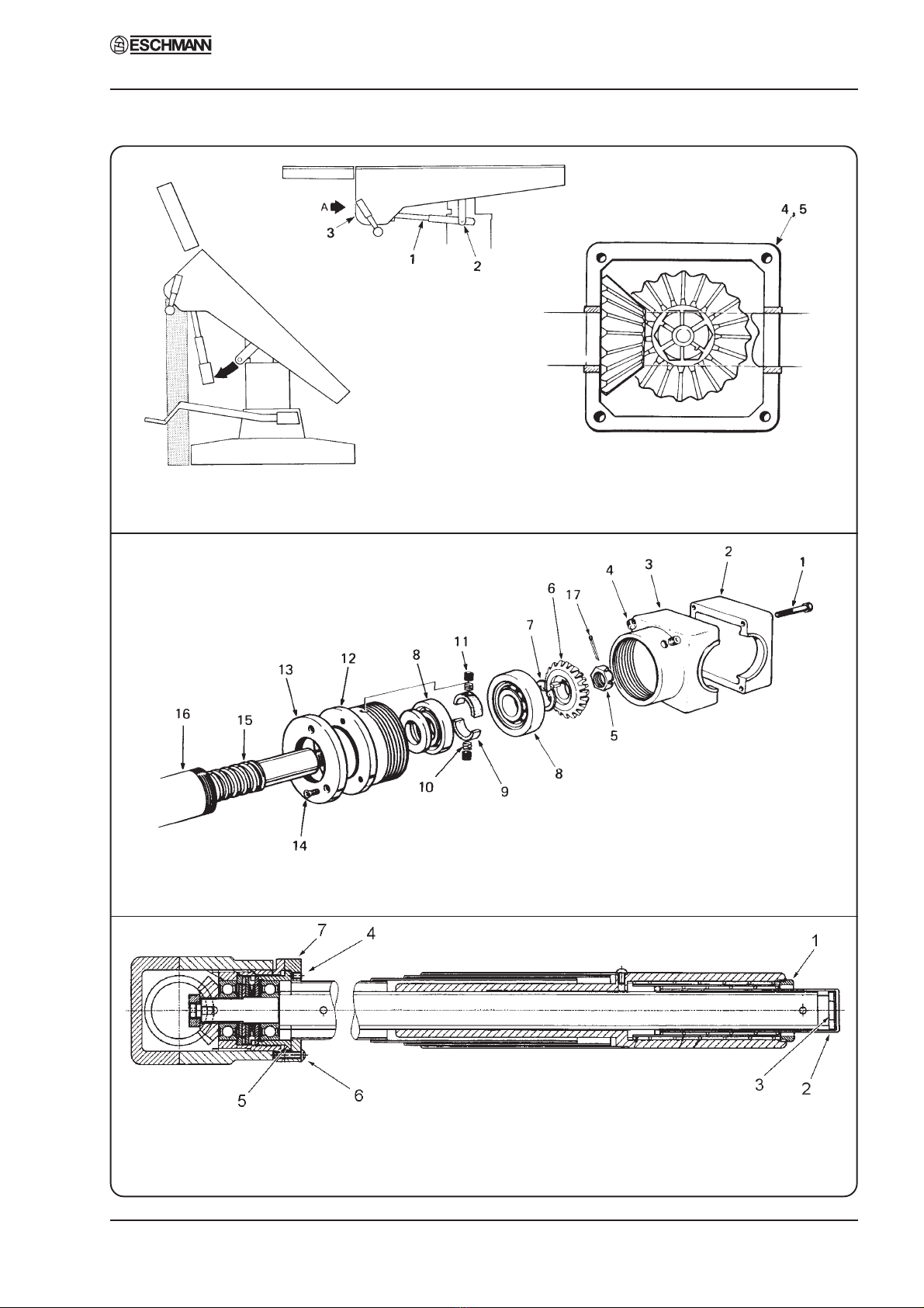
Fig. 4 Ram key adjustment
4.8 Raise the table top to its maximum height
again and release the ram cover securing screws
at the top. Refer to Fig. 4 and lower the 3-section
telescopic cover (1) to expose the ram (2) and ram
key (3).
4.9 Remove the ram key, clean out keyway and
refit key.
4.10 Examineram surface for rust and, if present,
clean off with fine emery cloth. (Note: Later rams
have a black surface coating do not confuse this
with rust and attempt to remove it). Lubricate
exposedsurfaceof ram. Sealthetop of thecylinder
withclothwound round theramto prevent damage
if using emery cloth.
T-SM5f Page 9 of 29
MR & MRS OPERATION TABLES Part 4
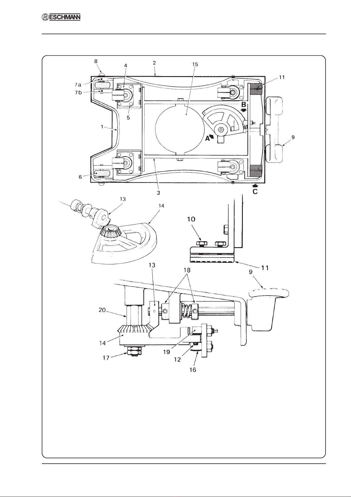
Fig. 5 Base assembly
1. Base casting 8. Wheel spindle 15. Oil sump
2. Base cover 9. Base control pedal 16. Roller
3. Castor frame 10. Brake pad screws 17. Quadrant securing nuts
4. Castor 11. Brake pad 18. Brake shaft collars
5. Castor mounting screw12. Stop screw 19. Eccentric pin
6. Wheel 13. Pinion 20. Quadrant pillar
7a/b. Grub screws 14. Quadrant
DETAIL A
DETAIL C
DETAIL B
4. MAINTENANCE
MR & MRS OPERATION TABLES
Page 10 of 29 T-SM5f
Part 4
4.11 Before refitting ram cover, check that table
will raise and lower smoothly. If this is not the
case, the ram key is probably secured too tightly.
Release the key attachment bolts (4) slightly to
remove excessive friction, then retighten.
4.12 Check for signs of oil leaks. If table will
not pump to its full height, refill reservoir with
the Eschmann oil supplied with the table, in small
measures, lowering the table after each addition.
This will avoid the risk of introducing too much
oil into the hydraulic system.
4. MAINTENANCE
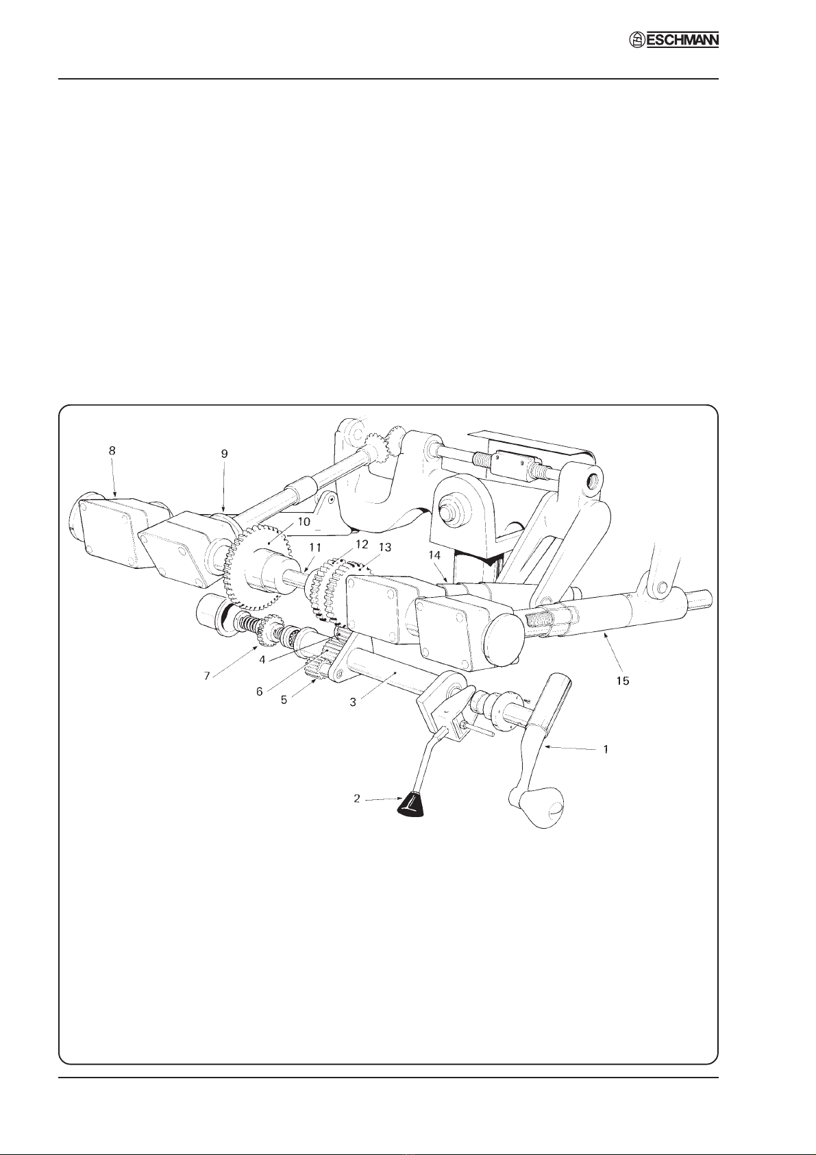
1. Main control handle 9. Pivot gear, lateral tilt
2. Gear selector lever 10. Drive gear, lateral tilt
3. Selector shaft 11. Gear shaft
4. Trendelenburg idler gear 12. Drive gear, break
5. Break idler gear 13. Drive gear, Trendelenburg
6. Gear selector unit 14. Trendelenburg screw and gearbox
7. Selector gear, lateral tilt 15. Break screw and gearbox (right hand)
8. Break screw and gearbox (left hand)
Fig. 6 Gearbox of MR operation table
Gears
4.13 Check function of gear selector lever in
conjunction with main control handle and ensure
that each table top movement is satisfactorily
achieved. Check to see if there is any excessive
play in table top in any particular direction (see
section 4.14 and 4.15). This applies particularly
to the two grub screws (4, Fig. 10) securing
screwed bush to screw housing on Trendelenburg
andBreak screw assemblies. Check friction collar
adjustment on Trendelenburg and Break screw
gears (see sections 4.16-4.19); also check that

T-SM5f Page 11 of 29
MR & MRS OPERATION TABLES Part 4
4. MAINTENANCE
gearson the idler plate (Fig. 6) still have clearance
and that securing screws are tight on driving and
idler gears in main gear train. Check grub screw
securing pivot bolt.
Hinge pin and nut
4.14 Pull table top as shown in Fig. 7 to check
for excessive play in the direction of the arrows.
If there is excessive play present refer to Fig. 7
and check to see if hinge nut (1) and bolt (2) are
loose. If so, * tighten hinge nut (1) against hinge
bolt (2) sufficiently to take up the slackness. To
do this, Eschmann recommend using two short
lengths of 3/16 in. diameter round bar (3) inserted
in the nut sockets, as illustrated in Fig. 7 and
applying an improvised tommy bar (4) to turn the
nut.
*Note: This could also indicate play in
Trendelenburggear.If this is the casethe complete
Trendelenburg screw assembly must be replaced.
For adjustment, see sections 4.16-4.18.
Sectional view in direction ‘A’
Fig. 7 Hinge pin and nut adjustment
Lateral screw and nut
4.15 Place table top in reverse Trendelenburg
position, then select Lateral Tilt and operate
control handle to test movement is satisfactory.
Pull as shown in Fig. 8. If undue play is suspected
refer to Fig.8 and proceed as follows:
i Check secureness of link pivot set screws
(6) and (7).
ii Checksecurenessofgrubscrewonyoke(5)
which locks lateral screw bearing.
CAUTION: Do not over-tighten.
Detail ‘A’ Detail ‘B’
Fig 8 Lateral screw and nut adjustment
iii Finger testing at the point where the lateral
screw (1) passes through the nut (2) will
establish the need for the nut adjustment.
First try tightening socket head screws (3)
on nut. If excessive play is still present,
shim removal will be necessary. Proceed as
follows:
(a) Unfasten socket head screws (3) on nut
and extract shim pack (4).
(b) Remove shims (0.002 in thickness per
shim, approx.) one at a time until play
is just taken up on re-tightening.

MR & MRS OPERATION TABLES
Page 12 of 29 T-SM5f
Part 4
Trendelenburg screw assembly friction
collars
NOTE: Sections 4.16 and 4.17 should only be
referred to for tables with serial numbers
preceding those detailed below, for later tables or
tables that have had the latest Trendelenburg
screws fitted refer to section 4.18.
Tables with serial numbers as detailed below have
the latest Trendelenburg screw fitted and section
4.18 applies :-
MR - 2060 (or above)
MRS - 1177 (or above)
4.16 Adjustment of the friction collars on the
TrendelenburgscrewMUST be checked regularly.
If the table does not easily stay in Trendelenburg
or reverse Trendelenburg position, but tends to
slip down under patient’s weight, this indicates
that the Tufnol friction collars (9, Fig. 10) need
tightening. Proceed as follows:
i Remove the leg section as described in the
InstructionManualandthenpumpthetable
top to maximum height with the height
adjustment pedal.
ii Elevate the head section to the maximum
raisedangleandplacethetableinmaximum
reverse Trendelenburg position.
iii Remove the gearbox cover (3, Fig. 9).
iv Bolster the tabletop in position as shown in
Fig. 9 and then free the lower end of the
Trendelenburg screw assembly (1, Fig. 9)
by removing the pivot screws (2, Fig. 9).
v Pivot the Trendelenburg screw assembly
about its bevel gear housing (4, Fig. 9) to
gain access, in turn, to the four screws
(5, Fig. 9) holding the two halves of the
housing together. Remove the four screws
toseparatethetwohalfhousingsandremove
theTrendelenburgscrewassembly,withthe
bevel gear lower half housing from the
table.
vi RefertoFig.10a.Markthebevelgearlower
half housing (3) and screwed bush (12) to
aid reassembly, then remove socket head
grub screws (4) from the half housing and
unscrew the screwed bush (12) until heads
4. MAINTENANCE
of friction collar grub screws (11) are
exposed.
vii Tighten grub screws (11), securing friction
collars (9), to a torque of 16 to 17 lbf in.
viii Screw screwed bush (12) into the half
housing and secure with socket head grub
screws (4).
ix Usingasuitabletorquewrench(e.g. Torque
driver-Part No. 759581 and 4mm Bit-Part
No. 759582), attached to nut (17) using
adaptor (Part No. 759566), check final
friction of screw shaft (15); the torque
required to turn screw shaft (15) should be
between 30 and 35 lbf in. If final friction
torque cannot be achieved, further tighten
each friction collar grub screw (11), by 1 to
2 lbf in. per occasion until 30 to 35 lbf in.
torque is achieved. If torque figure is not
achievedbyamaximumsetting of 20lbfin.
then refer to section 4.17.
4.17 If further friction cannot be obtained by
carrying out the above procedure, the friction
collars are worn and a new Trendelenburg screw
assembly should be fitted. Refer to section 4.34
under REMOVAL AND INSTALLATION OF
COMPONENTS.
4.18 For tables having the latest design of
Trendelenburg screw assembly (see note
preceding 4.16) the adjustment of the friction
collar on the Trendelenburg screw MUST be
checked regularly. If the table does not easily stay
in Trendelenburg or reverse Trendelenburg
position, but tends to slip down under patient’s
weight, this indicates that the friction collar needs
adjusting. Refer to Fig. 10b and proceed as
follows:
i Remove the leg flap and place gear lever in
Lateral Tilt position.
ii Unscrew sleeve cap (1) and remove the end
captubes(2)fromtheTrendelenburgscrew
assembly.
iii Using torque screwdriver (Part No. 759581
set to 20-25 lbf.in. and fitted with adaptor
T2095 Part No. 759653 and 20mm socket),
checkthesettingbylocatingsocketoverthe
T-SM5f Page 13 of 29
MR & MRS OPERATION TABLES Part 4
4. MAINTENANCE
View on Trendelenburg screw bevel
gear - half cover removed.
Fig. 9 Releasing Trendelenburg screw assembly
Fig. 10b Later* Trendelenburg screw assembly
(* To determine which Trendelenburg screw is
fittedtoatable,seenoteprecedingsection4.16)
Fig. 10a Early* Trendelenburg screw assembly
(* To determine which Trendelenburg screw is
fitted to a table, see note preceding section 4.16)

MR & MRS OPERATION TABLES
Page 14 of 29 T-SM5f
Part 4
hexagon(3)ontheendoftheleadscrewand
turning the torque screwdriver.
iv If the leadscrew rotates before the torque
screwdriverreaches20-25lbf.in.thefriction
collarrequires adjusting as (v) below.If the
leadscrew does not rotate the friction collar
setting is correct and requires no further
adjustmentandthetablecanbereassembled.
v Adjust the friction collar by slackening the
single grub screw (4) that locks the torque
adjuster nut (5) and removing the three
screws (6) securing the cap ring (7) located
at the rear of the gearbox housing thus
exposingthetorqueadjustingnut(5).Locate
spanner (tool number T2097 Part No.
759652)ontothetorqueadjusternut(5)and
tightenorslackento gain the correctsetting
(i.e.the torque setting is between that given
in (iii) above but operation of the
Trendelenburg handle is not too difficult).
vi Replacethecapring(7)andsecureusingthe
threescrews(6),lockthetorqueadjusternut
(5) by tightening the single grub screw (4)
and reassemble the table.
Chair and Break screw assembly friction
collars
4.19 Should the ‘Chair and Break’ screw friction
collars ever require adjustment, the procedure is
similar to that for the Trendelenburg screw
assembly (see 4.16 to 4.18), once the ‘Chair and
Break’ screw assembly has been released from
the gear shaft. (Note that MR tables with serial
number 2099 or below have the earlier design of
screw detailed in sections 4.16 to 4.18 and tables
above2099 have the latest design screw. All MRS
tables have the early design ‘Chair and Break’
screw).
Control arm (cable type) - MRS only
4.20 The control arm of early tables were cable
operated and were fitted to tables with Serial
Number 1023 or earlier. Refer to Fig. 11 and
remove the control arm cover, then:
i Check chain links (1)
ii Check gears and keys (2)
iii Ensure lubrication of cable (3)
iv Check cable bends and cable nipples (4)
(also see Fig. 15).
Control arm (gas spring type) - MRS only
WARNING
Gas springs are filled with
high pressure gas.
DO NOT ATTEMPT TO OPEN THEM
CAUTION
Gas springs MUST NOT be
additionally lubricated.
4.21 Gas spring operated control arms have been
fittedto tablesfrom Serial Number 1024 onwards.
Remove the extended head end control arm cover
(see Fig. 20) and carry out the following
procedures to ensure the correct function of the
control arm.
i Check gears and keys and that the chain
operates smoothly and is not loose. If the
chainislooseitcanbeadjustedbyreleasing
the three screws located around the main
controlhandle mounting plate. This plate is
eccentric and rotating it will alter the chain
tension and remove slack, lock the main
4. MAINTENANCE
Fig. 11 Control arm (early MRS table)

T-SM5f Page 15 of 29
MR & MRS OPERATION TABLES Part 4
4. MAINTENANCE
Fig. 12 Removing hydraulic cylinder from table base
(A) (B)
(D)
(C)

MR & MRS OPERATION TABLES
Page 16 of 29 T-SM5f
Fig. 13 Hydraulic cylinder assembly
Part 4
control handle in position with the three
screws when adjustment is correct.
ii Check the operation of the gas spring and
look for any signs of leakage. Replace the
gasspring(see section4.59)ifperformance
is poor or there are signs of leakage. (Note
the Warnings and Cautions regarding gas
springs between sections 4.20 and 4.21).
iii Lubricateallmovingpartsusingpartnumber
670010.
iv Oncompletionof routinechecksoncontrol
arm replace cover and check all functions.
Emergency operation - early MRS table only
4.22 This section only refers to tables with cable
operated control arms (i.e. pre Serial Number
1025). Refer to the latest version of the
Instructions for Use, Publication No. T-IM18 and
placethetable in emergency operation. Checkthat,
with the emergency gear lever in the three
alternative positions, the table top will move in
the corresponding directions by use of the main
control handle.
Head/leg section and catches
4.23 Proceed as follows for old style sections
without gas spring supports, for sections with gas
springs refer to section 4.24.
Note: Gas spring supports were not fitted to head
sections of tables pre Serial Number 1026 for
MRS and pre Serial Number 676 for MR, or leg
sections of tables pre Serial Number 1017 for
MRS and pre Serial Number 315 for MR. Tables
withthese Serial Numbers or later have gas spring
supports.
i Clean out any collected debris from the
recesses of the locking and guide pin push
button catches (4, Fig. 17) in the trunk
sectionsofthetable.Refertosection4.49to
4.52 and dismantle each push button check
each component for damage or wear
replacingasnecessary,Checkspring-loaded
nylonplungers(2,Fig.17)forsmoothaction.
Clean and lubricate the catch mechanism
then reassemble (again referring to section
4.49 to 4.52.) and test.
ii Lubricate rack and fine adjustment
movement of head/leg section.
4. MAINTENANCE

T-SM5f Page 17 of 29
MR & MRS OPERATION TABLES Part 4
4. MAINTENANCE
iii Check tightness of pivot screws and grub
screws on head and leg sections.
iv Check tightness of socket headed pivot
screws (5, Fig. 18) and cap nuts (4, Fig. 18)
onquickreleasebar(3,Fig.18)onheadand
leg sections.
v Check secureness of grub screw on fine
adjustment handwheel (1, Fig. 18) on head
section only (also see section 4.53).
vi Check clean and lubricate locking pin
(7, Fig. 18)andguidepin(8,Fig.18) with a
light machine oil on head and leg sections.
4.24 For tables with head and leg sections
incorporating gas spring supports (see note in
section4.23above for theSerial Numbers of tables
that do) refer to Fig. 19 and proceed as follows
noting WARNINGS and CAUTIONS preceding
section 4.21:
i Check,cleanandlubricateguidepincatches
as 4.23(i) above.
ii Check clean and lubricate locking pin (23)
and guide pin (25) with a light machine oil
on head and leg sections
iii Testtheactionofthe releasehandleandgas
spring. If the gas spring support is
unsatisfactory (head or leg section fails to
maintainitsposition)thecompletegasspring
unitmustbereplaced,theycannotbeserviced
(see section 4.58). Also seepage of fluid
indicatesafailingunitthatmustbereplaced.
iv Examinetheradiographictoppanelforsigns
of any damage (e.g. cracks or chips) and
check that the securing spring collars of the
radiographic top are not damaged.
FAULT DIAGNOSIS AND REMEDIES
Excessive rotational movement of table top
4.25 Rotational movement of the table top is
controlled by the tapered ram key (3, Fig. 4).
Excessive movement is due to wear of the ram
key increasing the clearance in the keyway. This
canbe corrected by slightly loosening the ram key
clamping bolts (4, Fig. 4), gently tapping the key
into the keyway until excess movement has been
removed and retightening the clamping bolts.
Check that the ram key has not been over-
tightened by fully raising and lowering the table
top.Ifthe table topwill not raise orlower correctly,
the ram key has been over-tightened and must be
slackened until normal raising and lowering of
the table top can be achieved.
Inability to raise table top
4.26 If normal operation of the height control
pedal fails to raise the table with the pedal
Fig. 14 Ram release mechanism - adjustment

MR & MRS OPERATION TABLES
Page 18 of 29 T-SM5f
Part 4
travelling through its full stroke, the fault is
probably due to the presence of dirt in the ball
valve, (1, Fig. 13) of the hydraulic cylinder. It is
often possible to clear this obstruction by
vigorously operating the height control pedal. If
this fails, remove hydraulic cylinder from base
(see section 4.35); the ball valve should then be
disassembled and cleaned (see section 4.37). If
the pedal is suddenly inoperable either when
raising or lowering the table, refer to section 4.28.
Table top not maintaining height
4.27 If table top fails to maintain height, raise it
to its maximum height, fully depress the height
control pedal and, by pressing on the table top,
force the table top downwards as quickly as
possible. Repeat this operation several times. If
this does not rectify the fault remove hydraulic
cylinderfrom base (seesection 4.35) thenexamine
the hydraulic mechanism for:
i Condition of ball valve jointing washer (2,
Fig.13).Iffaulty,replaceit(seesection4.37).
ii Securenessoframcoverplate(3,Fig.13).If
it is loose, retighten it.
iii Efficiency of ball valve (1, Fig. 13). If
blocked or jammed, disassemble and clean
it, (see section 4.37). If the seating of the
larger (spring-loaded) ball has been
damaged, replace the complete valve.
iv Condition of ram cup washer (4, Fig. 13). If
wornorchipped,replaceit(seesection4.36).
Operation table will not lower
4.28 Firstexamine thesteel ram for rust (see note
below); a type of black rust not easily noticed can
form on the circumference of the ram. This can
be identified by rubbing a piece of emery paper
on any discoloured portion of the ram surface. If
rust is detected, it must be removed completely,
as follows:
NOTE: Later tables have a black coating which
prevents this rust occurring.
i Protect the top of the cylinder by tying a
piece of rag around the ram.
ii Cleantheramsurfacethoroughlybyrubbing
hard with emery paper.
4. MAINTENANCE
iii Carefully clean off all particles of grit and
completely cover the exposed ram surface
with oil.
iv Test the raising and lowering movement of
the table top.
4.29 If on testing the table pump mechanism for
normal function it is found to be still inoperable
this may be due to the fact that efforts made to
lower the table while seized have strained the
pump lever driving pin or the ram release
mechanism. If the table top descends at all in
responseto pump lever operation, thedescent will
be sluggish. To remedy this the following
procedure should be carried out:
i Refer to section 4.35 and remove hydraulic
cylinder from table base.
ii Examination of the ram release movement
must now be carried out. Refer to Fig. 14.
Whenthepumpleverisdepressedfully,this
operates the ram release lever (1). The ram
releaseleverpivotsandthereleasescrew(2)
enters the ball valve and should lift both
balls (3 and 6) at the end of lever travel.
Before testing this movement, the pressure
in the ball valve should be overcome by
forcing the release lever into the ball valve
after covering the cylinder with a cloth to
avoid leakage of oil under pressure.
iii Now depress the pump lever fully and hold
inthisposition.Testtheramreleaseleverby
tryingthe movement using thumb pressure.
If the movement is other than very slight,
adjustment is required.
4.30 To adjust ram release mechanism, proceed
as follows:
i Position the compression tool clamp
(includedinthetoolkitavailablefortheMR
series tables, Part No. 751030) across the
baseofthecylinder(seeFig.12c)andlightly
tightenitontotheramrelease.UseanAllen
key to remove the four screws holding the
ram release in position.
ii Loosentheclampuntiloilstartstorunfrom
the hole. Allow the oil to drain.
iii Continue to unscrew the clamp until
T-SM5f Page 19 of 29
MR & MRS OPERATION TABLES Part 4
4. MAINTENANCE
completely loose then remove clamp and
ram release (see Fig. 12(d)).
iv Refer again to Fig. 14. Adjustment consists
ofunscrewing,in a clockwisedirection, the
two large lock nuts (4) on the end of the
releaseplunger(5)toallowmoremovement
of the ram release lever. This is in order to
cause the ball of the ball valve to be lifted
further and so release the table ram. (For a
more detailed explanation of the hydraulic
system, refer to section 4.60 and 4.61).
Note:This adjustment can only be made on a trial
and error basis. Each time an adjustment is
made the ram release must be refitted into
the cylinder and the pump lever tried and
held to ascertain whether the release screw
on the lever projects too far into the ball
valve, or still not enough. Care must be
taken to adjust this correctly as strain will
occur either side of the normal. As a guide,
thenormalsettingis1/16inbetweenrelease
screwandballvalvehousing(approximately
the thickness of an engineer’s steel ruler).
v Whenthecorrectadjustmenthasbeenmade,
lift the cylinder and table top bodily and
guide the cylinder back into the well of the
base.DONOT ALLOW THECYLINDER
TO DROP INTO THE BASE. When the
table is in an upright position and before
lowering it into the base, refit the locking
lever. This will prevent the escape of oil
fromthecylinder. Thetabletopshouldnow
raise and lower normally.
Note:Ifitisfoundthatthedrivingpinofthepump
pedal has been bent - too badly for any
adjustment - a new pump lever must be
fitted.
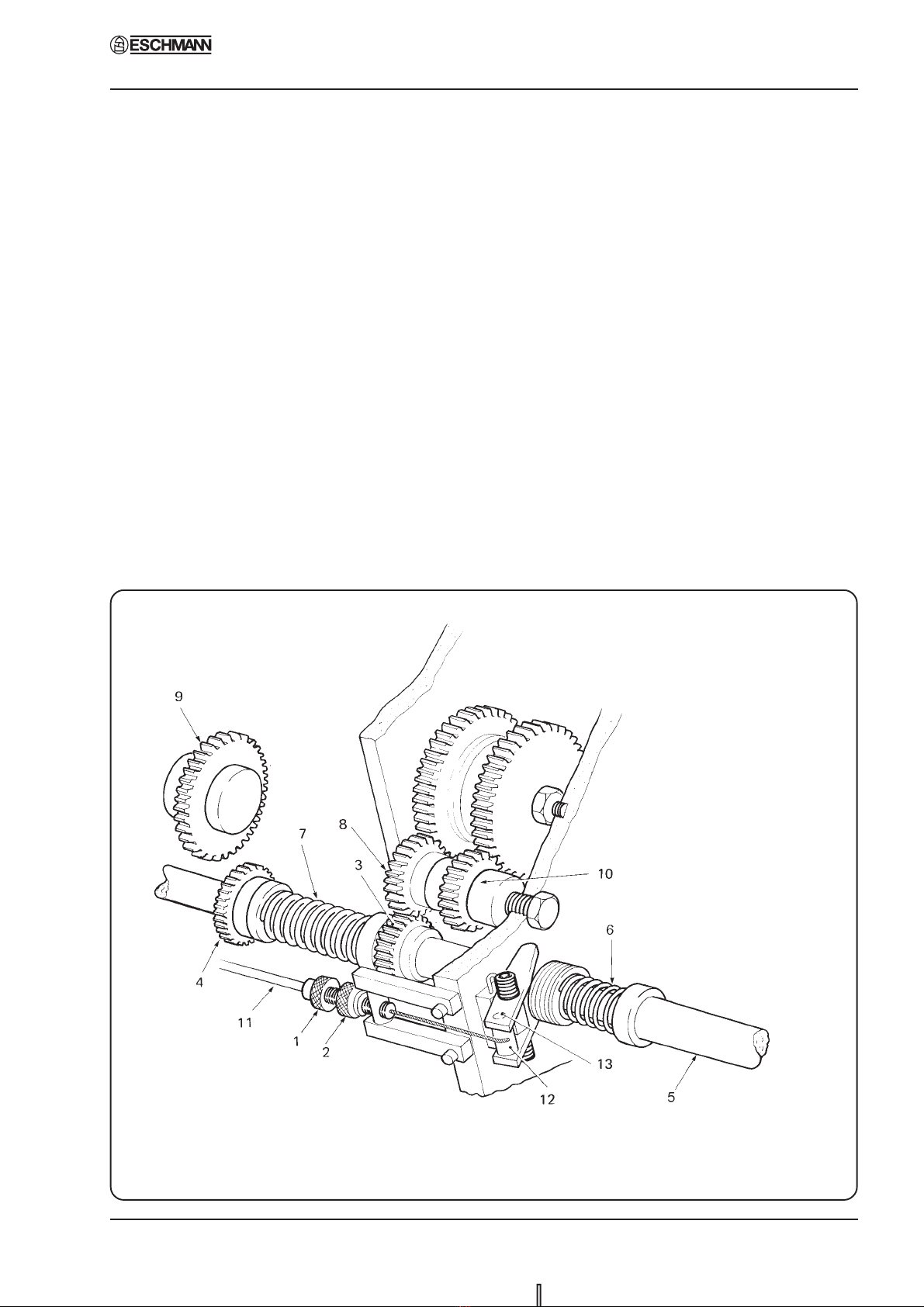
Fig. 15 Control arm cable adjustment/replacement - MRS table pre Serial No. 1024

MR & MRS OPERATION TABLES
Page 20 of 29 T-SM5f
Part 4
Failure of cable operated control arm gear
selection, MRS table only (pre Serial No.1024)
4.31. Thecontrol arm gearlever operates the table
topmovementselection mechanism inthe gearbox
by means of a flexible cable assembly (3, Fig. 11).
If movement selection fails to function correctly
while the table is in use, immediate action must
be taken to engage the standby controls. The fault
symptoms can be any of the following:
i Thegearselectorlevermayhavebeenstruck
andbent,causinggearselection tobeupset.
ii Trendelenburg movement is permanently
engagedbutthegearleverdoesnotspringto
this position when placed in the vertical
gate. This indicates that the ferrule at either
end of the inner cable has been sheared-off,
in which case the cable assembly should be
renewed or the ferrule resoldered to the
inner cable (see section 4.40).
iii Lateral tilt or flexion/extension movement
isnotengagedwhenthegearleverismoved
into the appropriate position.
iv Trendelenburg and flexion/extension
movements are engaged simultaneously
when the gear lever is in either of these two
positions.
4.32. Symptoms (iii) and (iv) indicate that the
inner cable has stretched and the mechanism
should be adjusted as follows:
i Select Trendelenburg movement.
ii Refer to Fig. 15 and locate adjusting screw
(1) beneath upper trunk section.
iii Slacken thumb nut (2).
iv Check that selector gears (3) and (4) slide
freely on the main shaft (5) and that the
returnsprings(6)and(7)functioncorrectly.
v Check that the selector gear (3) is in full
mesh with the idler gear (8); if necessary
turn the adjusting screw (1) in the direction
required to achieve this condition.
vi Select lateral tilt movement.
vii Check that the selector gear (4) is in mesh
with the drive gear (9) and that the selector
gear(3)iscompletelydisengagedfromboth
idler gears (8) and (10). Small adjustments
to the adjusting screw may be made to
achieve these conditions.
viii Select chair and break movement.
ix Check that the selector gear (3) is in mesh
with the idler gear (10) and that the selector
gear (4) is disengaged from the drive gear
(9).
x Repeatthechecks(5)to(9)withthe control
arm in two or three different positions,
making small adjustments to the adjusting
screwif necessary to establish the optimum
setting.
xi Tighten the thumb nut.
Control arm not maintaining position (MRS
table with gas spring, Serial No. 1024 or later)
4.33 If the control arm will not maintain its
position this is normally indicative of a faulty gas
spring. Remove the lower control arm cover (as
shown in Fig. 20) and check for signs of a
damaged or a leaking gas spring, replace if
required, see section 4.58. Do not lubricate gas
springs and do not attempt to repair them (see
WARNINGS and CAUTIONS above section
4.21).
REMOVAL AND INSTALLATION OF
COMPONENTS
Replacement of Trendelenburg screw (Fig. 9
and 10)
4.34 Toreplacethe Trendelenburgscrew, remove
the old Trendelenburg screw assembly from the
operation table as detailed in 4.16. Fit a new
Trendelenburg screw assembly (latest style see
note above 4.16) and adjust it to the correct torque
setting as detailed in section 4.18. Reassemble the
table.
Note: The bevel gear housing has one thick and
onethinside wall.Thethinsidewallshould
be fitted round the neck of the gear shaft
bevelgear.Ensurethattheupperbevelgear
housing is orientated to match before
attempting to refit the cap head screws
securing the two halves of the housing
together.
4. MAINTENANCE
This manual suits for next models
1
Table of contents
Other eschmann Medical Equipment manuals


