eschmann RX600 User manual
RX600
OPERATION TABLE
606049
Service Manual
T-SM14g

Service Manual
Preliminary Information
Technical Data
Safety Notes
Introduction
Description
Maintenance
Eschmann After Sales Service Department
TheEschmannAfter SalesServiceDepartmentisstaffedandequippedtoprovideadviceand assistance
during normal office hours.To avoid delays when making enquires, please quote the Model and Serial
Number of your Operation Table which is shown on the Serial Number plate, the location of which is
shown below.Please ensure you include all alpha and numeric digits of the Serial Number.
For further information visit www.eschmann.co.uk
All correspondence relating to the after sales service of Eschmann Equipment to be addressed to :
UK Customers
Eschmann Equipment,Peter Road, Lancing,West Sussex , BN15 8TJ, England.
Tel: +44 (0) 1903 765040. Fax:+44 (0) 1903 762006.
Overseas Customers
Contact your local distributor. In case of doubt contact Eschmann Equipment.
Patents andTrade marks
The ESCHMANN name and logo are registered trade marks of Eschmann Holdings Limited.
“Eschmann Equipment”is a trading name of Eschmann Holdings Limited.
“RX600” is a trade mark of Eschmann Holdings Limited.
Patents: GB 2260075 & GB 2242624;France 536922 & 450836;US5116032;
Germany P69206378.1 & P69104883.5;Italy 536922 & 450836.
Patents pending in Japan, application numbers 263630/92 & 97990/91.
Copyright © 2002
Allrightsreserved.Thisbooklet isprotectedbycopyright.No part ofit maybe reproduced, storedina retrieval
systemortransmittedinanyformorbyany means,electronic,mechanical,photocopying,recordingorotherwise
withoutwritten permission from EschmannHoldingsLimited.
Theinformationinthispublicationwascorrectatthetimeofgoingtoprint.TheCompany,however,reservesthe
right to modify or improve the equipment referred to.
If the CE mark is affixed to the product, it indicates compliance with Council Directive
93/42/EEC of 14 June 1993 concerning medical devices.
T-SM14g October 2002
The Serial Number plate can
be found on the inside of the
long trunk section casting
indicated here.

T-SM14g 3/44
RX600RX600
RX600RX600
RX600
OPERATION TABLE
READ THESE INSTRUCTIONS BEFORE USE
Keep these Instructions in a safe convenient place for future reference. Read in conjunction
with the relevant Publications detailed in the preliminary information section.
CONTENTS
Section Contents Page
1. PRELIMINARYINFORMATION.............................. 4
2. TECHNICALDATA ................................................. 4
3. SAFETY NOTES ................................................... 5
4. INTRODUCTION .................................................... 6
General .............................................................. 7
Electrical system ............................................... 7
Maincontrol board ......................................... 7
Heightopto board........................................... 7
Basedistribution board .................................. 8
Top-of-columndistributionboard..................... 8
Top-of-columnsolenoids board....................... 8
Tiltoptoboard................................................ 8
Power circuits ................................................ 8
Handcontrol .................................................. 8
Footswitch ..................................................... 8
Table-baseon/off control ................................ 9
Built-inbattery charger ................................... 9
Externalbattery charger................................. 9
Standby system connections......................... 9
Tractionbeam stowagedetection ................... 9
5. DESCRIPTION .................................................... 10
6. MAINTENANCE................................................... 14
General ............................................................ 14
Cleaningand storage ....................................... 14
Generalcare andlubrication............................. 14
Gassprings ................................................. 14
Head, hip & leg sections & sacral extension 14
Headandhip locking mechanisms............... 14
Long and short trunk sections...................... 14
Radiographictops ........................................ 15
Undersideofthe table base ......................... 15
Tractionbeam attachment............................ 15
Access to fuses........................................... 18
Handcontrol ................................................ 18
Aftermaintenance........................................ 18
Functional checks............................................ 18
General ........................................................ 18
Hydraulic system ............................................. 19
General ........................................................ 19
Topping-up hydraulic reservoir ...................... 19
Adjustments .................................................... 19
Trendelenburgmicroswitch ........................... 19
Lateral tilt opto ............................................. 19
Breakmicroswitch ....................................... 19
Level tilt switch............................................ 20
Traction beam swivel joints .......................... 22
Removaland installation .................................. 22
General ........................................................ 22
Removetablebase covers .......................... 22
Install table base covers .............................. 22
Removetop-of-column covers ..................... 23
Installtop-of-columncovers......................... 23
Releasingtelescopiccover andupstand ...... 23
Replacingtelescopiccover andupstand ...... 23
Removing telescopic cover .......................... 23
Replacingtelescopiccover .......................... 23
Remove long and short trunk assembly....... 23
Install long and short trunk assembly .......... 24
Section Contents Page
Removebreak cylinder ................................ 26
Install break cylinder.................................... 26
Remove lateral tilt cylinder........................... 29
Install lateral tilt cylinder.. ............................ 29
RemoveTrendelenburgcylinder.................... 28
InstallTrendelenburgcylinder ....................... 30
Removeheight cylinder................................ 30
Install height cylinder ................................... 30
Gasspring replacement ............................... 31
Removebatteries......................................... 31
Install batteries ............................................ 31
Remove the base feet.................................. 31
Install the base feet ..................................... 32
Infillinterlockingmechanism replacement.... 32
Pushbuttonreplacement andadjustment .... 32
Tractionbeam removal ................................. 33
Tractionbeam replacement .......................... 33
Remove swivel joint from short trunk ........... 33
Refit swivel joint to short trunk..................... 33
Traction beam swivel joint ............................ 33
Hydrauliccomponent replacement ............... 34
Electricalcomponent replacement ............... 34
Fault diagnosis................................................. 34
Circuitdiagram index ....................................... 37
Table 1 - Fault diagnosis............................................ 35
Table 2 - Codes for 2-digit display.............................. 38
Fig.1 RX600PoweredOperationTable ........................ 6
Fig.2 RX600Operationtable -basedetail ................. 10
Fig.3 RX600Operationtable -column/trunkdetail .... 12
Fig.4 RX600basedetail (longtrunkend) .................. 13
Fig.5 RX600basedetail (short trunk end) ................. 13
Fig.6 Table tilted for access to underside .................. 14
Fig.7 Undersideof table base ................................... 15
Fig.8 Adjustment of beam attachment ...................... 15
Fig.9 Hydraulic system - Schematic diagram............ 16
Fig.10Hydraulic system - main components .............. 17
Fig.11Maincontrolboard ........................................... 18
Fig.12Trendelenburgmicroswitch ............................... 18
Fig.13Lateral tilt opto detail........................................ 18
Fig.14Break microswitch ........................................... 20
Fig.15Level tilt switch ................................................ 20
Fig.16Swivel joint detail ............................................. 21
Fig.17Cover retainingpush rivets .............................. 23
Fig.18TopofTrendelenburgcylinder ........................... 24
Fig.19Top-of-column hingeassemblydetail ............... 25
Fig.20Break cylinders ................................................ 27
Fig.21Lateral tilt cylinder............................................ 28
Fig.22Trendelenburgcylinder ..................................... 29
Fig.23Top-of-columndetail ......................................... 30
Fig.24Bottom of height cylinder detail........................ 30
Fig.25Gas springdetail.............................................. 31
Fig.26Base feet detail................................................ 31
Fig.27Infill interlocking mechanism ............................ 32
Fig.28Catch mechanism ............................................ 32
Fig.29Beamattachment ............................................ 33
Fig.30Swivel joint attachment detail .......................... 33
Fig.31Handcontrolfunctions ..................................... 38
Fig.32-40Circuit diagrams (seeIndex page 37)......39-42
4/44 T-SM14g
1. PRELIMINARY INFORMATION
1.1 This Service Manual should be referred to for details of the RX600 Powered Operation Tables,
REF 80-606-59 and REF 80-606-13, Serial Number R6AC9K1001 or above.
RelatedTechnical Publications available on request :-
Instructions for Use -T-IM33 (issue ‘d’or later) - RX600 Powered Operation Table
Illustrated Parts List - T-IPL13 (issue‘b’or later) - RX600 Powered OperationTable
1.2 Instruction and Service Manuals should be readily accessible for reference prior to and when operating, cleaning
andservicingtheOperationTable.Allmanuals areavailablefromEschmann Equipment,seeinside front coverfor address
details. 2.TECHNICAL DATA
DIMENSIONS
Table with standard table-top (Fig. 1):
Width including sidebars .............................560mm
Sidebars ......................................(31.75 x 6.35)mm
Overall length (with infill section)...............1975mm
Minimum table height (without mattresses) .... 700mm
Maximum table height (without mattresses). 1040mm
MOVEMENTS
Maximum Trendelenburg....................................35°
Maximum Reverse Trendelenburg......................15°
Maximum Lateral Tilt (left and right)...................15°
Maximum Extension.........................................210°
Maximum Flexion .............................................130°
Head section adjustment ................................ ±45°
Note: With the table at minimum height, maximum
Trendelenburg, and maximum head and leg section
movements are reduced.
WEIGHT (nominal)
Table with standard table-top (Fig. 1) ............ 300kg
SAFETY
The table is built to comply with BS5724 Part 1,BS5724
Part 2 Section 2.22, IEC601-1 and BS6859 Part 1. The
mattresses comply with BS2891.
TABLE LOADING
The standard table (Fig. 1) satisfies a static load test in
accordance with the requirements of BS5724.
WARNING
The RX600 has been designed for patients up
to 135kg with their centre of gravity (normally
the perineum) over the infill or trunk sections.
Patient positioning and additional loads can
compromise table stability. The perineal
extension may be used to further offset the
patient, however,always ensure loading does
not compromise stability.
To comply with IEC601-1:1988 some access-
ories have been designed for a maximum
evenly distributed load. For the divided-leg
section this is 15kg per leg section (also see
PublicationT-IM49 issue ‘b’or later) and 10kg
for the detachable ophthalmic head-flap.
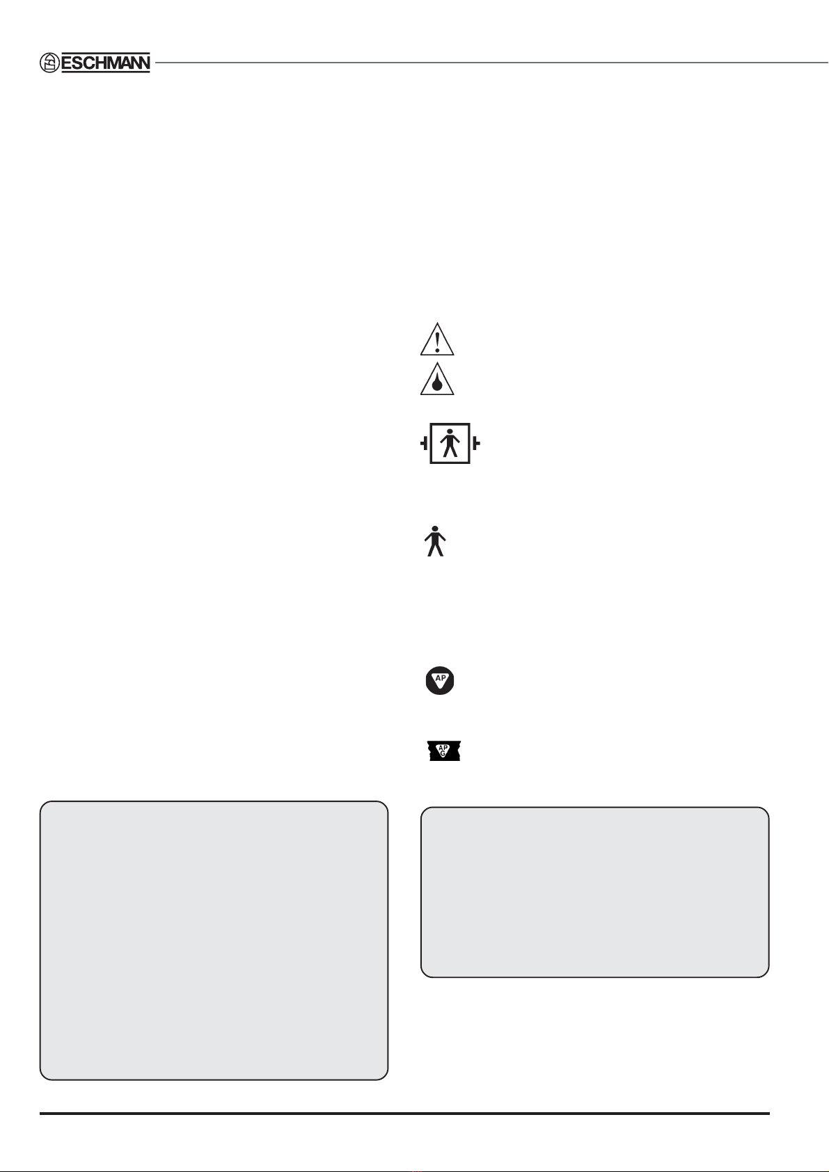
SYMBOLS & SAFETY CLASSIFICATIONS
Caution Refer to the accompanying documents,
the “Instructions for Use”.
or IPX 4 indicates that the equipment will withstand
a moderate quantity of fluid spilled from above.
Safety category
Indicates that the equipment is in safety category
BF,i.e.itismanufacturedtoasafetystandardwhich
agrees with international regulations for medical
electrical equipment,andprovidesahigh degreeofprotection
against electric shock. The symbol also indicates that the
equipment will not be damaged by defibrillator discharge.
Indicatesthat theequipmentisinsafetycategoryB, i.e.it
is manufactured to a safety standard which agrees with
international regulationsfor medical electrical equipment,and
providesaminimumdegreeofprotectionagainstelectricshock.
Class 2 Indicates that the built-in battery charger is
designed to electrical protection Class 2.
Anaesthetic proof
Indicates that the parts of the equipment marked
AParedesigned forusewithin adistanceof 5-25cm
of a part of an enclosed medical gas system. BS5724
Part 1, 1989 refers.
IndicatesthatthepartsoftheequipmentmarkedAPG
are designed for use within a distance of 5cm of a
partofanenclosedmedicalgassystem.BS5724Part1,1989
refers.
WARNING
The head section of this operation table is
classified as‘EQUIPMENT not suitable for use in
the presence of a flammable anaesthetic mixture
with air or with Oxygen or Nitrous Oxide’ and is
NOT classified as ‘Category AP Equipment’ or
‘Category APG Equipment’ when it (the head
section) is in its lowest position and the table top
is in fullTrendelenburg position.
Inspection
The table must be inspected at regular intervals, and if
necessary, serviced, to ensure that it complies with all AP
and APG requirements relevant to physical deterioration
or breakage of electrical components, connections and
cableinsulation.

T-SM14g 5/44
RX600RX600
RX600RX600
RX600
OPERATION TABLE
Antistatic requirements
The table has an antistatic pathway from the table-top,
through an internal resistor, to the castors, which are held
in contact with the floor at all times.
CAUTION
1. To complete the antistatic pathway, the
table must be used on an electrically
conductive, or on an antistatic floor.
2. Alwaysusepurpose-designedEschmann
mattresses to maintain the antistatic pathway.
Electrical data
System power
Batteries:
Type........................................Two sealed lead-acid
Output (each) ......................................... 12V 24Ah
Built-in battery charger:
Input ...................... 100-120 / 200-240Vac 50/60Hz
Output ..............................27.6Vdc (nom) 3A (max)
System fuses:
Motor.......................................30A 1.5in. (AGU 30)
Base Control Board: (1)........F6.3A 250V 20mm
(1)........T2.5A 250V 20mm
(1)...........T2A 250V 20mm
CAUTION
This equipment contains environmentally
hazardous lead-acid batteries. If the batteries
fail, or if the equipment is to be disposed of,it
is recommended that the batteries are taken
to a disposal site designated for the disposal
of lead-acid batteries, or that the batteries are
collected by an agent who specialises in the
collection of lead-acid batteries.
Hydraulic oil
Type.....................Eschmann RX (Part No.699408)
3. SAFETY NOTES
Attention to the following points will prolong the life and efficiency of the RX600 Powered
OperationTable and will help to avoid the risk of accidents, or damage.
DO:
?Keep the Instruction for Use close-to-hand.
?Read the instructions carefully before using table.
?Checkthattheheadandleg sectionsaresecure, and
put the table base in the braked position before use.
?Disconnect the built-in battery charger from the
power supply before washing the table.
?Read and follow the instructions for cleaning, and
for the care of the mattresses.
?Use the correct mattresses and accessories.
?Remove table accessories and their clamps (in
particular rotary clamps) from sidebars, when they
are not being used.
?Ensure that the table and accessories are serviced
at regular intervals (every 6 months is the
recommended frequency) by Eschmann personnel
only, or accredited agents.
?Store the table as detailed in this manual.
DO NOT:
?Lift the table by its table-top.
?Push the table over rough surfaces, use a trolley.
?Drop the table (or individual sections).
?Put heavy weights on the table sections.
?Put sharp objects on, or against, mattresses, pads,
or the radiographic table-tops.
?Dropheavyobjects ontotheradiographictable-tops.
?Spill oil, ether, or other fluids onto the mattresses
or the pads.
?Pull the table by any of the table-top sections,
always push it.
?Hold or support the leg section by its black
radiographic top, as this is a removable item and
might come off.
Note: The table cannot be used (under normal
circumstances) with table base stand-by door open.
WARNING
The RX600 Powered Operation Table has been designed to minimise the possibility of accidental
electrosurgery burns. Contact with any metal surfaces (e.g. table side bars, or other equipment
etc.) can cause burns during electrosurgery and must be avoided.
With the table in (or during transition into) the castor position, the centre of gravity of the patient
(normally the perineum) should lie no more than 200mm away from the centre of the column (i.e.no
more than the length of the short trunk section). Whenever this is not practical the overhanging
weight of the patient and table should be adequately supported (e.g. by at least two able people).
Also see Warnings in the Instruction for Use and within the text of this publication.
2. TECHNICAL DATA
6/44 T-SM14g
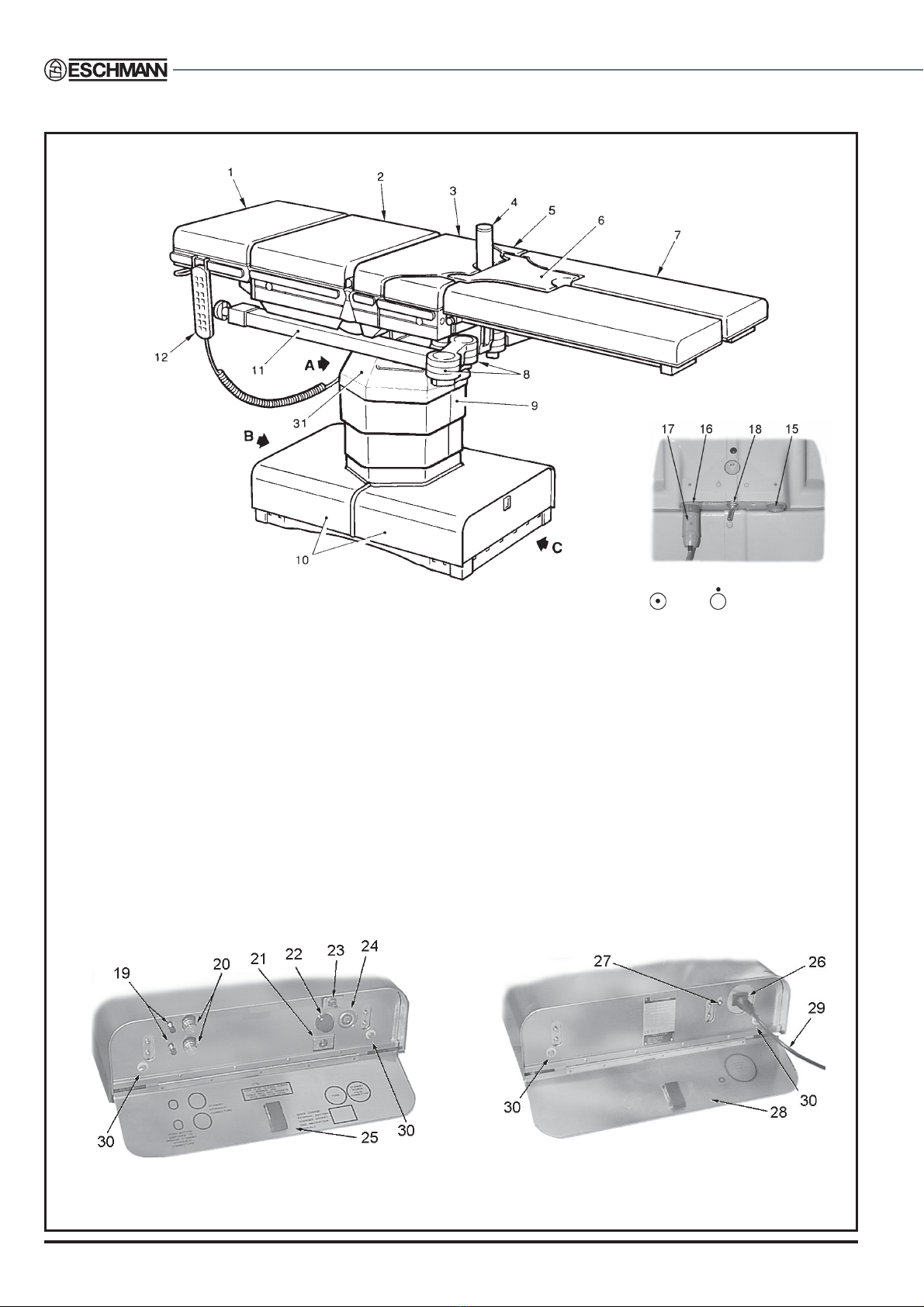
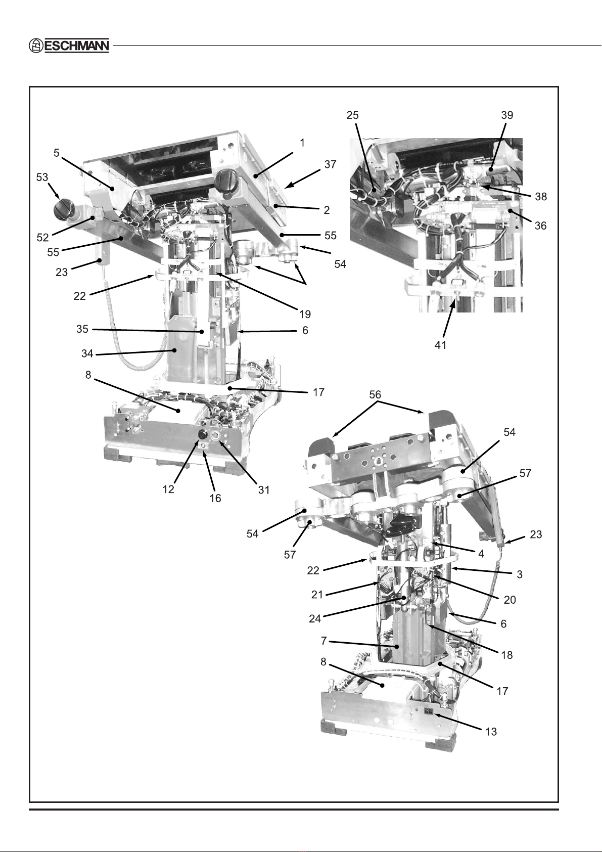
4. INTRODUCTION
Fig. 1 RX600 Powered OperationTable
1. Headsection
2. Long trunk section
3. Short trunk section
4. Perineal post
5. Hip section
6. Sacral extension
7. Pre-traction leg section
8. Traction beam swivel joints
9. Column cover
10. Table base covers
11. Traction beams
12. Hand control
15 Hand control/Footcontroller socket
16 Hand control/Footcontroller socket
17 Hand control plug
18 Table ‘on/off’ switch ( =on, =off)
19 Standby hydraulic power-pack pushbuttons
20 Standby hydraulic power-pack connectors
21 External battery charger socket
22 High current 30A Fuse
23 Door microswitch
24 External power-pack connector
25 Standby door
26 Internal battery charger socket
27 Internal battery charger 'on' indicator
28 Internal battery charger door
29 Removable mains lead
30 Cover retaining screws
31 Top of column covers
View on base long trunk end View on base short trunk end
View on ‘A’

T-SM14g 7/44
RX600RX600
RX600RX600
RX600
OPERATION TABLE
GENERAL
4.1 This Service Manual contains a technical
description and maintenance procedures for the RX600
Powered Operation Table as shown in Fig.1.
4.2 The table is a battery powered, mobile,
orthopaedic,andtrauma tablewith twointegralarticulated
telescopic traction beams, which stow under the table-top
whennotin use. Thebeams are extended foruse,and are
used in conjunction with traction accessories. The table-
topcomprisespre-tractionlegsupports,and head,hip,long
and short trunk sections.
4.3 The table can be used as a general purpose five-
section Operation Table, by fitting optional infill sections,
and an optional leg section, in place of the pre-traction leg
supports.The tabledesignallowsafull rangeoforthopaedic
andtraumasurgicalprocedurestobe carried out,including
pin and plate femur and tibia nailing, and arm traction.
4.4 The table is operated by electrical/electronic
circuits, which control the position of hydraulic cylinders
(viaelectro-hydraulicvalves) inresponseto signals froma
touch-button hand control, or from an optional footswitch.
The hand control and the footswitch both plug into
connectors at the top of the table column.
4.5 Power is provided by two 12V sealed lead-acid
batteries inthe tablebase.The 12Vbatteriesare connected
in series to give an output voltage of 24V.Trickle charging
for the batteries is provided by an inbuilt battery charger,
provisionis alsomade for connectionofanexternal battery
chargerforquick battery charging.Connectionof theinbuilt
battery charger to the mains electrical supply is via a
removable cable which plugs into the table base.
4.6 All table top trunk movements are electrically
controlled using either the hand control or, as an optional
accessory, the footswitch which is used by the surgeon
during certain procedures for height and Trendelenburg
control.
4.7 The main operation table sections are:
?Base.
?Central column.
?Head section.
?Long and Short trunk sections.
?Hip section.
?Sacral extension.
?Pre traction leg section.
?Traction accessories.
NOTE: Instruction and Service manuals should he readily
accessible for reference prior to, and when operating,
cleaning and servicing the table.
ELECTRICAL SYSTEM
NOTE: Electrical/electronic circuit diagrams are provided
at the end of this Manual in section 6.
Main control board
4.8 The main control board receives signals from the
hand control via an RS485 serial communication link.The
boardalso receivessignals fromthe footswitch,table-base
coverswitches,levellingmicroswitches,level tiltswitch,opto
board,standbyunitsocket,doorswitch,tractionbeam opto
sensors and table base on/off controls.
4.9 Outputs from the main control board pass to the
hand control via an RS485 serial communication link, to
thehydraulic solenoidsviathetop-of-columndistributorand
solenoidboards,and tothe basedistributorboardand FET-
Relay board for motor on/off control and motor direction
control. The main control board is supplied with 24V d.c.
from the batteries and generates its own 12V d.c.and 5V
d.c.supplies.
4.10 The principal functional areas of the main control
board are:
?Input buffering (pull-up and pull-down resistors and
capacitors).
?The microcontroller, which uses software to
implement table control functions.
?Output buffering (current drivers and level shifters).
?Motor direction drive and on/off control.
Height opto board
4.11 The height opto board is fitted at the base of the
column in a fixed position relative to the baseplate. It
responds to a metal reflector plate which moves up and
down with the column chassis and hence with the table
top.When thereflector movesinfront of thethree reflective
opto sensors (only two are used) electrical signals are
generatedto signal tothe main controlboardthat the table
is at or above‘minimum height’, or in the‘castor’position.
4.12 Whenthe reflectorplate isinfrontofreflectiveopto
coupler 01 and at the correct distance from it, a signal is
produced which passes via J1 on the opto board and the
10-way ribbon cable to J22 on the main control board.
4.13 Whenthe reflectorplate isinfrontofboth reflective
optocouplers 01and03 signalsfrom bothpass tothemain
controlboardwhichstopsthe tablemovement atthecorrect
position.
4. INTRODUCTION

8/44 T-SM14g
Base distribution board
4.14 This board receives signals from the main control
boardfortheheight(extend)solenoid,theheight (contract)
solenoid, the pump-isolate (forward) solenoid and the
pump-isolate (reverse) solenoid.
4.15 The board also passes signals to the main control
board from the cover microswitches.
4.16 Any inductive overswings from the solenoids are
blocked by diodes Dl to D4. PL7 on the base distribution
board is connected via a 14-way ribbon cable to J4 on the
main control board.
Top-of-column distribution board
4.17 This board connects to J2 on the main control
board via a 34-way retractable ribbon cable which
terminates on PL1
of this board. It distributes signals to
10-way hand control/footswitch sockets PL2 and PL3, and
to:
?the level tilt switch via PL7
?theTrend level position microswitch via PL5
?the lateral tilt opto board via PL4
?the break level position microswitch via PL6
?top-of-column solenoids board via PL8
?the on/off switch via PL9
?proximity sensors on long trunk via J10/11/12.
Top-of-column solenoids board
4.18 This board receives signals on J7 via a 10-way
ribboncablefromJ8 onthe top-of-columndistributorboard
to drive the top-of-column solenoids via cage clamp
connectors J1 to J6. It also blocks inductive overswings
from solenoids using diodes D1 to D6.
Tilt opto board
4.19 Thetiltopto board is fittedat the top ofthecolumn
ina fixed positionrelativeto theyoke.It respondsto ametal
plate which moves with the yoke and hence with the table
top.When the reflector moves in front of the opto sensors
electrical signals are generated to signal the main control
board that the table is level.
4.20 When the reflector plate moves in front of the
optosensor,alogicsignal0isproducedwhichpasses
via J1 on the opto board to the top of column
distributionboard and thenvia a10-way ribboncable
to J2-4 on the main control board.
4.21 When the reflector plate is not in front of the
opto sensor, a logic signal 1 is produced which is
passed to the main control board as above.
4. INTRODUCTION
Power circuits
4.22 The power source for the table is two 12V, 24Ah
sealed lead acid batteries connected in series. A 30A in-
line, high current fuse protects the batteries, motor, FET
relay board and interconnections.
4.23 Currentfrom thebatteries passesvia thereversing
relay, where itisswitched bythe FET’s,and thenpasses to
the pump motor and returns to the batteries.The 24V d.c.
supply is also routed to the hydraulic solenoids and the
main control board.
Hand control
4.24 The RX600 hand control communicates with the
maincontrol boardviaanRS485serialcommunicationlink.
Thehand controlcontainsamicrocontrollerwhich receives
inputsfrom thehand controlbuttonsandgeneratesoutputs
which go to the hand control LED’s and the hand control
audiblewarning device.The microcontrolleruses software
to implement hand control, control functions.
4.25 Thehand-control incorporatesa 2-digitdisplaythat
indicatesacode if aproblemshould occur.Such problems
couldbe theresult ofthe userpushingabuttonin thewrong
sequence or at the wrong time or of a system failure (see
Table1- FaultDiagnosis,Table2 -Codesfor2-Digitdisplay
and Fig. 31)
Footswitch (optional accessory)
4.26 The footswitch plugs into either of the two 10-way
sockets used by the hand control. It uses the same +5V
d.c.and0V pins,butthesignallinesaredifferent fromthose
of the hand control. The footswitch does not use a serial
communication link.
4.27 There are four functions on the footswitch:
?Height up.
?Height down.
?Trendelenburg.
?ReverseTrendelenburg.
4.28 Eachof thesefourfunctionsis associatedwithtwo
microswitches mounted inside the body of the footswitch,
one normally open and the other normally closed. The
normally open microswitch for each function is connected
on one side to the +5V d.c. line and on the other side to a
common ‘alarm’ line.The normally closed microswitch for
each function is connected on one side to the 0V line and
on the other side to an individual input line on the main
controlboard.If,foranyfunctionof thefootswitch,e.g.height
up, the normally open microswitch operates and the
normally closed microswitch does not, or vice versa, the
main control board will recognise a fault and freeze the
table.Thelikelihoodoftwo microswitches failingatthesame
time is very remote.

T-SM14g 9/44
RX600RX600
RX600RX600
RX600
OPERATION TABLE
4. INTRODUCTION
Table base ON/OFF control
4.29 The table is switched‘on’and ‘off’ by selecting
and respectively.Whenswitched‘on’,24Vd.c.isswitched
directly to the main control board.When it is switched ‘off’
themaincontrol board isisolated from the24Vd.c.supply.
To isolate the system the 30Amp fuse should be removed.
Built-in battery charger
4.30 Thisis ainternallowcurrentoutput‘trickle’charger,
which replenishes an average day’s table use of the
batteries with an overnight charge.
4.31 The mains input comes via the mains lead, which
shouldbe fittedwitha fusedplug.The outputof thecharger
is regulated to provide 27.6V d.c.to the batteries for float
charging. This voltage will fall when the batteries are not
completely charged and hence are drawing a significant
current. The charger has short-circuit and thermal
protection.Thereisanoutputfromthe boardwhichsupplies
current to the batteries, an output to the ‘trickle’ charger
indicator LED and an input from the external charger.
Current from either the internal or the external charger is
routed to the batteries via the ‘trickle’charger board.
External battery charger (optional accessory)
4.32 Theexternal batterychargerplugsintothe external
battery charger socket in the table base and supplies
current via the ‘trickle’ charger board to fast-charge the
batteries.
Standby system connections
4.33 An RX Standby Unit (optional accessory) which
provides standby hydraulic and electrical services, can be
connectedto theRX600 tablevia hydraulicconnectorsand
an electrical socket behind a door on the table base.
4.34 Next to the hydraulic connectors are two push-
buttons which release stored hydraulic pressure when the
standby hydraulic connections are first made.This is done
byenergizingthe pumpforwardandreversesolenoidswith
power from the standby unit.
4.35 To connect the standby unit to the table it is
necessary to open the base door. This operates a
microswitch which disconnects the main control board
solenoid control circuits from the solenoids so that they
canbecontrolled bythe standbyunit, alsothepump motor
is hydraulically isolated from the hydraulic solenoids.The
electrical signals from the standby socket pass to J1 on
the main control board (15-way D-connector).
Traction beam stowage detection
4.36 Proximitysensorsfittedintheunderside ofthe long
trunk section detect the traction beams when they are in
their stowed position. The sensors signal the table control
system to stop the table top being driven down onto the
stowed traction beams.
10/44 T-SM14g
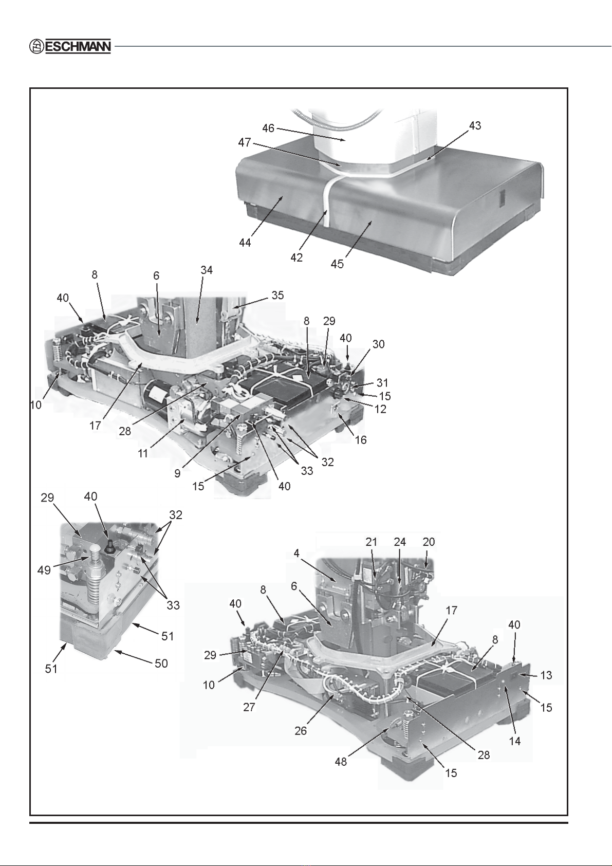
5. DESCRIPTION
Fig. 2 RX600 Operation Table : Base details, covers on and off
For greater detail of
the table base ends also
refer to Fig. 4 and 5

T-SM14g 11/44
RX600RX600
RX600RX600
RX600
OPERATION TABLE
5. DESCRIPTION
1. Longtrunk assembly
2. Short trunk assembly
3. Lateral tilt cylinder
4. Wraparound
5. Trunk assembly plastic covers
6. Wedge
7. Outercolumn
8. Battery
9. Manifold block No 1
10. Castor plateguidepillar
11. Hydraulic powerunit
12. High current fuse,30A
13. Mains socket
14. Battery chargingLED(green)
15. Cover retainingscrewlocation
16. External battery charger socket
17. Dripgutter
18. Opto reflectorplate
19. Inner column
20. Manifold block No 4
21. Manifold block No 3
22. Upperbezel
23. Hand controlandcable
24. Trendelenburgcylinder
25. Break cylinders
26. Main control PCB
27. Base distribution PCB
28. Castor frameassembly
29. Manifold block No 2
30. Door microswitch
31. Standby powerpackconnector
32. Standby hydraulicconnectors
33. Push buttons to engage standby
hydraulicconnectors
34. Hydraulicreservoir
35. Ribbon cablereelassembly
36. Top-of-columndistributionPCB
37. Hinge
38. Lateral tiltoptoboard
39. Yoke
40. Cover microswitch
41. Table‘on/off’switch
42 Base seal
43. Column seal
44. Short trunk base cover
45. Long trunkbasecover
46. Telescopic column cover
47. Columnupstand
48. Antistatic discharge path resistor
49. Base cover spring support
50. Base foot
51. Base skirt
52. Traction arm selector knob
53. Tractionhandle
54. Swivel joint, knuckle
55. Tractionarm
56. Hip section
57. Swivel joint locking knob
Key to Figs 2 and 3
12/44 T-SM14g
5. DESCRIPTION
Fig. 3 RX600 OperationTable : Column and trunk section detail
T-SM14g 13/44
RX600RX600
RX600RX600
RX600
OPERATION TABLE
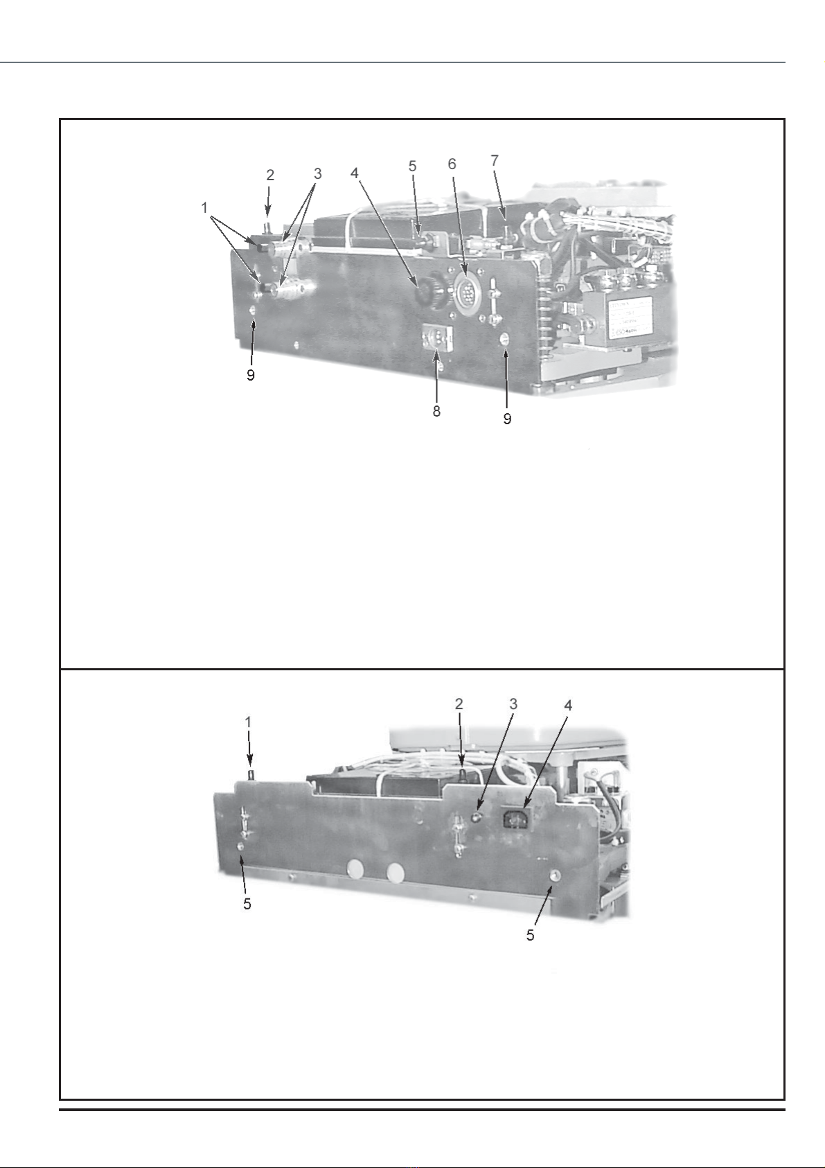
Fig. 5 RX600 OperationTable base detail (short trunk end)
1 Standby hydraulic push buttons
2 Base cover microswitch
3 Standby hydraulic connectors
4 High current (30A) fuse
5 Door Microswitch
6 Standby power pack connector
7 Base cover microswitch
8 External battery charger socket
9 Fixing for cover retaining screw
Fig. 4 RX600 OperationTable base detail (long trunk end)
1 Base cover microswitch
2 Base cover microswitch
3 Mains charging LED
4 Mains connection socket
5 Fixing for cover retaining screw
5. DESCRIPTION
14/44 T-SM14g
GENERAL
6.1 Maintenance of the RX600 Powered Operation
Table falls into the following categories:
Cleaning and storage. Adjustments.
General care and lubrication. Removaland Installation.
Functional checks. Fault diagnosis.
Hydraulic system.
CLEANING AND STORAGE
WARNING
Always switch off table at table ‘ON/OFF’
switch (item 18, Fig. 1) prior to cleaning.
6.2 For cleaning and storage instructions refer to
RX600 Powered Operation Table Instruction for Use
(Publication No.T-IM33 issue‘d’or later).
6.3 For cleaning and storage instructions of the table
accessories refer to the Accessory Instructions for Use
(PublicationNo.T-IM56).
Note: If the table is to be stored for any length of time the
head and leg sections should be fully lowered. This is
necessary to ensure that the gas spring seals and pistons
are kept fully lubricated.
GENERAL CARE AND LUBRICATION
6.4 Once a week proceed as follows:
Gas Springs
WARNING
The gas springs are filled with high pressure
gas. Do not attempt to open them.
CAUTION
Gas springs MUST NOT be
additionally lubricated.
6.5 The gas spring supports for the head section are
sealed units which require no routine maintenance.
Malfunction of a gas spring makes it impossible to lock the
headsection inposition.Seepage offluidindicates afailing
unit.
6.6 If a gas spring is faulty, the complete unit must be
renewed,gassprings arenon-repairableitems(seesection
6.44).
Head, hip, pre-traction leg support and
alternative leg sections, and sacral extension
6.7 Service thehead,hip,andpre-tractionlegsupport
sections, and sacral extension as follows:
i Apply a smear of light machine oil to the guide pins
and pivot pins on the head, hip, and pre-traction leg
sections, and the Sacral extension.
ii Examine all sections, and the sacral extension for
signs of damage, particularly for scoring or bending
of the attachment guide pins. On the head and
alternative leg section, examine the release handle
for signs of damage.
iii Check the guide pin retaining screw for tightness.
iv On the head and alternative leg section, check the
hingeand gasspringpivotsforsecurity (grubscrews
or starlock washers, whichever fitted), particularly
the main hinge pivot pin. (Note that the grub screw
for the main hinge pivot pin is underneath the
radiographictop.)
v Check the side bars for security.
vi Examinethe guidepinlockingbuttonon thehip,and
pre-traction leg support sections, and the release
latch on the Sacral extension for damage. Apply a
smear of light machine oil to all moving parts.
vii On the infill section, examine the guide pin locking
button devices for damage and ensure that the
mechanism, which prevents removal of the infill
section before any attached section has been
removed, functions correctly (refer to section 6.49).
Applyasmearoflight machineoil toallmoving parts.
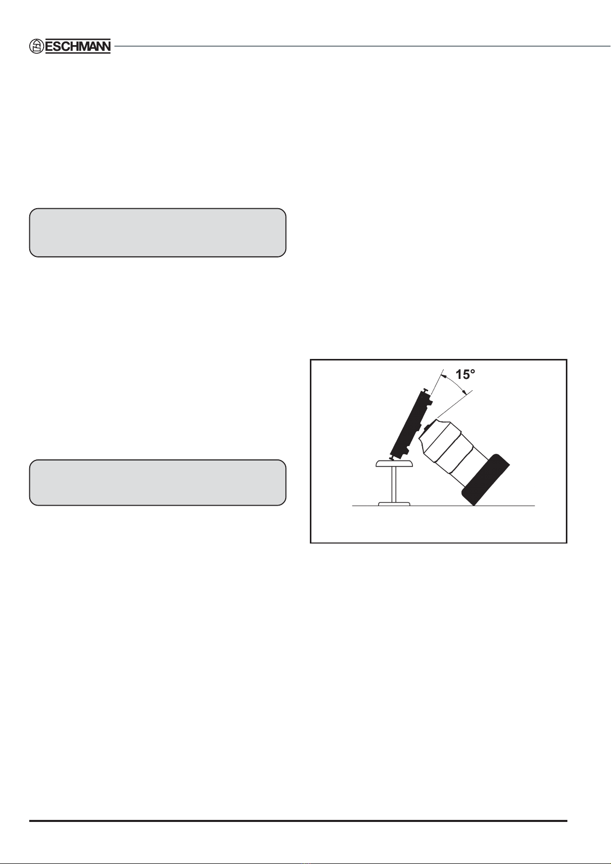
Fig. 6 Table tilted for access to underside
Head and hip sections, locking mechanisms
6.8 Remove the head, hip and sacral extension
sections from the table and clean out any collected fluff or
otherdebris fromguidepin sockets in theends of thetrunk
sections, in the sacral extension attachment and location
holesinthe crossbeam.Spraya little aerosollubricant into
each socket and attachment hole. Check the operation of
the locking mechanisms when re-attaching the sections
(for adjustment refer to section 6.50).
Long and short trunk sections
6.9 Service the long, and short trunk sections as
follows:
i Apply a smear of light machine oil to the pivot pins
on the long and short trunk sections.
ii Examine the guide pin button locking devices for
damage(foradjustmentrefer to section6.50).Apply
a smear of light machine oil to all moving parts.
6. MAINTENANCE
T-SM14g 15/44
RX600RX600
RX600RX600
RX600
OPERATION TABLE
Radiographic tops
6.10 Examine the radiographic tops for cracks, chips
and scoring. Significant damage will necessitate
replacement of the damaged section. Make sure that the
radiographic tops are securely attached (not applicable to
the optional leg section).
Underside of the table base
6.11 To maintain the underside of the table base, it is
necessary to tilt the table onto its side as follows:
i Ifnecessary, removehead, andpre-traction legand
support sections or the leg and infill section
accessories.
ii Usingthehandcontrol,raisethetabletoitsmaximum
height and make sure that the long and short trunk
sections are level.
iii Using the hand control, set the table top to the
maximum lateral tilt position corresponding to the
directioninwhich the tableistobe tilted (seeFig.6).
iv Place an anaesthetist’s stool, or a similar strong
support,along onesideof thetable(seeFig.6).With
two people standing on the same side of the table
as the support (one at each end), tilt the table over
and gently lower it onto the support, making sure
that it rests on the side bars of the long and short
trunk sections.
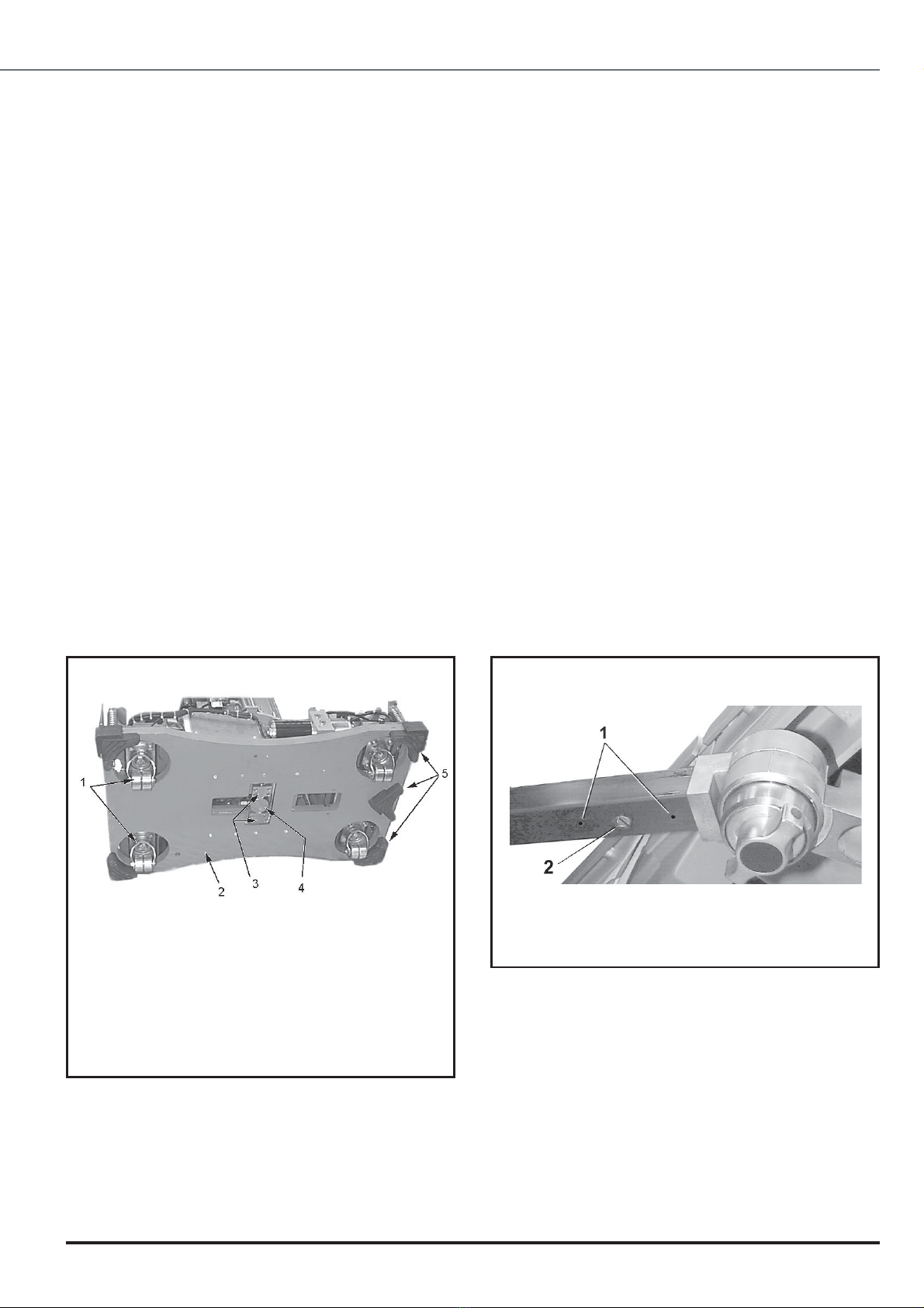
1 Castor assembly
2 Table base plate
3 Height cylinder pivot clamp blocks
4 Height cylinder
5 Base feet
Fig. 7 Underside of table base
6.12 With the table in the tilted position, proceed as
follows (see Fig.7):
i Examinethefive basefeet for damage orexcessive
wear.Ifnecessary, replacethe appropriatebase feet
as described in sections 6.47 and 6.48.
ii Clean each castor assembly making sure that they
are free of dust and debris. Lubricate the bearings
of each castor and the directional wheel with a light
machine oil.
iii On completion, return the table to the upright
position.
Traction beam attachment
6.13 Routine maintenance of the beam attachment
consistsofchecking for secure attachmentof the beam as
follows:
i Remove the two locking socket set screws (items 1,
Fig.8) from the underside of the beam.
ii Two socket dog point set screws under the two
locking socket set screws removed in (i) above can
now be checked and tightened.
iii Replace and tighten the two locking socket set
screws removed in (i) above.
iv Check and tighten the slotted countersunk screw
(item 2, Fig. 8).
Fig. 8 Adjustment of beam attachment
6. MAINTENANCE
16/44 T-SM14g
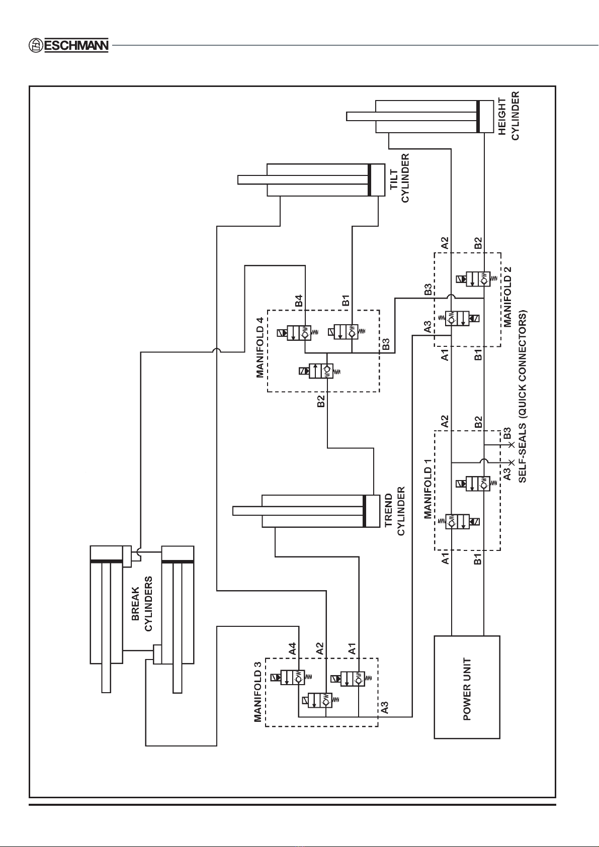
Fig. 9 Hydraulic system - Schematic diagram
T-SM14g 17/44
RX600RX600
RX600RX600
RX600
OPERATION TABLE
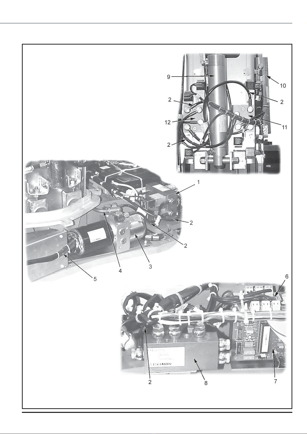
6. MAINTENANCE
1 Manifold1
2 Hydraulic connections
3 Power unit
4 Feed from reservoir
5 Power unit electrical lead
6 Base distribution board
7 Base control board
8 Manifold 2
9 Trendelenburgcylinder
10 Tilt cylinder
11 Manifold 4
12 Manifold 3
Fig. 10 Hydraulic system - main components
For break cylinders see Fig.18
and for height cylinder see Fig.22.
The lateral tilt cylinder is also
shown in greater detail in Fig.19.
Note: Hydraulic cylinder rams are
retractedwhenthe tabletopispositioned
as follows, but care must be taken when
movingthetableintothispositiontoavoid
damage, sections will be very close to
the floor :
Minimum height and onto castors.
Maximum extension achievable at the
minimum height set above.
Maximumtilt achievablewith tableatthe
minimumheightand extension setabove
(tilt table such that the right hand side is
lowered when viewed from short trunk
endoftable).
18/44 T-SM14g
Access to fuses
6.14 The high current 30A mains fuse is fitted in the
table base standby panel (item 4, Fig. 4).The three other
fuses for the operation table are fitted on the main PCB
(item 3, Fig.11) in the base of the table. To get to them
remove the base covers as described in section 6.26.The
installationofthe base coversis described insection6.27.
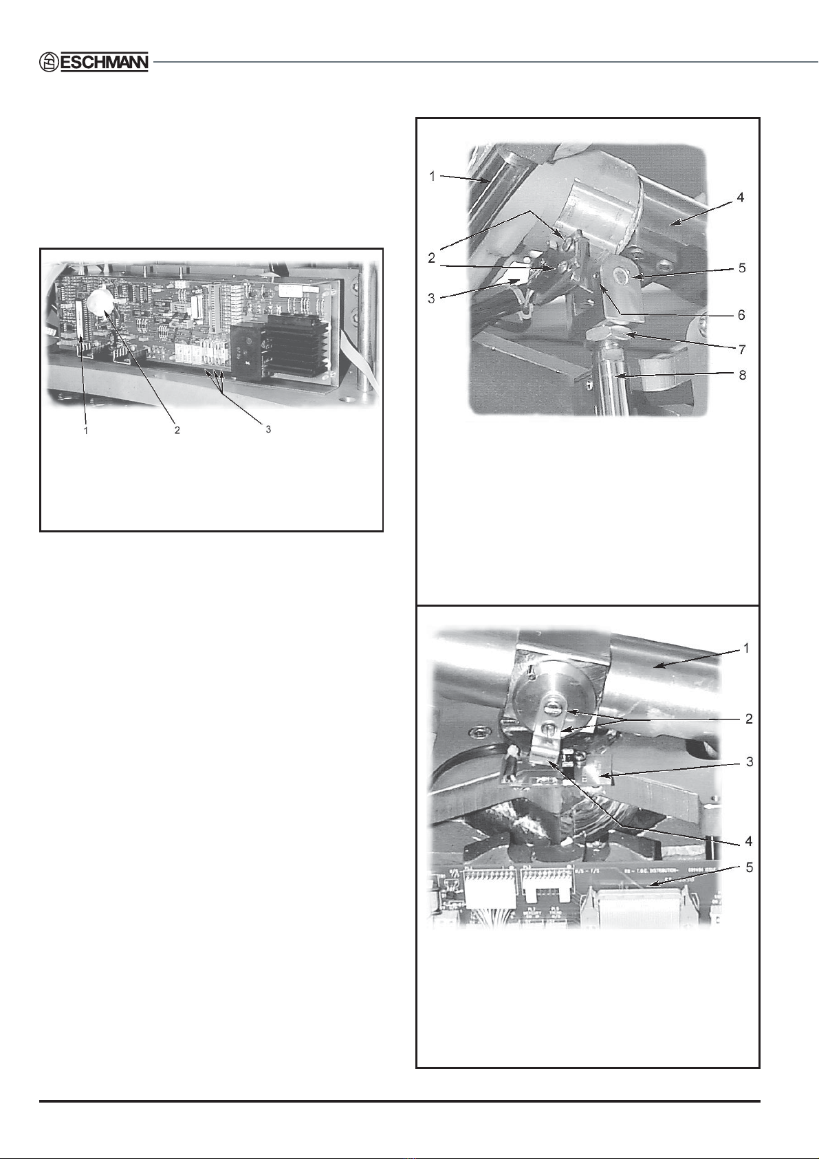
1 Programmed microcontroller
2 Beeper
3 Fuses
Fig. 11 Main control board
Hand control
6.15 The factory sealed hand control requires no
maintenance.If a faultissuspectedin thehandcontrol first
test all table functions using a hand control known to be
fault free. If a fault is confirmed with the hand control the
complete assembly (including lead and plug) should be
replaced (see Fig.31 for details of hand control function).
After maintenance
6.16 After maintenance on the operation table, always
check all functions (section 6.17) and lower the table fully.
FUNCTIONAL CHECKS
General
6.17 The following functional checks should be carried
out after maintenance of the operation table, or after
rectification of any faults:
i Refer to ManualT-IM33 issue‘d’or later, and check
the state of batteries using the hand control, codes
01 and 02 should not be displayed. If they are the
table batteries need recharging.
ii Using the hand control, check that all table
movements agree with theTechnical Data.
iii Using the foot control unit (optional accessory),
check that the table movements are correct for
Trendelenburg,ReverseTrendelenburg, and Height.
iv Usehandcontroltocheckoperationofthe‘auto level’
function.
6. MAINTENANCE
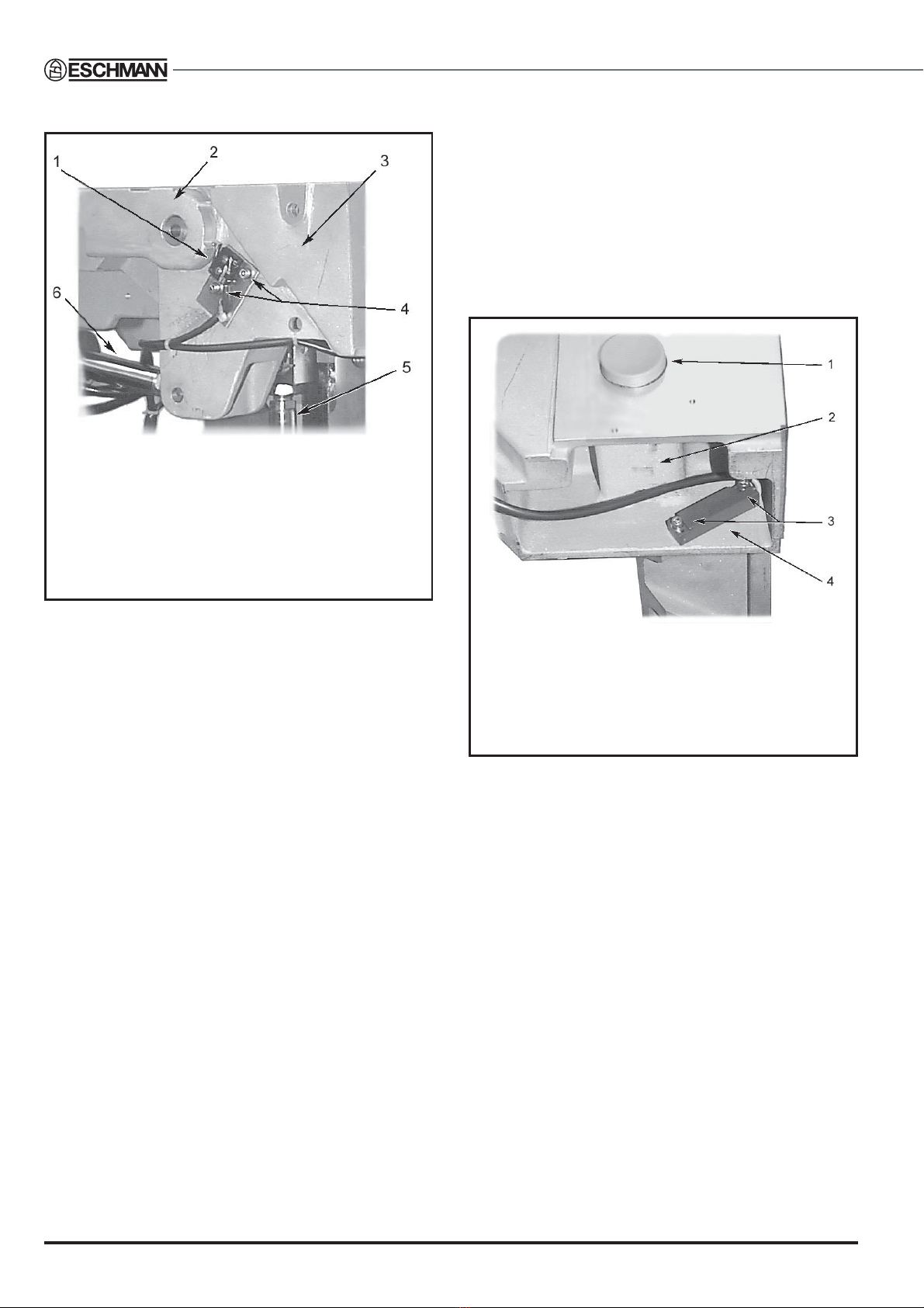
1 Breakcylinder
2 Microswitch adjusting screws
3 Trendelenburgmicroswitch
4Yoke
5 Pivot pin
6 Pivot pin set screw
7 Tilt cylinder ram lock nut
8 Tilt cylinder ram
Fig. 12 Trendelenburg microswitch
1Yoke
2 Adjusting screws
3 Lateral tilt opto board
4 Lateral tilt opto flag
5 Top of column distribution board
Fig. 13 Lateral tilt opto detail

T-SM14g 19/44
RX600RX600
RX600RX600
RX600
OPERATION TABLE
HYDRAULIC SYSTEM
CAUTION
Scrupulous cleanliness is essential to prevent
contamination of the fluid in the hydraulic
system.
Notes:
1 Use only Eschmann RX hydraulic oil, Part
No.699408, which is obtainable from Eschmann
Equipment or their accredited agents.Replace cap
on oil container after use.
2 When replacing hydraulic components all Banjo
fittingsmustbe tightenedto atorquesettingbetween
19 and 21 Nm.
3 The hydraulic system schematic diagram is shown
inFig.9 withthemain components illustratedin Fig.
10. Individual cylinders are also shown in the
‘RemovalandInstallation’section laterinthemanual.
General
6.18 Ifthetablecannotbeplacedintothe castorposition
using the hand control, it may be necessary to manually
raise the table base. To raise the table base, proceed as
follows:
i Remove table base covers, see section 6.26
ii Locate the jacking nut at each corner of the table
base (see Fig.26, item 1) and wind the nuts down
evenly to raise the table base.
Topping-up the hydraulic reservoir
6.19 Top-up the hydraulic reservoir as follows:
i Set table to an appropriate height and remove base
covers as described in section 6.26.
ii Release the central column cover and remove the
upstand as described in section 6.30.
iii Retract all cylinder rams before filling reservoir so
thatthe trueoillevel canbeestablished(seeNote in
Fig.10).Overfilling could damage the reservoir.
iv Remove the filler cap from the hydraulic reservoir
andfill the reservoirwith EschmannRX hydraulicoil
until oil level is 13 mm below the filler hole of the
reservoir.
v Refit the filler cap on reservoir.
vi Refit the central column cover and upstand as
described in section 6.31.
vii Refit the base covers as described in section 6.27.
ADJUSTMENTS
Trendelenburg (Trend) microswitch
6.20 Tocheckandadjust theTrendelenburgmicroswitch
(item 3, Fig.12) proceed as follows:
i Ensure the table is on a level surface.
ii Using the hand control, move the table top to the
maximumTrendelenburgposition.
iii Onthe handcontrol,pressthe‘autolevel’buttonand
wait until the table top stops when level.
iv Using an inclinometer (on section radiopaque top
notthemattress), checktheangle of theshorttrunk
section in the horizontal plane.
v If the angle is more than one degree out in either
direction adjust the Trendelenburg microswitch as
necessary, by releasing the adjusting screws
(item 2, Fig.12) and moving the microswitch in the
appropriatedirection,retightentheadjustingscrews.
vi Repeat steps‘ii-v’until the short trunk section stops
level.
Lateral tilt opto
6.21 Tocheck andadjustthelateraltiltoptoflag(item 4,
Fig.13) proceed as follows:
i Ensure the table is on a level surface.
ii Using the hand control, tilt the table top to the
maximum lateral tilt position (left or right).
iii Onthe handcontrol,pressthe‘autolevel’buttonand
wait until the table top stops when level.
iv Using an inclinometer (on section radiopaque top
notthemattress), checktheangle of thetable top in
the lateral plane.
v If the angle is more than one degree out in either
directionadjust theflag (item4,Fig.13)for thelateral
tilt opto by releasing the adjusting screws (item 2,
Fig.13) and moving the flag in the appropriate
direction, retighten adjusting screws.
vi Repeat steps‘ii-v’until the table stops level.
Break microswitch
6.22 Tocheck andadjust thebreak microswitch (item 1,
Fig.14) proceed as follows:
i Ensure the table is on a level floor.
ii On the hand control, press the break (extension)
buttonandmovethetabletop tothe maximumbreak
(extension)position.
iii Onthe handcontrol,pressthe‘autolevel’buttonand
wait until the table top stops when level.
6. MAINTENANCE
20/44 T-SM14g
1 Breakmicroswitch
2 Long trunk assembly
3 Short trunk assembly
4 Adjusting screws
5 Tilt cylinder ram
6 Break cylinder ram
Fig. 14 Break microswitch
iv Using an inclinometer (on section radiopaque top
notthemattress), checkthat the short trunksection
is level, if it is not adjust the Trendelenburg
microswitch as detailed in section 6.20.
v Using an inclinometer (on section radiopaque top
not the mattress), check the angle of the long trunk
section.
vi If the angle is more than one degree out in either
direction adjust the break microswitch by releasing
the adjusting screws (items 4, Fig.14) and moving
themicroswitchintheappropriatedirection, retighten
the adjusting screws.
vii Repeat steps‘ii-vi’until the long trunk section stops
level.
Level tilt switch
6.23 To adjust the level tilt switch (item 4, Fig.15)
proceed as follows:
i Ensure the table is on a level floor.
ii Onthe handcontrol,pressthe‘auto level’buttonand
wait until the table top stops when level (check the
long and short truck sections are level in both
directions and adjust if required as detailed in
sections 6.20 to 6.22).
6. MAINTENANCE
iii On the hand control, press patient right orientation
button (button 2, Fig.31).
iv Onthehand control,press theTrendelenburgbutton
(button 3, Fig.31) and move the table top to the
maximum reverseTrendelenburg position.
v Using an inclinometer (on the radiopaque top not
the mattress of the short trunk section), check the
angle of the table top. The angle should be 35
degrees.
1 Push button
2 Short trunk assembly
3 Adjusting screws
4 Level tilt switch
Fig. 15 Level tilt switch
vi On the hand control, press the break (extension)
button(button 5, Fig.31)andcheckfor movement of
the long trunk section of the table top.If movement
occurs, adjust the level tilt switch by releasing the
adjusting screws (item 3, Fig.15) and moving the
level tilt switch in the appropriate direction to stop
anymovement ofthelongtrunk sectionwith thetable
top in the reverseTrendelenburg position.
vii Afteradjustingthe leveltilt switch repeat actions(iv)
(v) and (vi) until there is no movement of the long
trunksection inthemaximumTrendelenburgposition.
Table of contents
Other eschmann Medical Equipment manuals


Popular Medical Equipment manuals by other brands


Getinge
Getinge Arjohuntleigh Nimbus 3 Professional Instructions for use

Mettler Electronics
Mettler Electronics Sonicator 730 Maintenance manual

Pressalit Care
Pressalit Care R1100 Mounting instruction

Denas MS
Denas MS DENAS-T operating manual

bort medical
bort medical ActiveColor quick guide

AccuVein
AccuVein AV400 user manual


