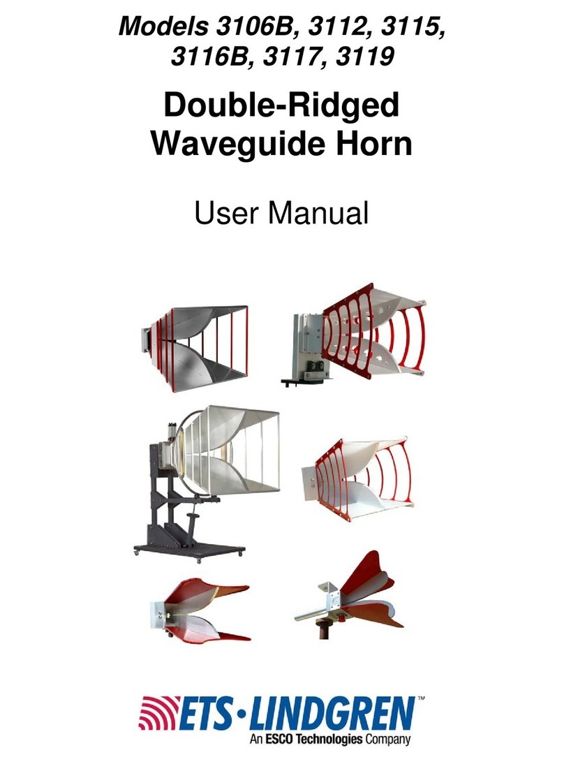
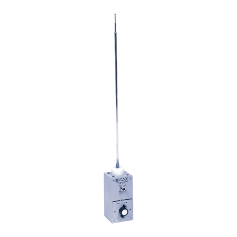
Esco ETS-Lindgren 3117 User manual

Model 3117
Double-Ridged
Waveguide Horn
User Manual

ETS-Lindgren reserves the right to make changes to any products herein to improve functioning
or design. Although the information in this document has been carefully reviewed and is believed
to be reliable, ETS-Lindgren does not assume any liability arising out of the application or use of
any product or circuit described herein; nor does it convey any license under its patent rights nor
the rights of others. All trademarks are the property of their respective owners.
©Copyright 2003-2006 by ETS-Lindgren L.P. All Rights Reserved. No part of this document
may be copied by any means without written permission from ETS-Lindgren L.P.
Trademarks used in this document: The ETS-Lindgren logo are trademarks of ETS-Lindgren, L.P.
Revision Record
MANUAL, 3117, Part #399278, Rev. B
Revision Description Date
A Initial Release September, 2003
B Modified mounting bracket diagram, mounting
instructions, VSWR data, product photo October, 2006
Internet Address
http://www.ETS-Lindgren.com
USA
1301 Arrow Point Drive
Cedar Park, TX 78613 USA
Tel: +1.512.531.6400
Fax: +1.512.531.6500
Email: [email protected]
Finland
Mekaanikontie 1, 27510
Eura, Finland
Tel: +358.2.838.330
Fax: +358.2.865.1233
Email: [email protected]
Japan
4-2-6, Kohinata
Bunkyo-ku, Tokyo 112-0006 Japan
Tel: +81.3.3813.7100
Fax: +81.3.3813.8068
Email: [email protected]
China
B507A Technology Fortune Center
No. 8 Xue Qing Road
Haidian District
Beijing Postcode: 100083 China
Tel: +86.010.827.30877
Fax: +86.010.827.55307
Email: [email protected]
ii |

Table of Contents
Safety Symbol Definitions.................................................................................................................v
General Safety Considerations.........................................................................................................v
1.0 Introduction................................................................................................................................7
1.1 Standard Configuration.......................................................................................................... 7
2.0 Receiving Your Order................................................................................................................ 9
2.1 Unpacking and Acceptance................................................................................................... 9
2.2 Return Procedures................................................................................................................. 9
3.0 Maintenance............................................................................................................................ 11
4.0 Mounting Instructions .............................................................................................................. 13
4.1 Using the Mounting Bracket................................................................................................. 13
4.1.1 Mount the Bracket onto a Tripod................................................................................... 14
4.1.2 Mount the Bracket onto an ETS-Lindgren Tower Boom............................................... 14
4.1.3 Attach the Antenna to the Mounting Bracket ................................................................ 14
4.2 Using the Stinger Mount...................................................................................................... 14
4.2.1 Mount the Antenna into the Stinger Mount Boom......................................................... 14
4.2.2 Mount the Antenna into a Clamp Block......................................................................... 14
4.3 Attach a Cable to the Type N Connector............................................................................. 15
5.0 Application............................................................................................................................... 17
6.0 Typical Data............................................................................................................................. 19
6.1 Model 3117 Antenna Factor at 1 Meter............................................................................... 19
6.2 Model 3117 Gain.................................................................................................................. 19
6.3 Model 3117 VSWR .............................................................................................................. 20
6.4 Model 3117 Half Power Beamwidth..................................................................................... 20
6.5 Model 3117 Forward Power at 1 Meter 1V/m to 10V/m ...................................................... 21
6.6 Measured Radiation Pattern................................................................................................ 22
7.0 Specifications .......................................................................................................................... 27
7.1 Electrical Specifications....................................................................................................... 27
7.2 Physical Specifications ........................................................................................................ 27
8.0 Warranty Policy for Standard EMCO Brand Products............................................................. 29
8.1 Scope and Duration of Warranties....................................................................................... 29
8.2 Warranty Exclusions............................................................................................................ 29
8.3 Buyer’s Remedies................................................................................................................ 30
| iii

This page intentionally left blank.
iv |

Safety Symbol Definitions
This product and related documentation must be reviewed for familiarization with
safety markings and instructions prior to operation of the product.
Safety Symbol Definition
!
OR
REFER TO MANUAL—When the product is marked with this symbol
refer to the instruction manual for additional information. If the
instruction manual has been misplaced, go to www.ets-lindgren.com for
downloadable files or contact ETS-Lindgren customer service.
General Safety Considerations
Safety Symbol Definition
WARRANTY
BEFORE SERVICING: CONTACT ETS-LINDGREN
(+1.512.531.6400)—Servicing or modifying the unit without
ETS-Lindgren authorization may void your warranty. If an attempt to
service the unit must be made, disconnect all electrical power prior to
beginning. Voltages exist at many points within the instrument that
could, if contacted, cause personal injury. Only trained service
personnel should perform adjustments and/or service procedures upon
this instrument. Capacitors inside this instrument may still be charged
even when the instrument is disconnected from the power source.
ONLY QUALIFIED PERSONNEL should operate or service this
equipment.
| v

This page intentionally left blank.
vi |

1.0 Introduction
The ETS-Lindgren Model 3117 Double-Ridged Waveguide Horn Antenna is a
linearly polarized broadband antenna covering the 1 to 18 GHz frequency range.
The Model 3117 antenna was designed and built specifically for EMI
measurements and specifications compliance testing. However, it can also be
used for antenna gain, pattern measurement, surveillance, and other
applications.
A single well-defined main lobe radiation pattern over the entire frequency range
provides excellent illumination of the EUT. The Model 3117 antenna is ideally
suited for IEC61000-4-3 and MIL-STD 461/462 immunity tests as well as ANSI
C634 and EN 55033 emissions tests.
The Model 3117 antenna is precision machined from aluminum. A 50-ohm
precision high frequency type N connector is mounted on the base block of the
antenna. A mounting bracket is provided for tower and tripod mounting in
horizontal and vertical polarization positions.
1.1 Standard Configuration
• Antenna assembly
• Mounting bracket configured to accept ETS-Lindgren or other tripod mounts
with ¼ inch x 20 threads. In addition to the mounting bracket, a stinger mount
is provided for on-axis rotation during polarization.
• Individually calibrated at 1 meter per SAE ARP 958 at the ETS-Lindgren
A2LA accredited calibration lab. A 3-meter calibration per ANSI C63.5 is
available at additional cost. Actual antenna factors and a signed Certificate of
Calibration Conformance are included.
Introduction | 7

This page intentionally left blank.
8| Introduction

2.0 Receiving Your Order
2.1 Unpacking and Acceptance
Step 1. Upon delivery of your order, inspect the shipping container(s) for
evidence of damage. Record any damage on the delivery receipt before signing
it. In case of concealed damage or loss, retain the packing materials for
inspection by the carrier.
Step 2. Remove the product from its shipping container(s). Save the container(s)
and any protective packing materials for future use.
Step 3. Check all materials against the packing list to verify that the equipment
you received matches what was ordered. If you find any discrepancies, note
them and call ETS-Lindgren Customer Service for further instructions.
Ensure that you are satisfied with the contents and condition of your order prior
to placing the product into service.
2.2 Return Procedures
To return a system or system component:
Step 1. Contact ETS-Lindgren Customer Service to obtain an SRO, Service
Request Order.
Step 2. Briefly describe the problem in writing. Give details regarding the
observed symptom(s) or error codes, and whether the problem is constant or
intermittent in nature. Please include the date(s), the service representative you
spoke with, and the nature of the conversation. Include the serial number of the
item being returned.
Step 3. Package the system or component carefully. If possible, use the original
packing materials to return a system or system component to ETS-Lindgren at
the following address:
ETS-Lindgren
Attn. Service Department
301 Arrow Point Drive
Cedar Park, TX, USA 78613
Phone: +1.512.531.6400
Receiving Your Order | 9

This page intentionally left blank.
10 | Receiving Your Order

3.0 Maintenance
To ensure reliable and repeatable long-term performance, annual recalibration of
your antenna by ETS-Lindgren experienced technicians is recommended. Our
staff can recalibrate almost any type or brand of antenna. Please call to receive a
Service Order Number prior to sending an antenna for calibration.
For more information about our calibration services, visit our website at
http://www.ETS-Lindgren.com.
Maintenance | 11

This page intentionally left blank.
12 | Maintenance

4.0 Mounting Instructions
The Model 3117 Double-Ridged Waveguide Horn Antenna includes these
components:
• Double-Ridged Waveguide Horn
• Mounting bracket with two ¼ inch x 20 threaded connectors
• Stinger mount for centerline rotation
Stinger
mount Threaded
mounting
stud
Polarization
orientation
stud
Threaded
connector
Threaded
connector
Type N
connector
U-shaped mounting
bracket
Polarization orientation stud
The Model 3117 antenna can be mounted in three different configurations:
• With the mounting bracket
• With the stinger mount and special boom (for centerline polarization)
• With a clamp block
4.1 Using the Mounting Bracket
The U-shaped mounting bracket features a ¼ inch x 20 threaded connector at
one end of the bracket, and another ¼ inch x 20 threaded connector at the other
end. This design allows mounting from either end of the bracket. Because the
threaded connectors are different distances from the center of the bracket,
flipping the bracket results in one end longer than the other, constructed to
support a variety of mounting scenarios.
Mounting Instructions | 13

4.1.1 Mount the Bracket onto a Tripod
The mounting bracket can be attached to an ETS-Lindgren or other tripod mount.
Using either of the threaded connectors on the mounting bracket, attach the
bracket to the ¼ inch x 20 threaded connection on the tripod.
4.1.2 Mount the Bracket onto an ETS-Lindgren Tower Boom
Insert a ¼ inch x 20 threaded knob through the tower boom and attach it to either
of the threaded connectors on the mounting bracket.
4.1.3 Attach the Antenna to the Mounting Bracket
1. Insert the threaded mounting stud on the back of the Model 3117 antenna
through the center hole on the mounting bracket.
2. Align the Model 3117 antenna for horizontal or vertical polarization by
inserting the two polarization orientation studs on the back of the antenna
into the holes on the mounting bracket.
3. Secure the Model 3117 antenna into place by carefully threading the stinger
onto the threaded mounting stud on the back of the antenna. Do not cross-
thread, or permanent damage to the antenna could occur.
4.2 Using the Stinger Mount
The stinger can be used to mount the Model 3117 antenna into either a clamp
block mount that attaches to a standard boom or the new stinger mount
compatible boom. The stinger mount compatible boom allows the antenna to be
polarized along the centerline without the need for an offset boom.
Please contact the ETS-Lindgren Sales Department for information about
the Clamp Block (part number 102108) or Stinger Mount Boom.
4.2.1 Mount the Antenna into the Stinger Mount Boom
With the stinger securely attached to the Model 3117 antenna, slide the stinger
into the receptacle at the end of the boom and secure it into place using the knob
attached to the boom.
4.2.2 Mount the Antenna into a Clamp Block
1. Secure the clamp block to the tripod or tower boom.
2. Open the clamp by loosening the wing nut until the swing latch opens.
14 | Mounting Instructions

3. Open the clamp and place the stinger in the circular portion of the clamp. The
stinger should be inserted into the clamp so that the antenna is close to the
clamp.
4. While holding the stinger, close the top of the clamp over the antenna and
secure it into place with the swing latch and wing nut.
4.3 Attach a Cable to the Type N Connector
After mounting the Model 3117 antenna onto the tripod or tower for testing,
connect an N-type coaxial cable from the type N connecter on the antenna to a
signal generator or amplifier.
Mounting Instructions | 15

This page intentionally left blank.
16 | Mounting Instructions

5.0 Application
Radiated Emissions: FCC-15
FCC-18
NACSIM
Radiated Emissions, Radiated
Immunity (Susceptibility): IEC/CISPR/EN
SAE J1113
SAE J551
MIL-STD-462
MIL-STD-1541
Transmit/Receive: MIL-STD-285
Receive: IEEE STD 299
The radiation pattern of the Model 3117 antenna makes it ideal for any set up
where uniform illumination of a target is necessary. With beamwidths around
35 degrees for both planes, this single antenna can be used in place of a set of
eight standard gain horns.
Each Model 3117 antenna is individually calibrated at 1 meter per SAE ARP 958.
Factors for the antenna, with apparent gain at 1 meter from the end of the
antenna, have been determined and are included with the antenna along with a
signed Certificate of Calibration Conformance.
This factor should be used in specification compliance testing to convert receiver
reading (dBuV) to field intensity units (dBuV/M). The conversion is accomplished
by adding the antenna factor in dB to the receiver reading in dB above
1 microvolt.
Application | 17

This page intentionally left blank.
18 | Application

6.0 Typical Data
6.1 Model 3117 Antenna Factor at 1 Meter
0 2 4 6 8 10 12 14 16 1
8
24
30
36
42
48
dB 1/m
Frequency (GHz)
6.2 Model 3117 Gain
0 2 4 6 8 101214161
-4
0
4
8
12
16
8
G
ain
(
dBi
)
Frequency (GHz)
Typical Data | 19

6.3 Model 3117 VSWR
6.4 Model 3117 Half Power Beamwidth
20 | Typical Data
Table of contents
Other Esco Antenna manuals
Popular Antenna manuals by other brands

Sirio Antenne
Sirio Antenne HP 140-175 installation manual

Winegard
Winegard MA1000W installation manual

Master gainer
Master gainer G6-144B installation instructions

Ramsey Electronics
Ramsey Electronics DA-160 Use manual

Feig Electronic
Feig Electronic OBID i-scan ID ISC.ANT.U600/270 FCC installation guide

Self-Sat
Self-Sat SNIPE DOME 2 user manual

Self-Sat
Self-Sat H22D Series user manual

One Forall
One Forall 706735 instruction manual

NXP Semiconductors
NXP Semiconductors PN5180 Design guide

Raven
Raven 122 1.2 Meter Assembly instructions

Emos
Emos City SPIN-C100 manual

Sirius Satellite Radio
Sirius Satellite Radio Satellite Radio Antenna installation manual