Esco OTR-2000E User manual

REV0709
CAUTION
The OTR-2000E Bead Breaker, and
all tire tools, should be used only by
persons properly trained according to
OSHA regulation #29CFR1910.177,
“Servicing Single-Piece & Multi-Piece
Wheels”
Repair Parts Sheet
10103 (OTR-2000E) BEAD BREAKER
Repair Parts List
ITEM
PART NO.
QTY.
DESCRIPTION
ITEM
PART NO.
QTY.
DESCRIPTION
2
B1013122
2
Hex Nut
7
DA11799130
2
Shoulder Bolt
3
DA12376038
1
Adapter Thread
8
28705
1
Pressure Nut
4
DA11663157
2
Hook
9
DA11667038
1
Frame
5
DA11665040
1
Plunger
10
DA11816049
1
Retainer Ring
6
34184
1
Screw Set
11
DA751027
1
Set Screw
*NOTE – Identifying feature DA Number on plunger Item #5

REV0709
Repair Parts List
ITEM
PART NO.
QTY.
DESCRIPTION
ITEM
PART NO.
QTY.
DESCRIPTION
1
*CH800041
1
U-Cup
9
G89044
1
Stop Ring
2
F948209
1
Bushing
10
*G907108
1
Washer
3
B1014028
1
Screw
11
*G908044
1
Retaining Ring
4
*G731044
1
Wiper Ring
13
10606
1
Female Coupler
5
G833055
1
Nut
14
F937110
1
Spring
6
*G834167
1
Gasket
15
G897040
1
Plunger
7
B1157057
1
Pin
16
BSG894005
1
Cylinder
8
G898107
1
Bearing
* Indicates parts available in Repair Kit RC2510K

L2191 Rev. O 10/97
IMPORTANT RECEIVING INFORMATION
Visually inspect all parts for shipping damage. If you find shipping damage, notify the carrier at
once. Shipping damage is not covered by your warranty. The carrier is responsible for all costs of
replacement or repair caused by shipping damage.
CONTENTS
ENGLISH...........................................1-6 FRANÇAIS................13-18 ITALIANO..............25-30
DEUTSCH.......................................7-12 ESPAÑOL ..................19-24 NEDERLANDS......31-36
DESCRIPTION
The OTR-2000E Bead Breaker is used on 39", 45", 49", 51", 57", and larger multi-piece rims with
pry bar pockets. The OTR2000E has a 6.25" stroke and is designed to break giant off-the-road tire
beads on any rim. It can be used with a model AHP15T, AHP25TP, AHP35T, or equivalent
10,000 psi [700 bar] pump. When working with 39", 45", 49", 51", 57" rims, use the OTR-1825D
(10100) or OTR-1600 (10102) until you get enough room to install the OTR-2000E.
SAFETY INFORMATION
To avoid personal injury or property damage while using this product, read and follow all
DANGERS, WARNINGS, CAUTIONS, and INSTRUCTIONS that are attached to, or included
with, this product.
1. Follow the instructions of the tire manufacturer and the vehicle manufacturer when deflating,
demounting, mounting, and inflating tires.
2. These operating instructions do not apply to any specific rim. Therefore, contact the rim
manufacturer for the correct procedure for your rim.
3. For the publication, “Multipiece Rim Matching Chart” contact the United States Department
of Labor, Occupational Safety, and Health Administration (OSHA), Washington, DC, 20210,
202-219-6091, or contact ESCO at 1-800-352-9852. If you are outside the U.S., contact your
local government officials.
4. ESCO cannot be held responsible for damage or injury resulting from unsafe use of this
product, lack of maintenance, or incorrect product and system application.
5. Contact ESCO when in doubt about safety precautions or applications.
AWARNING
To avoid serious personal injury, always wear proper protective gear, such as hard hats, safety
glasses, gloves, and steel toe shoes when using hydraulic equipment.
Instruction Sheet
OTR-2000E (10103)
Tire Bead Breaker
ACAUTION
The bead breaker, and all tire tools, should be used only by persons properly trained according
to OSHA Regulation #29CFR1910.177,“Servicing Single-Piece & Multi-Piece Wheels.” Free
copies of this regulation are available upon request from ESCO.

OPERATING INSTRUCTIONS
REMOVING THE WHEEL
1. Chock the wheels opposite the jack.
2. Jack up the vehicle.
3. Crib the vehicle with safety stands or blocking devices after jacking it up. Do not work under an
unblocked load.
ADANGER
Failure to chock the wheels and crib the vehicle can result in
serious injury or death.
4. Remove the valve core; deflate tires completely. (See Fig. 1.)
5. Insert a thin piece of wire through the valve stem to make sure
air is flowing freely and the valve stem is not blocked.
NOTE: Deflate both tires if you have a dual mounting.
ADANGER
Always deflate tires before removing a wheel, a rim, or part of
a rim, such as a rim clamp or nut. If you do not deflate the tire,
the tire could explode, causing serious injury or death.
6. Remove the tire/rim assembly from the vehicle and place it flat
on the ground with the gutter side up. (See Fig. 2.)
USING THE OTR-2000E BEAD BREAKER
Positioning the Bead Breaker
1. Place the bead breaker into the continuous pry bar pocket, with
the hooks under the lip of the bead seat band. (See Fig. 3.)
2. Position the bead breaker so that it is about 30°, or at least
12 inches [0,3 m], to one side of the flange butt weld.
3. Adjust the ram adjusting screw so that the bead breaker is
perpendicular (90°) to the wheel. (See Fig. 3.) In some cases
you may have to use an OTR-1825D (10100) or OTR-1600
(10105) to move the rim flange far enough back to insert the
larger OTR-2000E (10103) tool.
4. Stand to one side of the bead breaker. Hold the bead breaker
with one hand. (See Fig. 4)
AADANGER
Always stand to one side of the rim when using the bead
breaker. Standing to one side of the bead breaker allows you
to maintain control of the bead breaker. If it is not seated
properly and flies off the rim, the bead breaker could cause
serious injury or death.
Figure 1
Figure 2
Figure 3
- 2 -
Figure 4

Activating the Bead Breaker
ACAUTION
The bead breaker uses a long stroke and high force. Be careful not to damage or bend rim parts,
such as the flange butt weld, when using the bead breaker.
1. Turn on the hydraulic pump to activate the bead breaker.
2. Apply enough hydraulic pressure to the bead breaker to push the flange about 1/2-3/4 inch [13-19
mm] from the lip of the bead seat band.
3. If the bead breaker moves and is no longer vertical, readjust the ram adjusting screw. You must
release pressure before adjusting the screw.
4. Continue applying hydraulic pressure until the flange is
about 3/4-1 inch [19-25 mm] from the lip of the bead seat
band.
5. Place a nut or similar object between the flange and the lip
of the bead seat band. (See Fig. 5.)
AWARNING
To prevent personal injury, lay the nut on the flange and slide
it into position with two screwdrivers. Do not put your
fingers under the bead seat band.
6. Release hydraulic pressure.
Continuing to Break theTire Bead
1. Move the bead breaker away from the flange butt weld,
2-3 feet [0,5-1,0 m] from its present position.
2. Follow the steps in “Activating the Bead Breaker” above.
3. Continue advancing the bead breaker around the rim,
2-3 feet [0,5-1,0 m] at a time, breaking the tire bead.
4. Stop breaking the tire bead when you have moved the bead
breaker about 3/4 of the way around the rim. (See Fig. 6.)
ACAUTION
To prevent damage to the rim, do not use the bead breaker
within 12 inches of the flange butt weld.
5. Apply enough pressure to the bead breaker to completely
break the tire bead.
6. Release the hydraulic pressure.
NOTE: If you have gone all the way around the tire and the
tire bead does not break: Repeat the steps in “Activating
the Bead Breaker” and “Continuing to Break the Tire
Bead” above, with more hydraulic pressure.
Removing the Lock Ring and O-Ring
1. Stand inside the tire rim. Remove the lock ring with two
pry bars. Start at the split in the ring and then work the
tools around the ring. (See Fig. 7.)
2. Place a pry bar or screwdriver under the o-ring and pull it out from the groove in the rim. Cut the
o-ring with a knife to ensure that a new o-ring is used. (See Fig. 8.)
- 3 -
Figure 6
Figure 5
Figure 7
Figure 8

Removing the Bead Seat Band
1. Carefully lift the bead seat band off the rim. Use a hoist, pry
bars, and the ESCO Flange Ring Puller Model 90300. (See Fig.
9.)
2. Carefully remove the flange from this side of the tire.
3. Using a hoist and ESCO Tire Sling Model 90100, turn the
tire/rim assembly over on the other side.
Breaking the Bead on the Other Side
1. Break the tire bead on this side of the tire by repeating the
steps in USING THE OTR-2000E BEAD BREAKER on
pages 2 and 3.
2. Using a hoist, lift the rim base from the tire. Using the ESCO
Flange Ring Puller Model 90300 will make handling easier.
(See Fig. 10.)
3. Remove the flange from this side of tire.
MOUNTING AND INFLATION
Jacking Up the Vehicle
1. Chock the wheels opposite the jack.
2. Jack up the vehicle.
3. Crib the vehicle with safety stands or blocking devices after
jacking it up. Do not work under an unblocked load.
ADANGER
Failure to chock the wheels and crib the vehicle can result in serious injury or death.
Inspecting the Tire and Rim
ADANGER
Always replace damaged or badly worn tires.When replacing tires, always use a replacement of
exactly the same diameter. Destroy old tires, so that they cannot be used. Using badly worn or
damaged tires can result in serious injury or death.
1. Inspect all rim parts for damage.
ADANGER
Always replace rim parts that are bent, badly rusted, pitted from corrosion, cracked, worn, or
damaged. Destroy old rim parts, so they cannot be used. Using damaged rim parts can result in
serious injury or death.
Do not mix parts from one rim with parts from another rim. Always use replacement parts that
you can positively identify as the CORRECT replacement parts. All replacement rim parts MUST
match the replacement part numbers stamped on the rim parts. Rims with different part
numbers cannot be interchanged. If in doubt about sizing, DO NOT reassemble the rim. Contact
the rim manufacturer for more information.
2. Replace damaged parts.
ADANGER
Never weld on an inflated or partially inflated tire/rim assembly. Welding on an inflated tire/rim
assembly can cause an explosion and serious injury or death.
Do not rework, weld, heat, or braze any rim parts for any reason. Reworking and welding
damaged parts can result in serious injury or death.
- 4 -
Figure 10
ESCO #90300
Figure 9

3. Clean and repaint rim parts as necessary.
NOTE: Remove rust, dirt, and foreign material from rim parts. Repainting the rim parts and bare
metal areas will make them last longer. Be careful to keep paint out of the lock ring groove in the
gutter when repainting rim parts.
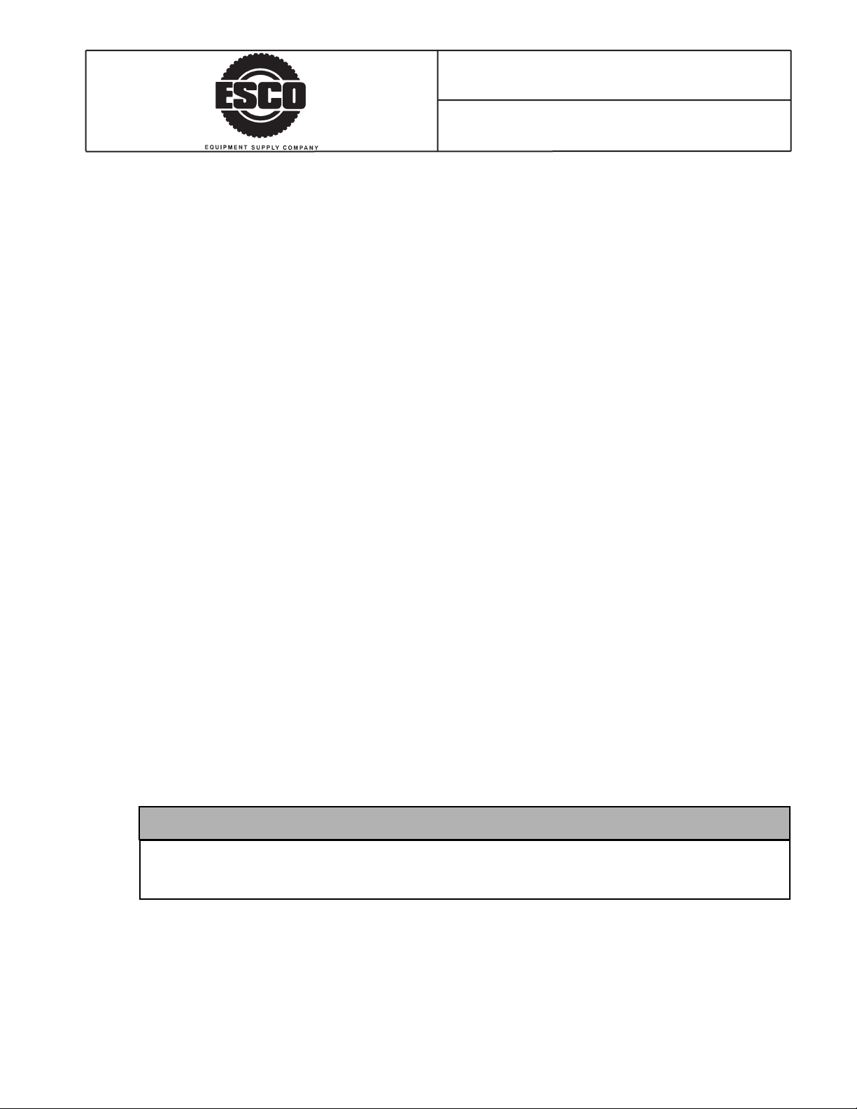
4 Visually inspect all tire and rim parts to make sure they are positioned properly.
Starting to Inflate the Tire
1. To comply with OSHA Regulation #29CFR1910.177, place the tire in a safety cage or other
restraining device, such as an ESCO Push Bar Model 90201, before inflating the tire. Use a clip-on
air chuck and hose that is long enough to allow you to stand outside the wheel trajectory. The air
line must be equipped with an in-line valve with pressure gauge or regulator that can be preset. Use
ESCO Truck Tire Inflator Model 15136.
ADANGER
Always use a safety cage or restraining device, such as an ESCO Push Bar Model 90201, when
inflating a tire. Not using a safety cage or restraining device can result in serious injury or death.
Always use a clip-on air chuck and a hose that is long enough to allow you to stand outside the
wheel trajectory. The air line must be equipped with an in-line valve with a pressure gauge and a
regulator that can be preset.
Never use starting fluid, ether, gasoline, or any other flammable material to lubricate, seal, or seat
the bead of a tubeless tire. Doing so can cause an explosion and serious injury or death.
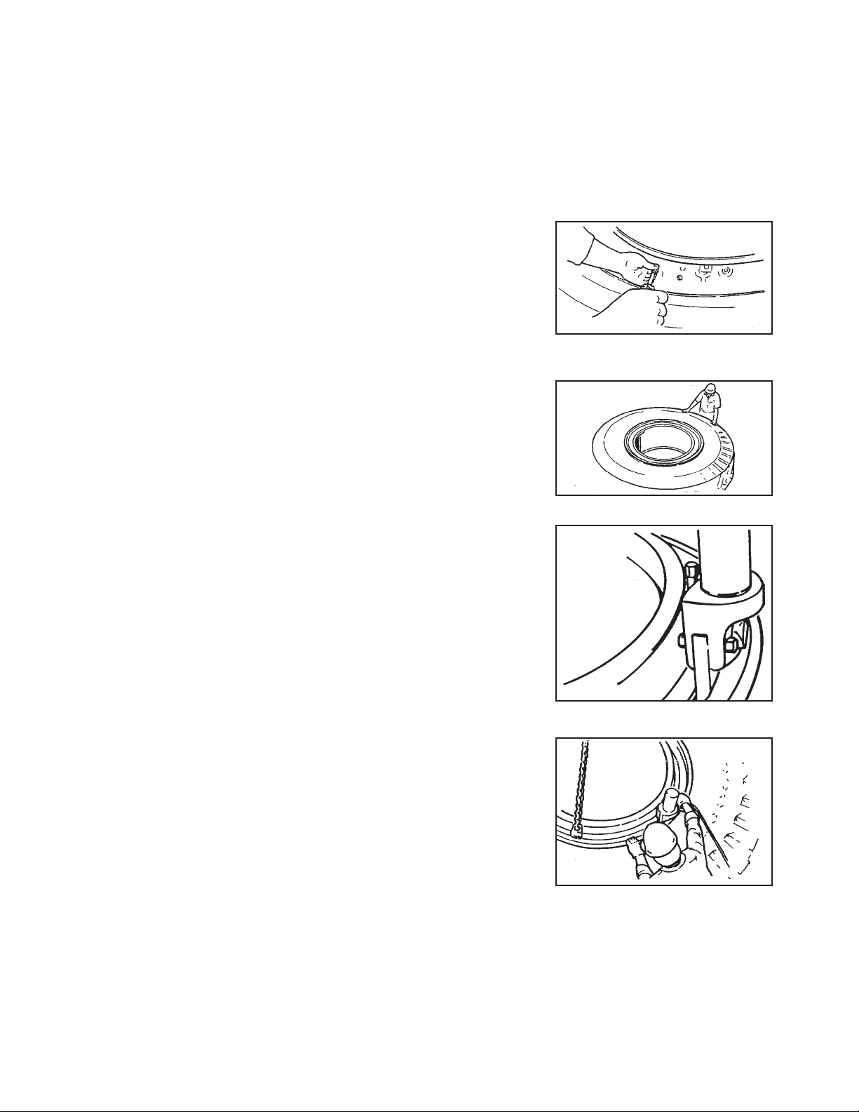
2. Inflate the tire to 5 psi [0,345 bar].
3. Check all tire and rim parts again for proper positioning. Make sure the o-ring does not slip out of
its groove.
4. If tire/rim parts are not seated properly, deflate the tire and correct the problem before proceeding.
AWARNING
Never hammer, strike, or pry an inflated or partly inflated tire/rim assembly. If you must seat a
part or correct a problem, always deflate the tire first.
ACAUTION
Do not use a steel hammer on rim or rim parts.This can damage the rim. If you must reposition
tire or rim parts, use a rubber, plastic, or brass-faced hammer.
If a tire/rim assembly does not slide over a cast spoke wheel, do not force the assembly by
hammering. Instead, deflate the tire and inspect for warped or incorrectly seated parts, such as
lock rings.
5. If tire and rim parts are seated properly, proceed to “Finishing the Tire Inflation” below.
Finishing the Tire Inflation
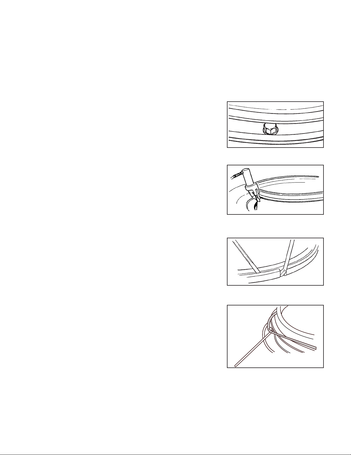
1. Inflate the tire to 20 psi [1,38 bar].
2. Check the tire bead for proper seating.
3. Continue inflating the tire to 40 psi [2,76 bar] If the tire bead is not fully seated, see the Warning
below. If the tire bead is fully seated, continue with Step 4 below.
AWARNING
Never inflate a tire beyond 40 psi [2,76 bar] to seat a tire bead. If the tire bead is not fully seated
at 40 psi: Stop! Deflate the tire and correct the problem.
- 5 -

4. Once you see that the tire bead is fully seated at 40 psi [2,76 bar], deflate the tire completely.
5. Reinflate the tire slowly to the manufacturer’s recommended pressure.
ADANGER
Inflate and load tires only to manufacturer’s specifications. Over-inflating and overloading tires
can result in serious injury or death.
Never run a vehicle with only one tire of a dual assembly. Doing so can result in a collapse of the
vehicle and lead to serious injury or death.
- 6 -
Table of contents
Popular Other manuals by other brands

SEVERIN
SEVERIN Freezer datasheet

Mira
Mira Leap Walk In installation guide

Compaq
Compaq 203039-B21 - Console Management Controller installation instructions

VST
VST GREEN MACHINE VST-GM-CS2-101 Installation, Operation, Maintenance, & Troubleshooting Manual

Oase
Oase ClearTronic 7 W operating instructions

RTS
RTS Fiber Optic Interface Back Card installation instructions