Esco TC-11 User manual

TC-11
MULTIFUNCTIONAL TIME
RELAY (TIMER) 1.0 version

1. SPECIFICATIONS.
2
Output: Relay: Maximum resistive
load (for example, heater): Maximum inductive
load (for example, engine):
30A 250V~
5
10 cycles 20A, 4500W 8A, 1500W, 2HP(2KM)
2. OUTPUT CARRYING CAPACITY
3. FRONT PANEL.
OUTPUT1
reset
START/PAUSE/STOP commands
OUTPUT 1 signalling: LIGHTS: output active
time setting signalling
time display
timing and time setting T1 signalling
time setting T1 and value increasing key
timing and time setting T2 signalling
time setting T2 and value increasing key
button releasing RESET command
and entry to the configuration menu
start
stop
Digital input:
230VAC ±15% or 12VAC/DC or 24VAC/DC, max 3VA
Operating conditions: -5...60°C; 0...85%RH (non-condensing)
Storage conditions: -40...85°C; 0...85%RH (non-condensing)
Power supply:
D1: triggering START, STOP, PAUSE commands
D2: triggering RESET command
Measuring time accuracy: ±0,1%
Display and time unit setting
method:
User-selectable:
minutes:seconds (resolution: 1 second)
hours:minutes (resolution 1 minute)
Work mode:
Time relay or time counter,
6 user-selectable operating modes with automatic or
manual reset function
Display: LED, 4 digits 11mm height with graphic icons
Protection class: IP65 / II
Time range: 1s...99h59min, configurable, two sub-ranges
Time counting : Onward (from zero to set time)
Reversing (from set time to zero)
Input signal: Potential free, by transmission closing impulse on
contacts 2-3(RESET)and 4-5(START,STOP,PAUSE),
minimum impulse time 100ms
Output: Relay, 20A 250VAC
Time settings: T1 or T1 and T2

3
4. TIMER HANDLING.
4.1. TIME SETTING T1.
Press button for
2 sec.
Diodes and lights
up and seconds rate
starts to blink.
Using or buttons
Set the seconds value
and confirm with key
Then the minutes value
starts to blink.
Information:
To improve quick increasing or decreasing the settings values hold the or button.
Remarks:
-Press button in any moment to cancel the setting. To improve quick increasing or
reset
start
stop
reset
start start
stop stop
reset
reset
start
stop
Using or set the
minutes value and
confirm with button.
Diodes go off.
start
stop
4.2. TIME SETTING T2 (only when the user chooses the operation mode with using
two times T1 and T2: parameter F17= 3, 4, 5, 6).
Hold button for 2
seconds. Using or button
Set the seconds value
and confirm with key.
Then the minutes rate
starts to flash.
Information:
To improve quick increasing or decreasing the settings values hold the or button.
Remarks:
- press button to cancel the setting
reset
start
stop
reset
start start
stop stop
reset
reset
start
stop
Using or button
Set the minutes value
and confirm with key.
Diodes goes off.
start
stop
Diodes and lights
up and seconds rate
starts to flash.

4
4.4. LIST OF PARAMETERS.
Enter the menu holding
Button for 5 sec. Until
the first parameter F10
displays.
4.3. PARAMETERS PROGRAMMING.
Confirm the new
parameter value and
return to the parameter
list with key.
Using:
or
Choose the parameter
you want to change and
enter with key.
If the access to the menu
is protected, command:
displays.
Using , and
buttons enter the
password and confirm
with key.
Using:
or
Set the desired
parameter value.
Finish programming
pressing button or
enter the ‘’End’’ command
and press key or wait
30 sec. without pressing
any button
Remarks:
- press button to cancel the parameter setting
reset reset
start
stop
reset
start
start
stop
stop
start
stop
reset
start
stop
start
stop
reset
start
stop
start
stop
reset
start
stop
reset
start
stop
reset
start
stop
reset
F81 -
10, 1
Memory of the calculated value after power loss
0 - NO; 1 - YES
F95 -
-
Reserved. -
Code: Units:
Default:Description:
F10 -
0
Unit and time range selection:
0=minutes/seconds, range: 00:01...99min:59s
1=hours/minutes, range: 00:01...99h:59min
F11 min:s/h:min
01:00Time setting T1 value.
Range:
0, 1
00:01...99:59
Group:
Operation parameters
F12 min:s/h:min
00:30Time setting T2 value. 00:01...99:59
-
1
F18 PAUSE function: 0=inactive, 1=active 0, 1
F50 0
Digital input work mode (see: 6.2)
F80 -
OFF
Password to access the configuration menu. OFF
– password protection inactive, F80 = 0000 – no password
0...7
0000...9999
F82
-
0
Functions of the buttons protection:
0=no protection, 1=RESET button inactive,
2=RESET and START/STOP button inactive,
3=time setting locked,
4=all buttons inactive.
F98 -
-
Reserved.
0...4
-
F99 Controller test.
Disconnect output device to make the test !
Otherwise the system can crash.
End Exit.
Others
-
F15 -
1
The direction of the display timing:
0=increasing (from zero to the setting)
1=decreasing (from the setting to zero). 0, 1
F17 -
1Timer work mode (see: point 5) 1...6
Seconds
30
Duration of the sound signalling
(buzzer) after countdown.
0=buzzer off. 0...9999
F83
-
0
0, 1
-
--
F90 -
-Software version. -

5. TIMER WORK MODE.
F17=1 Delayed switch off
Timer turns on Output1 for T1 time after the START
command. After that time, timer turns off Output1 and turns
on beeper. The beeper operates fot the time set in
F83 parameter. You can mute it with any button in any time.
Time T1
Output1
On
Off Time
Time
F83
Beeper
On
Off
START
Time
F17=2 Delayed switch on
Timer counts down T1 time after the START command.After
that time, timer turns on Output1 and beeper. Beeper
operates for the time set in F83 parameter. You can mute it
with any button in any time.
time T1
Output1
On
Off Time
Time
F83
Beeper
On
Off
START
Time
F17=3 Cyclic switch off
Timer turns on Output1 for T1 time after the START
command.after that time, timer turns off Output1for T2 time. .
Then it switches Output1 on for T1 time again. Cyclic
operation continues until the RESET command.
Time T1
Output1
On
Off Time
Beeper
On
Off
START
Time
Time T2 Time T1
F17=5 Delayed temporary switch on T1
Timer counts down T2 time after the START command.After
tha time, timer turns on Output1 for T1 time and then the
beeper. Beeper operates for the time set in F83 parameter.
You can mute it with any button in any time.
czas T1
Output1
On
Off Time
Beeper
On
Off
START
Time
czas T2
Time
F83
F17=6 Delayed temporary switch on T2
Timer counts down T1 time after the START command.After
tha time, timer turns on Output1 for T2 time and then the
beeper. Beeper operates for the time set in F83 parameter.
You can mute it with any button in any time.
Time T1
Output1
On
Off Time
Beeper
On
Off
START
Time
Time T2
Time
F83
F17=4 Cyclic switch on
Timer counts down T1 time after the START command.After
that time, timer turns of Output1 for T2 time. Then it turns off
Output1 for T1 time. Cyclic operation continues until the
RESET command.
Time T1
Output1
On
Off Time
Beeper
On
Off
START
Time T2 Time T1
Time
Timer operates in one of the following work modes. Depending on you needs, choose the
suitable function for your system.
Currently measured time T1 ( icon) or time T2 ( icon) is indicated on the display while
working . Time T2 is locked, when it is not in use (parameter F17=1,2). After lapse of set time,
Output1 is turned on or off, which is signalled by diode. The end of countdown is signalled by
message on the display and it can be also signalled by built-in beeper (F83 parameter).
5

START STOP START
6. START/STOP/PAUZA/RESET COMMANDS.
reset
start
start
start
stop
stop
stop
Timer can be controlled by buttons or and external signal applied to the D1 input.
6.1. BUTTONS CONTROL.
Commands can be activated by buttons on a front panel.
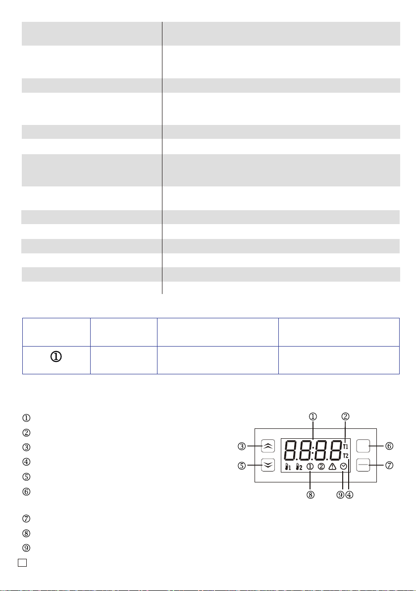
START
Press to start the countdown. Countdown passage of time is
indicated on the display, by or diode and by colon flashing
(flashes only when F10=1).
reset
start
stop
PAUZA/STOP
When PAUSE fucntion is active (F18=1). While counting down you
can stop it with key. While stoppage the display shows
message. Counting down can be resumed with button. When
the PAUSE fucntion is inactive (F18=0). Pressing button
finishes counting down and the displat shows message.
reset
start
stop
start
start
stop
stop
RESET
Press button to cancel the countdown.
reset
start
stop
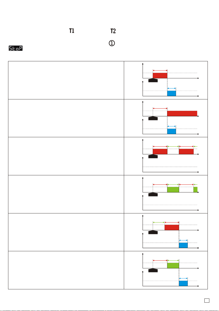
6.2. EXTERNAL ALARM CONTROL.
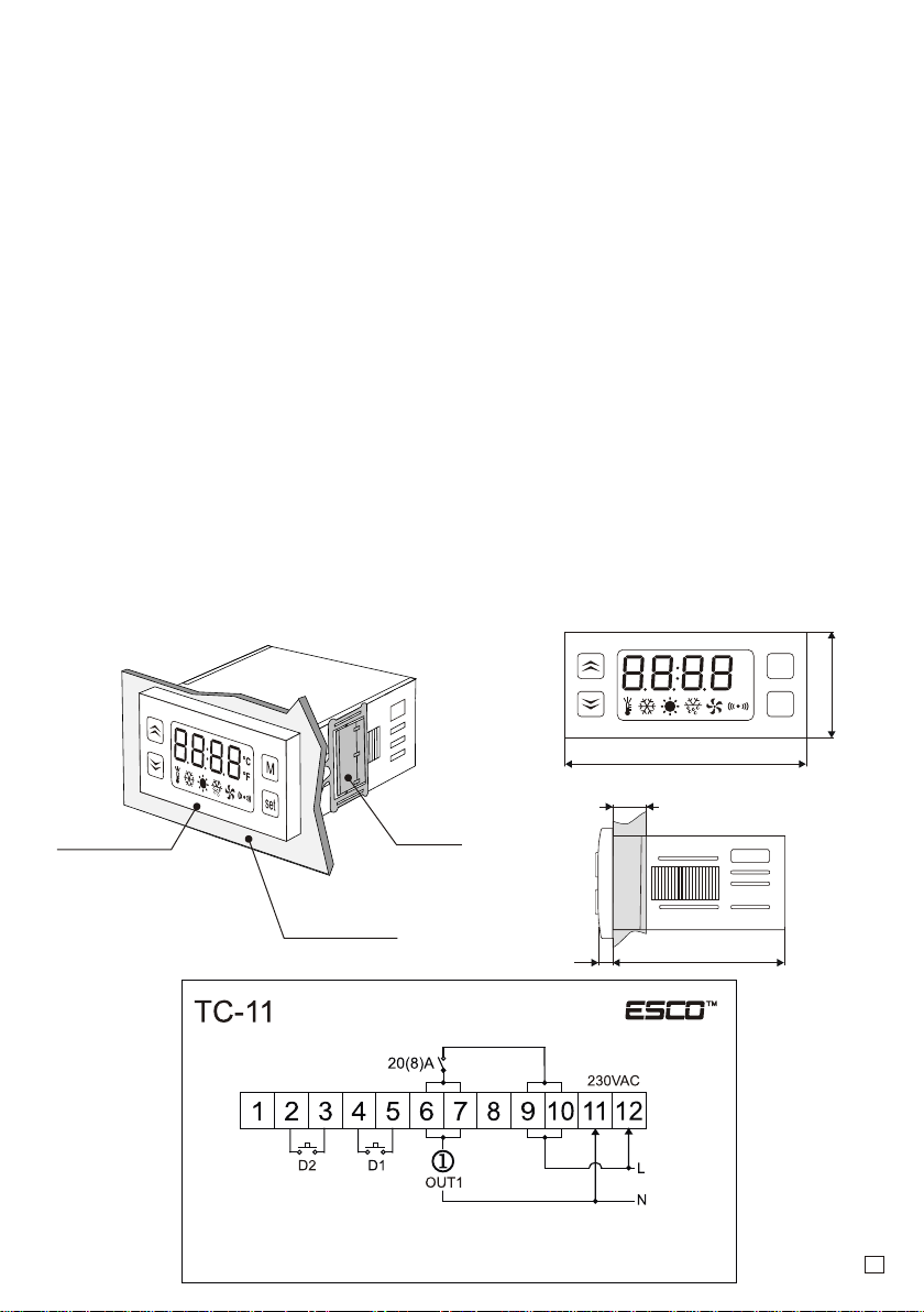
Commands can be also enabled by shorting circuit signal applied to D1 digital input. Connect
the circuit with shorting element to 4-5 contacts for example. With simple bipolar (bistable) or
bell pulse (monostable) switch and choose one of the following digital input work modes in F50
parameter. Shorting 4-5 contacts circuit the following commands will be triggered.
F50=1 START command only
(signal from bipolar or pulse switch).
Time
Input D1
Closed
Opened START Time
Time
count T1=8 0,1,2,3,4,5,6,7,T1=8
Time
Input D1
Closed
Opened Time
Time
count 0,1,2,3,4,5,6
F50=2 STOP command only
(signal from bipolar or pulse switch).
STOP
F50=3 START/STOP commands with PAUSE function
(signal from bipolar switch).
Time
Input D1
Closed
Opened START Time
Time
count 0,1,2,3,4
F50=4 START/STOP commands without PAUSE function
(signal from bipolar switch).
4,5,6,7,T1=8
STOP START
PAUZA
Time
Input D1
Closed
Opened START Time
Time
count 0,1,2,3,4 0,1,2,3,4,5,6,7,T1=8
STOP START
F50=5 START/STOP commands with PAUSE function
(signal from pulse switch).
Time
Input D1
Closed
Opened START Time
Time
count 0,1,2,3,4
F50=6 START/STOP commands without PAUSE function
(signal from pulse switch).
4,5,6,7,T1=8
STOP START
PAUZA
Time
Input D1
Closed
Opened czas
Time
count 0,1,2,3,4 0,1,2,3,4,5,6,7,T1=8
T1=8
T1=8 T1=8
T1=8 T1=8
START
0,1,2,3...
0,1... 0,1...
START
0,1...
START
0,1...
6

7
9. MOUNTING.
Controller should be placed in the panel in hole sized 71 x 29mm and fasten with mounting
terminals.
Mounting
terminals
Ip65
protection class
Panel surface
(maximum thickness
20mm)
°C
°F
76
35
M
set
72
max 20
4,5
8. INSTALLATION.
Be aware of the conditions where the controller operates. Install in a place, where there is not
too high temperature and humidity and no condensation. Should be ventilated in order to
remove the heat.
ATTENTION!
It is not allowed to work with electric cables when the device is powered. You should avoid
crossing wires by using short connections. We recommend securing the source of controller
power supply and temperature sensor input against electrical interference.
10. WIRING DIAGRAM.
Power supply
D1 - digital input START/STOP/PAUSE
D2 - digital input RESET
OUT1 - output 20A-AC1 (8A-AC3) 250V~
6.3. EXTERNAL ALARM CONTROL (RESET).
Reset command can be induced by a short-circuit signal applied to D2 digital input.
The 2-3 contacts must be connected to the shorting pulse circuit element including the bell
pulse switch (monostable). Short circuit of 2-3 contacts will induce RESET command , counting
will be cancelled and reset.
7. OPERATING AFTER POWER LOSS.
TC-11, depending on the version, is supplied with 230VAC or 12VAC/DC or 24VAC/DC.
A power shortage may occur during the operation of the device. The F81 parameter determines
the operation of the device after a power shortage.
If F81=0, when the power returns, the timer resets, resets the value and deactivates the control
output.
If F81=1, after the power returns, the timer will continue to count down and run the control
output.

M
set
Make sure that the electrical parameters of the device correspond to the parameters of the
controller(maximumvoltage,currentrating,power).
Diagramofconnectingthereceivingdevice:
11.CONNECTION OF RECEIVING DEVICES
12. FACTORY SETTINGS.
If you forgot you password to the configuration menu or the timer after a power failure or a short
circuit displays memory error you can restore default parameter settings:
Turn off the timer.Then
press both buttons
, at one time and
switch the power supply
on holding the buttons..
Command:
clear” displays.
Command disappears
after 5 seconds and four
horizontal pointers
display. Then release the
buttons and the controller
restores factory settings
and goes into normal
operation mode .
M
set
8
Timer meets the requirements for immunity to electromagnetic interference in an industrial
environment according to the following standards:
Electromagnetic compatibility (EMC):
–EN-61000 part 6-4 – requirements for emissivity in an industrial environment
–EN-61000 part 6-2 – requirements for immunity in an industrial environment
It also meets the safety requirements according to standard:
–EN-61000 part 1 – safety requirements for eletrical devices
Controller meets the requirements of EU directives No. 72/23/EEC; 93/68/EEC; 89/336EEC.
13. ADMiSSIONS.
20(8)A 250VAC Power
230VAC
Power supply
230VAC
Input D1
START/STOP
TC-11
712
6
Receiving device
NN
L
L
L
11109
N
54
Input D2
RESET
32
Table of contents
Other Esco Relay manuals