manuals.online logo
Brands
  1. Home
  2. •
  3. Brands
  4. •
  5. Leviton
  6. •
  7. Relay
  8. •
  9. Leviton WSP05-010 User manual

Leviton WSP05-010 User manual

3-Wire Relay Receiver
Cat. Nos. WSP05-010, WSP05-020, WSP05-080, WST05-010, WST05-020 & WST05-080
International versions available
INSTALLATION
PROGRAMMING:
The receiver must be powered when programming. After programming, settings are retained when power is disconnected. The
receiver sensitivity is reduced when in Learn Mode to prevent unintentionally associating unwanted transmitters with the receiver.
Transmitters should be within 15 feet (5 meters) of the receiver when programming. Program the receiver in any of the modes
below.
Rocker Mode (default): In Rocker Mode the receiver responds only on a transmitter press and not on the release. For example,
one side of the rocker on a wireless light switch will activate the relay (turn the light ON) when pressed and the opposite side of the
same rocker will deactivate the relay (turn the light OFF) when pressed.
Momentary Mode: In Momentary Mode, each end of the rocker on a wireless light switch acts as a separate button. Each end of
the rocker programs separately to 1 or more receivers. When a rocker is pressed the output on the receiver will activate (turning the
electrical load ON). When the rocker is released the output will deactivate (turning the electrical load OFF).
Toggle Mode: In Toggle Mode, each end of the rocker acts as a separate button. Each end of the rocker programs separately.
When the rocker is pressed the output of the receiver will always change state (if OFF, it will turn ON; if ON, it will turn OFF). Like
Rocker Mode, the output status only changes when a button is pressed and is ignored on the release.
Follow the instructions below for the desired programming mode:
Rocker Mode (default) Programming Instructions
1. Read all Rocker Mode programming steps before taking any action to program receiver in Rocker Mode.
2. Activate Rocker Learn Mode by pressing and holding the LRN button for 1 second (See Figure A). The electrical load
connected to the receiver will begin turning ON and OFF in a slow pattern.
3. When associating a wireless light switch with the receiver, press one end of a switch rocker (See Figure B). When associating
a transmitter other than a wireless light switch, press the LRN or TCH button on the transmitter (see appropriate transmitter
starter guide). The load will stay ON for about 3 seconds indicating that the receiver has stored the transmitter’s unique ID in its
memory.
4. NOTE: If only one transmitter is desired then skip Step 4 and exit Learn Mode by following Step 5. To associate a second
transmitter with this receiver, wait until toggling of the load resumes. Repeat the instructions in Steps 3 and 4 until the unique
IDs of all desired transmitters (up to 30) are stored in the memory of the receiver.
5. To complete programming, just wait; the receiver automatically exits Learn Mode after 30 seconds. Alternatively, press and hold
the LRN button for 2 seconds to exit Learn Mode.
Momentary Mode Programming Instructions
1. Read all Rocker Mode programming steps before taking any action to program receiver in Momentary Mode.
2. While the receiver is in Rocker Learn Mode, press and hold the LRN button for 3 seconds (See Figure A). The electrical load
connected to the receiver will begin turning ON and OFF in a fast pattern. The receiver is now in Momentary Learn Mode.
3. Follow steps 3-5 of "Rocker Mode Programming Instructions."
Toggle Mode Programming Instructions
1. Read all Rocker and Momentary Mode programming steps before taking any action to program receiver in Toggle Mode.
2. While the receiver is in Momentary Learn Mode, press and hold the LRN button for 3 seconds (See Figure A). The electrical
load connected to the receiver will continue turning ON and OFF in a fast pattern. The receiver is now in Toggle Learn Mode.
3. Follow steps 3-5 of "Rocker Mode Programming Instructions."
Selective Deleting: Follow the Program Mode steps above to delete a transmitter from a receiver’s memory. Upon pressing the
LRN button on a transmitter (See Rocker Mode Programming Instructions, Step 3) which has previously been associated with
the receiver, the electrical load connected to the receiver will stay OFF for 3 seconds indicating that the receiver has removed the
transmitter’s unique ID from its memory.
Clear All: If the CLR button is pressed and held for 2 seconds (See Figure C), the entire memory of the receiver will be deleted.
The receiver will instantly enter the default programming mode (Rocker Mode) indicated by the electrical load turning ON and OFF.
WARNINGS AND CAUTIONS:
• TO BE INSTALLED AND/OR USED IN ACCORDANCE WITH APPROPRIATE ELECTRICAL CODES AND REGULATIONS.
• IF YOU ARE NOT SURE ABOUT ANY PART OF THESE INSTRUCTIONS, CONSULT AN ELECTRICIAN.
• RELAY RECEIVERS ARE INTENDED ONLY FOR USE INDOORS, IN DRY LOCATIONS, AND WITH PERMANANTLY INSTALLED
FIXTURES.
• SUITABLE FOR USE ON A CIRCUIT CAPABLE OF DELIVERING NOT MORE THAN 15 RMS SYMMETRICAL AMPERES MAXIMUM.
• RELAY RECEIVERS SHOULD NOT BE INSTALLED IN A LOCATION WHERE THE UNIT WILL BE IN CLOSE PROXIMITY TO THE
LIGHT BULB(S) OR OTHER SOURCES OF HEAT, PARTICULARLY WITH HIGHER WATTAGE LOADS. INSTALLATION IN CLOSE
PROXIMITY TO LIGHT BULBS OR OTHER HEAT SOURCES MAY SUBJECT THE RECEIVER TO TEMPERATURES EXCEEDING
THE OPERATING TEMPERATURE RATING (SEE SPECIFICATIONS TABLE).
DESCRIPTION:
The 3-Wire Relay Receiver provides fast and simple installation of remote controls for lighting and other loads. The receiver responds to
radio signals from self-powered wireless light switches and other compatible transmitters. The receiver mounts in ceiling junction boxes,
wall switch boxes, and wiring cavities. The threaded version mounts through standard 1/2" knock-out holes (See Figure E).
COMPATIBLE DEVICES:
• Single Rocker Self-powered Wireless Light Switch
• Dual Rocker Self-powered Wireless Light Switch
• Handheld Self-powered Wireless Light Switch
• Key Card Access Switch
• SLT Wireless Sensor
• Self-powered Wireless Occupancy Sensor
• More transmitters available
TOOLS NEEDED FOR INSTALLATION:
• Non-conductive probe (pencil or ballpoint pen) • Electrical tape • Wire nuts • Screwdriver
TO INSTALL:
The 3-Wire Relay Receiver provides fast and simple installation of remote controls for lighting and other loads. The receiver responds to
radio signals from self-powered wireless light switches and other compatible transmitters. The receiver mounts in ceiling junction boxes,
wall switch boxes, and wiring cavities.
Single Pole or Multi-way Wireless Switch (1 or more wireless light switches)
1. Read the WARNINGS AND CAUTIONS section before beginning these installation options. Read all steps for this option before
taking any action to install receiver.
2. WARNING: To avoid risk of re, shock, or death, TURN OFF POWER at circuit breaker or fuse and verify that it is OFF before
installation begins. Make sure that it remains OFF until installation is complete. Please be aware that with some versions of the
product, it is possible to have multiple branch circuits feeding the Relay Receiver.
3. For in-wall installation, a wiring box must be used. For ceiling installation make wire connections inside a junction box. Ensure that
the temperature in the ceiling box will not exceed 50 degrees C (see specications). For best wireless signal performance
install receiver in plastic box away from oor and away from metal objects.
4. Connect wires as shown in Figure D. Twist wire nuts on clockwise making sure no bare wires show. Wrap connections with
electrical tape.
5. Restore power and follow programming instructions for appropriate programming mode (see “Programming” below). For this
installation, Rocker Mode (the default programming mode) is recommended.
6. Test receiver. (If receiver is not working, review wiring and programming instructions or see “Troubleshooting” in product manual.)
7. Stow all wires in wiring box. Finish any installation of xture or wall switch.
DI-000-WST05-00A
FCC COMPLIANCE STATEMENT: Contains FCC ID: SZV-TCM2XXC. Contains IC: 5713A-TCM2XXC
The enclosed device complies with Part 15 of the FCC Rules. Operation is subject to the following
two conditions: (i.) this device may not cause harmful interference and (ii.) this device must accept
any interference received, including interference that may cause undesired operation.
Leviton is a registered trademark of Leviton Mfg. Co. in the United States, Canada, Mexico, and
other countries. Other trademarks herein are the property of their respective owners.
ETL (US) - Conforms to UL STD 244A & UL 2043 Plenum rating. This device was tested according
to and was found to comply with UL 244A Solid State Controls for Appliances.
ETL (Canada) - Certied to CAN/CSA STD C22.2 No. 14. This device was tested according to and
was found to comply with CAN/CSA STD C22.2 No. 14.
Press Transmitter
Figure B
CLR
LRN
For indoor use only.
For permanently installed fixtures only.
WHT
RED=N.O.
BLU=N.C.
YEL=Com.
BLK
FCC ID: SZV-TCM2XXC
IC: 5713A-TCM2XXC
3155572
STD: UL 244A
This product complies with part 15 of
FCC rules. See product manual.
120VAC CLR
LRN
Figure C
Clear All
WSP05-0x0
BREAKER PANEL
NOTE: The wire colors will be different
for WSP05-080 and WSP05-020,
different voltages have different color wires.
HOT
NEUTRAL
GREEN OR BARE
WHITE
GROUND
BLACK
RED
N.O.
AC POWER
AC POWER
WHI TE
BLACK
GREEN OR BARE
AC POWER
WHITE
GROUND
FIXTURE
AC POWER
BLACK
BATTERY-FREE,
WIRELESS SWITCHES
WIRELESS
CONTROL
SIGNAL
UP TO
150 FT.
WSS0S-D0x WSS0S-D2x
Figure D
Single Pole or Multi-way Wireless Switch (1 or more wireless light switches)
Automatic ON / Automatic OFF. If the receiver learns a wireless motion sensor, the
load will turn OFF after no occupancy has been detected for 15 minutes. If learned
in the Rocker Mode, the output will be Manual ON / Automatic OFF. If learned in
Momentary Mode, the output will be Automatic ON / Automatic OFF.
ADDITIONAL PROGRAMMING OPTIONS
Inverted Output Mode: The receiver supports the Inverted Output Mode of operation.
In the default conguration, the N.O. relay contact is open (not connected) when not
active, and closed (connected) when active. When the outputs are in Inverted Output
Mode, the N.O. contact is closed when not active and open when active. Inverting the
outputs may be used to emulate a normally closed relay that opens when a switch is
activated.
One common use for this mode is for magnetic door release controls. The output is
ON and the door-hold electromagnet is active until a Momentary switch is activated,
deactivating the electromagnet and allowing the door to close. The magnet is
reactivated as soon as the switch is released.
Inverted Output Mode Programming Instructions
1. Turn the power to the receiver OFF.
2. Press and hold the CLR button for 5 seconds while turning on the power. The load
will blink twice to indicate activation of Inverted Output Mode.
To change back to normal operating mode, repeat Steps 1 and 2. The load will blink
once to indicate normal (non-Inverted) mode. The state of this mode is stored in
non-volatile memory and is maintained even if the power is removed.
CLR
LRN
For indoor use only.
For permanently installed fixtures only.
WHT
RED=N.O.
BLU=N.C.
YEL=Com.
BLK
FCC ID: SZV-TCM2XXC
IC: 5713A-TCM2XXC
3155572
STD: UL 244A
This product complies with part 15 of
FCC rules. See product manual.
120VAC CLR
LRN
Enter Learn Mode
Figure A
For Technical Assistance Call: 1-800-824-3005 (U.S.A. Only)
www.leviton.com
LIMITED 5 YEAR WARRANTY AND EXCLUSIONS
Leviton warrants to the original consumer purchaser and not for the benet of anyone else that this product at
the time of its sale by Leviton is free of defects in materials and workmanship under normal and proper use for
ve years from the purchase date. Leviton’s only obligation is to correct such defects by repair or replacement,
at its option, if within such ve year period the product is returned prepaid, with proof of purchase date, and a
description of the problem to Leviton Manufacturing Co., Inc., Att: Quality Assurance Department, 201
North Service Road, Melville, New York 11747. This warranty excludes and there is disclaimed liability for
labor for removal of this product or reinstallation. This warranty is void if this product is installed improperly or
in an improper environment, overloaded, misused, opened, abused, or altered in any manner, or is not used
under normal operating conditions or not in accordance with any labels or instructions. There are no other or
implied warranties of any kind, including merchantability and tness for a particular purpose, but if any
implied warranty is required by the applicable jurisdiction, the duration of any such implied warranty, including
merchantability and tness for a particular purpose, is limited to ve years. Leviton is not liable for incidental,
indirect, special, or consequential damages, including without limitation, damage to, or loss of use of,
any equipment, lost sales or prots or delay or failure to perform this warranty obligation. The remedies
provided herein are the exclusive remedies under this warranty, whether based on contract, tort or otherwise.
© 2010 Leviton Mfg Co., Inc. DI-000-WST05-00A
SPECIFICATIONS
WSP05-010
WST05-010
WSP05-080
WST05-080
WSP05-020
WST05-020
Range 50-150 feet (typical)
Frequency 315 MHz (868MHz for International)
Relay Output 120 VAC 240 VAC 277 VAC
Max
Loads/
Contact
Ratings
Tungsten / Incandescent 500 W 1000 W 1150 W
Fluorescent Ballast 3 A
General Duty 6 A
A300 Pilot Duty 120 VA 240 VA 277 VA
Power Supply 120 VAC
50/60 Hz
240 VAC
50/60 Hz
277 VAC
50/60 Hz
Output Channels 1 FORM A Relay
Memory Stores up to 30 switch IDs
Dimensions
2.11 x 1.73 x 1.09 inches (54 x 44 x 28 mm)
2.61 x 1.73 x 1.09 inches (66 x 44 x 28 mm)
Threaded mount version
Operating Temperature 14° to +122°F (-10° to +50°C)
Storage Temperature -4° to +176°F (-20° to +80°C)
Radio Certication FCC (United States): SZV-TCM2XXC
I.C. (Canada): 5713A-TCM2XXC
Safety Approval
ETL (U.S.): UL244A & UL 2043 Plenum rating
ETL (Canada): CSAc22.2#14-05
UL 2043 Plenum rating
Note: Electrical Specications apply to threaded mount and international versions.
Figure E
Wireless Relay mounting options
Outside junction box
Junction box
Threaded
Wireless
Relay
Inside junction box
Junction box
Wireless
Relay

This manual suits for next models

5

Other Leviton Relay manuals

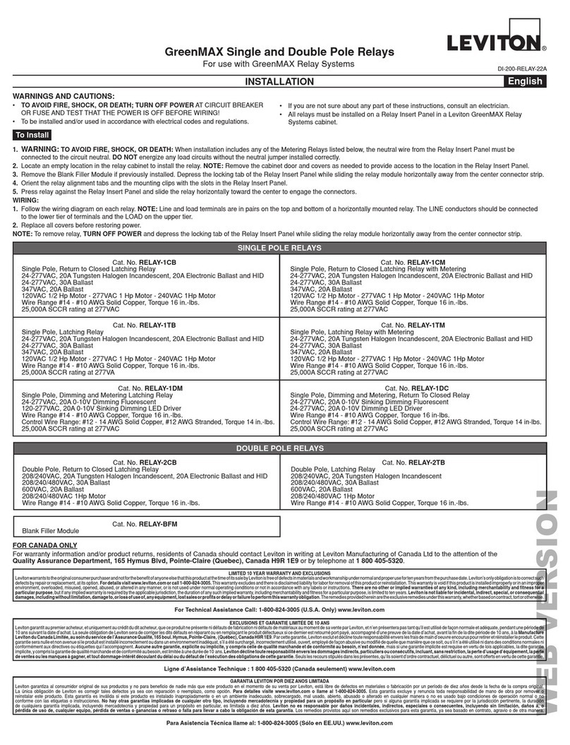
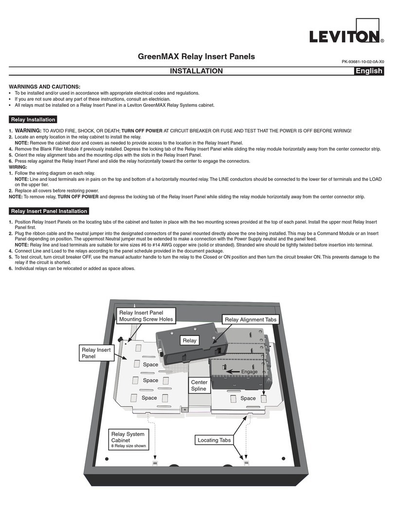
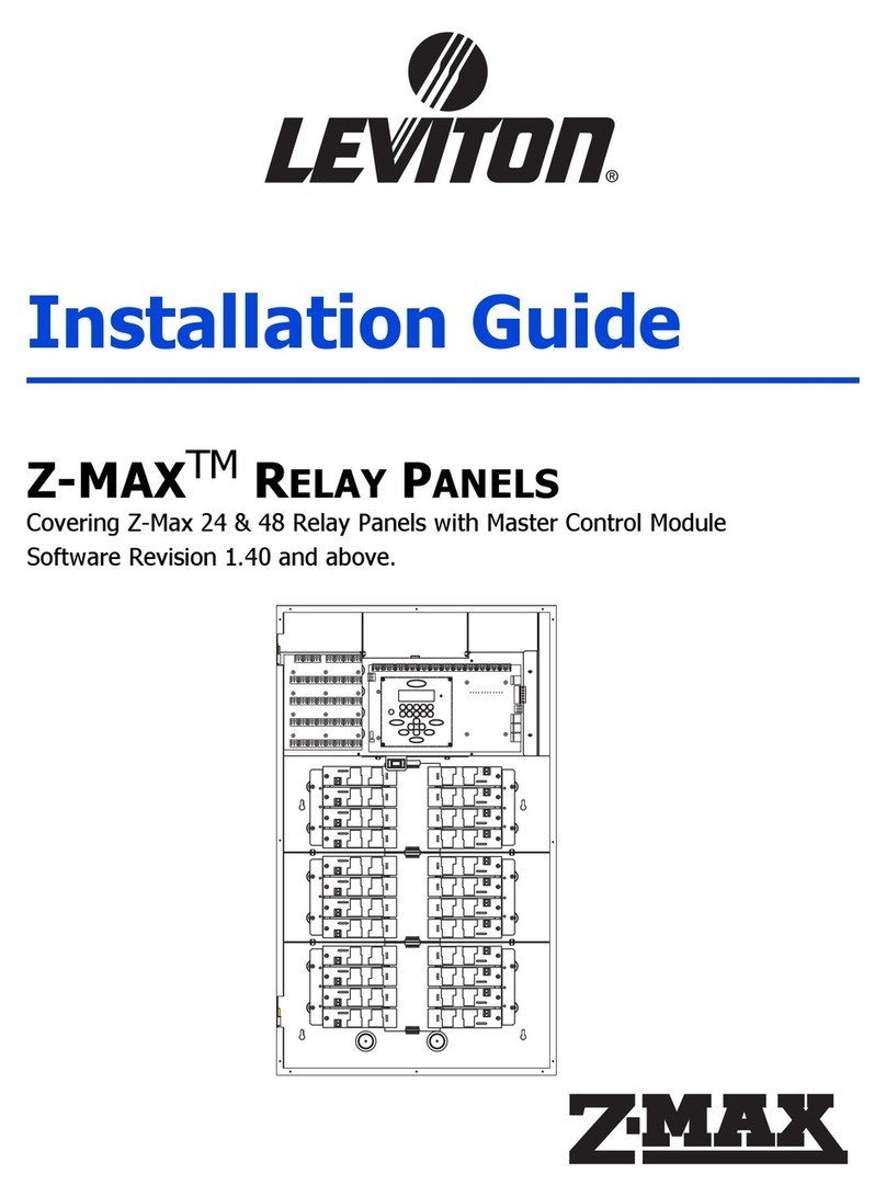
Leviton GreenMAX Relay System Cabinet User manual

Leviton

Leviton GreenMAX Relay System Cabinet User manual

Leviton GreenMAX RELAY-1TB User manual

Leviton

Leviton GreenMAX RELAY-1TB User manual

Leviton GreenMAX Series User manual

Leviton

Leviton GreenMAX Series User manual

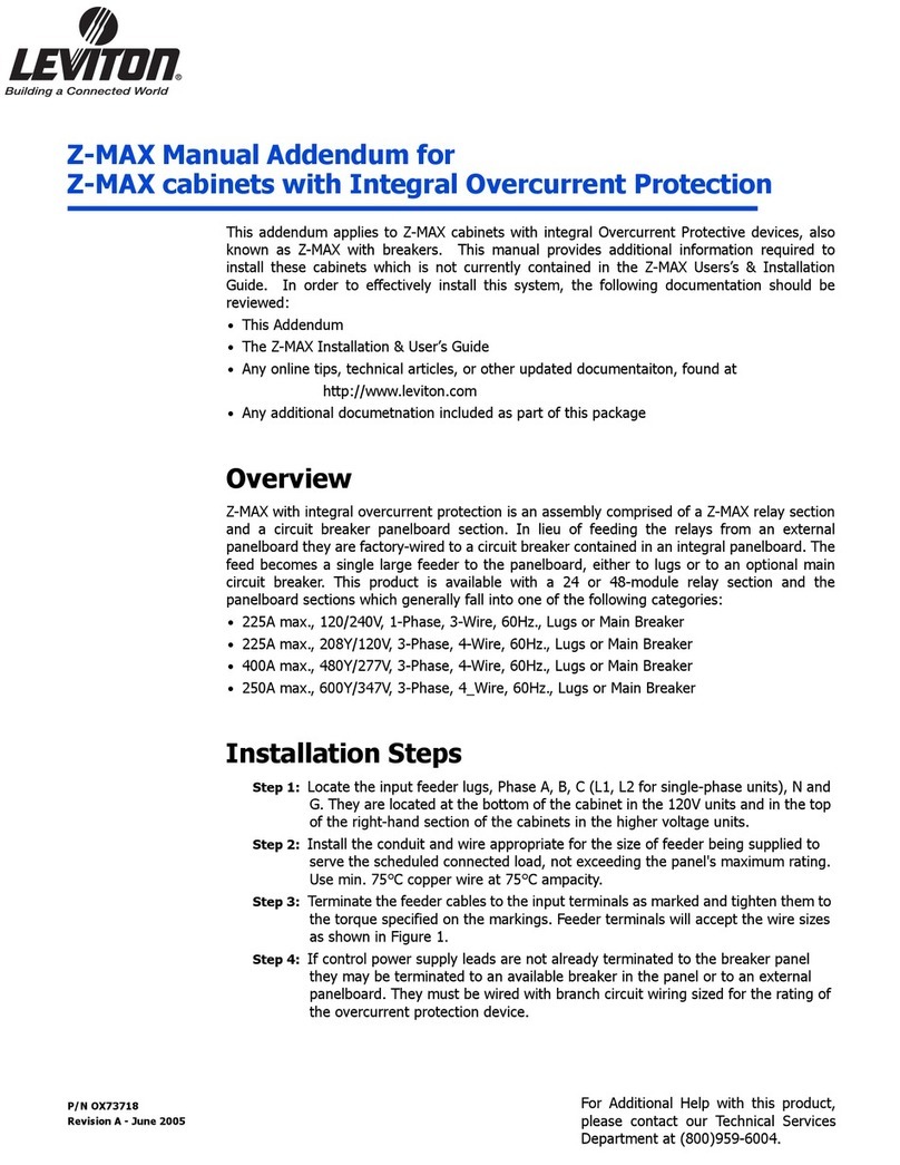
Leviton EZ-Max Plus Operating instructions

Leviton

Leviton EZ-Max Plus Operating instructions

Leviton GreenMAX R1616-1CB User manual

Leviton

Leviton GreenMAX R1616-1CB User manual

Leviton GreenMAX R16TC-100 User manual

Leviton

Leviton GreenMAX R16TC-100 User manual

Leviton Z-Max Remote Installation and operating instructions

Leviton

Leviton Z-Max Remote Installation and operating instructions

Leviton EnOcean WSPAS-LV4 User manual

Leviton

Leviton EnOcean WSPAS-LV4 User manual

Leviton EZ-MAX User manual

Leviton

Leviton EZ-MAX User manual

Leviton GreenMAX R16TC-100 User manual

Leviton

Leviton GreenMAX R16TC-100 User manual

Leviton 40A00-1 Mounting instructions

Leviton

Leviton 40A00-1 Mounting instructions

Leviton EZ-MAX H Series User manual

Leviton

Leviton EZ-MAX H Series User manual

Leviton EZ-Max Plus Operating instructions

Leviton

Leviton EZ-Max Plus Operating instructions

Leviton EZ-MAX Plus 8 User manual

Leviton

Leviton EZ-MAX Plus 8 User manual

Leviton EZ-MAX Plus 16 User manual

Leviton

Leviton EZ-MAX Plus 16 User manual

Leviton Z-MAX r24sd User manual

Leviton

Leviton Z-MAX r24sd User manual

Popular Relay manuals by other brands

Koncar konpro manual

Koncar

Koncar konpro manual

Woodward MFR 12 manual

Woodward

Woodward MFR 12 manual

MICROENER MC3V-X/10-4 Operation manual

MICROENER

MICROENER MC3V-X/10-4 Operation manual

Eaton ESR5-VE3-42 manual

Eaton

Eaton ESR5-VE3-42 manual

GE 750 instruction manual

GE

GE 750 instruction manual

Contrel ELRC-B user manual

Contrel

Contrel ELRC-B user manual

Eaton ETR4-70B-AB Instruction leaflet

Eaton

Eaton ETR4-70B-AB Instruction leaflet

Broyce Control P9600 Series quick start guide

Broyce Control

Broyce Control P9600 Series quick start guide

Eaton AGM2-10-PKZ0-PI Instruction leaflet

Eaton

Eaton AGM2-10-PKZ0-PI Instruction leaflet

Rockwell Automation Allen-Bradley Minotaur MSR138DP installation instructions

Rockwell Automation

Rockwell Automation Allen-Bradley Minotaur MSR138DP installation instructions

OEZ SE-BD-0040-MTV8 Instructions for use

OEZ

OEZ SE-BD-0040-MTV8 Instructions for use

Mikro NX231A user guide

Mikro

Mikro NX231A user guide

Pilz S1EN operating instructions

Pilz

Pilz S1EN operating instructions

Siemens Argus 7SR11 manual

Siemens

Siemens Argus 7SR11 manual

Allen-Bradley 140G Series quick start guide

Allen-Bradley

Allen-Bradley 140G Series quick start guide

Schweitzer Engineering Laboratories SEL-421-4 instruction manual

Schweitzer Engineering Laboratories

Schweitzer Engineering Laboratories SEL-421-4 instruction manual

ERICO DAR 275V installation instructions

ERICO

ERICO DAR 275V installation instructions

pizzato CS AR-01 Series operating instructions

pizzato

pizzato CS AR-01 Series operating instructions

manuals.online logo
manuals.online logoBrands
  • About & Mission
  • Contact us
  • Privacy Policy
  • Terms and Conditions

Copyright 2025 Manuals.Online. All Rights Reserved.