manuals.online logo
Brands
  1. Home
  2. •
  3. Brands
  4. •
  5. ESD SYSTEMS
  6. •
  7. Measuring Instrument
  8. •
  9. ESD SYSTEMS SPl-20686 Instruction Manual

ESD SYSTEMS SPl-20686 Instruction Manual

D SYSTE.c 
SPI Ground Gard 5 / 5.5
Operation, Installation, and Maintenance 

SPI
SPl-20686 94391
 















 












 






 

 




 







 

Capacitance Type Continuous Monitors















Item SPl-20686
 
 
 
 
 ® 
 
  
Item 94391
 
 
  
 
 
 
 ® 
 
 
TB-20686     
E_
Test Equipment Depot - 800.517.8431 - 99 Washington Street Melrose, MA 02176 - TestEquipmentDepot.com
Installation
1. SPI-20686 and 94391 Monitor Head:
The SPI-20686 and 94391 Monitors are designed to
maximize valuable work area and should be mounted at
eye level above the workstation, either on a post or shelf
support. A double-sided adhesive Velcro®attachment is
provided to hold the lightweight head in place.
2. GROUND CONNECTION:
The green wire extending from the monitor must be
attached to a facility ground.
Caution: The total amount of resistance through all
monitored parts should not exceed 10.0 megohms
total.
3. REMOTE OPERATOR MODULES:
The remote operator modules can be
mounted at the front of the work
surface, usually under the tabletop and
ush with the front edge. Two screws
for each unit are provided for mounting.
Connect each remote to the monitor unit using the
telephone cable with RJ11 connectors.
4. POWER UP TEST
After installing the Monitor , remote units, and making the
necessary connections without the wrist straps
connected, the unit should POWER UP with the wrist
strap LED’s OFF and the audible alarm SILENT. If you
have no response to power or a red LED, check AC
outlet for proper ground or refer to trouble shooting
section.
PARK SNAP
The audible alarm is designed to alert both operator and
supervisor. The Park Snap feature provides a means
for an operator to disconnect when normally leaving the
work area, without the audible alarm sounding, and it
provides a means of wrist cord storage. You may also
disconnect the coil cord by unplugging the banana plug
from the Remote Module. Both a 7mm and 4mm Park
Snap is provided on each module.
Remote Module Description
Inside both remote modules are infrared sensors that
react to the insertion of a wrist strap wire with a banana
plug. When the banana plug is inserted, the base unit is
activated for that remote module. The Monitor LED for
the left or right wrist strap will light showing the condition
of that strap. If correct, the LED should be GREEN.
Should the wrist strap fail, be worn incorrectly or
removed by the operator, the red indicator will ash,
calling attention to a problem. Should the ground
connection be lost, the red light and alarm will be
activated. The monitors are continuous and even a
momentary break will cause alarms. The remote
modules are set at the factory to allow for sensitivity of
the “average” human body model.
Calibration Procedure Using 94373
Tester
Testing the Remote Modules
Refer to Figure 2 to see the connection setup for the
94373 tester to the SPI-20686 and Figure 3 for the
94391 monitor. Make sure that the switch located on the
face of the tester is toggled to LEFT WS / RIGHT WS. If
connected properly, all three LEDs on the monitor should
be illuminated green.
TB-20686 Page 2 of 3 © 2016 DESCO INDUSTR ES INC.
Employee Owned
Figure 2. Connecting the SPI-20686 to the 94373 Tester.
SPI-20686
Remote Remote
94373
Figure 3. Connecting the 94391 to the 94373 Tester.
94391
Remote Remote
94373
To test the resistance of the left remote module, press
the black button labeled LEFT WS on the tester. If the
remote module is properly calibrated, the monitor’s
audible alarm will sound and the LEFT WRIST STRAP
LED will illuminate red. If the LED remains green, locate
the trim pot underneath the respective remote module.
Hold down the tester’s LEFT WS button and carefully
adjust the trim pot in a counter-clockwise direction until
the monitor indicates a FAIL condition. If properly
calibrated, the monitor should now indicate a FAIL
condition when the tester’s LEFT WS button is pressed.
To test the resistance of the right remote module, press
the black button labeled RIGHT WS on the tester. If
the remote module is properly calibrated, the monitor’s
audible alarm will sound and the RIGHT WRIST STRAP
LED will illuminate red. If the LED remains green, locate
the trim pot underneath the respective remote module.
Hold down the tester’s RIGHT WS button and carefully
adjust the trim pot in a counterclockwise direction until
the monitor indicates a FAIL condition. If properly cali-
brated, the monitor should now indicate a FAIL condition
when the tester’s RIGHT WS button is pressed.
Testing the Ground Monitor
Refer to Figure 2 to see the connection setup for the
94373 to the SPI-20686 and Figure 3 for the 94391.
Make sure that the switch located on the face of the
tester is toggled to LEFT WS / RIGHT WS. If connected
properly, all three LEDs on the SPI-20686 and 94391
should be illuminated green.
Disconnect the cords from the banana jacks on both
remote modules. Next, toggle the switch located on the
face of the tester to OPEN GND / HI RESIST. Press the
red button labeled OPEN GND on the tester, and if the
monitor is functioning properly, its audible alarm should
sound and the GROUND MONITOR LED should
illuminate red.
Press the red button labeled HI RESIST on the tester,
and the monitor’s audible alarm should sound and the
GROUND MONITOR LED should illuminate amber.
If any of these conditions are not met, contact the
manufacturer for repair.
Installation Adjustments
Should your system alarm without obvious cause, rst
troubleshoot and verify all connections. If all the
connectionsare correct, the base unit should be adjusted
to compensate for a di󰀨erent HBM (human body model).
We preset the units at the factory at 100pF and your
operator might be out of the tolerance range caused
either by body chemistry, bulk capacitance or impedance
di󰀨erences.
Follow these steps to adjust and personalize the base
unit:
Locate the small hole underneath the desired remote
module. Inside this hole is a trim pot device that is
adjustable by using a small at-head screwdriver.
With the system set up and operating, and the operator’s
wrist strap connected to the remote module:
Turn the trim pot clockwise until the LED illuminates
green. Disconnect the wrist cord from the band. An
audible alarm will sound and the LED will illuminate red.
If not, carefully turn the trim pot counter-clockwise until
the LED illuminates red. Reconnect the cord to the wrist
band. The alarm should cease and the LED should
illuminate green.
Ground Monitor
The SPI-20686 and 94391 include a ground monitoring
system that assures a positive ground connection for the
workstation. The resistance range is preset at the factory
to monitor that the connection to ground is within the
resistance range of 0.01 to 10 megohms. A visual and/or
audio alarm will verify pass or fault conditions.
CONDITION INDICATOR
PASS - Properly Grounded - LED Green
with Resistance less - No Audible Alarm
than 10 Meg.
HI RESIST - Grounded, but - LED Oscillate Green to
Resistance exceeds 10 Meg. Amber or Flashing Red
- Audible Alarm
FAIL - Loss of 1 or both - LED Flashing Red
redundant grounds, failure - Audible Alarm
of monitor, worktop, mat, etc.
Safety Issues
With regards to the safety issue, it is hard to conceive of
a safer situation than exists with the Ground Gard 5.5 as
designed.
1. The SPI-20686 and 94391 have a built-in safety
resistance of no less than 500k ohms at each remote
unit.
2. The transformer is wound on a split bobbin with 1500
volt insulation to assure no possible line leakage.
3. The circuits are double insulated by virtue of the
insulated plastic boxes.
4. 500k ohms internal to the SPI-20686 and 94391 and
one megohm in the wrist strap isolate the operator.
This may be varied by using a miltimeter set on ohms.
Connect the telephone type wire to the monitor and to
the remote unit. Place one end of the probe into the
banana receptacle at the remote, and the other to the
collar (power supply jack) located at the monitor.
TB-20686 Page 3 of 3 © 2016 DESCO INDUSTR ES INC.
Employee Owned
Limited Warranty, Warranty Exclusions, Limit of
Liability and RMA Request Instructions
See ESDSystem.com’s Terms and Conditions -
http://esdsystems.descoindustries.com/TermsAndConditions.aspx
Test Equipment Depot - 800.517.8431 - 99 Washington Street Melrose, MA 02176 - TestEquipmentDepot.com

This manual suits for next models

1

Other ESD SYSTEMS Measuring Instrument manuals

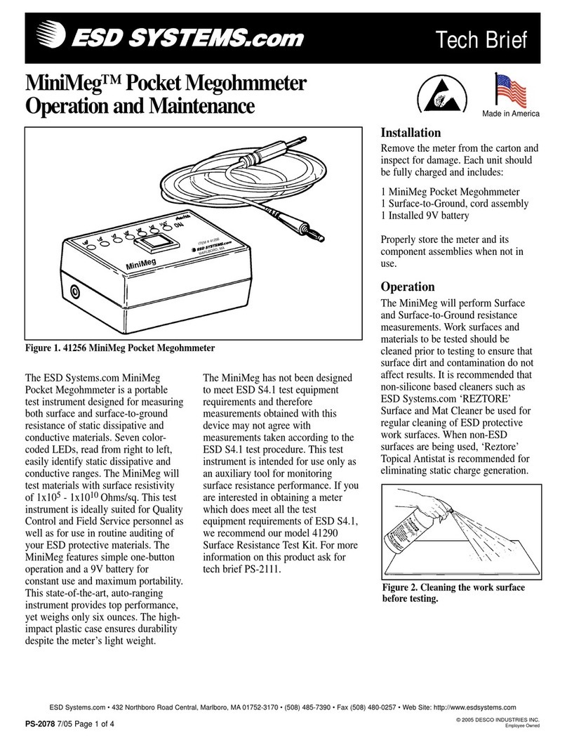
ESD SYSTEMS 41116 Instruction Manual

ESD SYSTEMS

ESD SYSTEMS 41116 Instruction Manual

ESD SYSTEMS 41273 Manual

ESD SYSTEMS

ESD SYSTEMS 41273 Manual

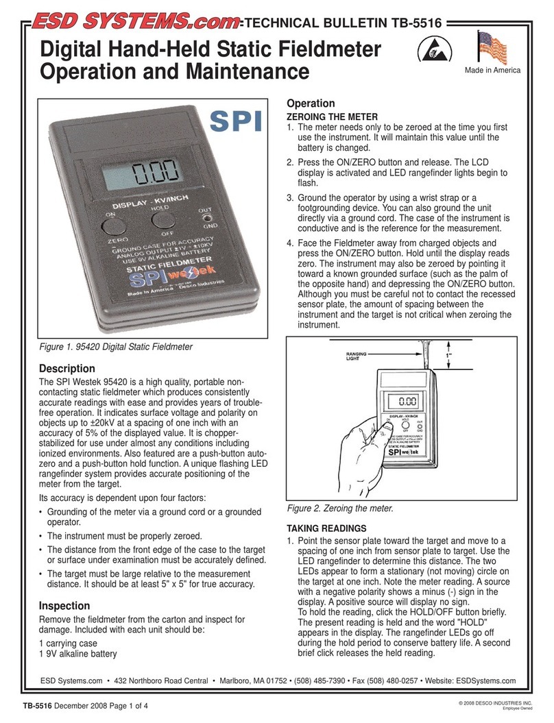
ESD SYSTEMS SPI Westek 95420 User manual

ESD SYSTEMS

ESD SYSTEMS SPI Westek 95420 User manual

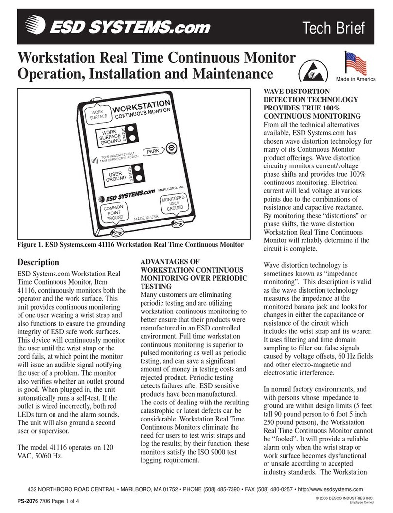
ESD SYSTEMS MiniMeg 41256 Installation guide

ESD SYSTEMS

ESD SYSTEMS MiniMeg 41256 Installation guide

Popular Measuring Instrument manuals by other brands

CohuHD Costar 3212-2000 quick start guide

CohuHD Costar

CohuHD Costar 3212-2000 quick start guide

KERN DLB 160-3A operating instructions

KERN

KERN DLB 160-3A operating instructions

Teledyne T360 Operation manual

Teledyne

Teledyne T360 Operation manual

DEGREE CONTROLS Cambridge Accusense ATM2400 user manual

DEGREE CONTROLS

DEGREE CONTROLS Cambridge Accusense ATM2400 user manual

ABB 4670 Series user guide

ABB

ABB 4670 Series user guide

Hanna Instruments PCA 310 instruction manual

Hanna Instruments

Hanna Instruments PCA 310 instruction manual

Martel Beta PTC8001 user manual

Martel

Martel Beta PTC8001 user manual

Micro Motion CDM100P installation manual

Micro Motion

Micro Motion CDM100P installation manual

GE PanaFlow Z1G quick start guide

GE

GE PanaFlow Z1G quick start guide

HEDÜ A412 manual

HEDÜ

HEDÜ A412 manual

Kistler 2519A Series instruction manual

Kistler

Kistler 2519A Series instruction manual

Georg Fischer Piping Systems MSA 340 instruction manual

Georg Fischer Piping Systems

Georg Fischer Piping Systems MSA 340 instruction manual

V-TEK PC-250+ quick start guide

V-TEK

V-TEK PC-250+ quick start guide

WiT E100F user manual

WiT

WiT E100F user manual

Sekonic FLASH MASTER L-358 quick guide

Sekonic

Sekonic FLASH MASTER L-358 quick guide

PCE Instruments D33 N user manual

PCE Instruments

PCE Instruments D33 N user manual

Kaiweets KC601 user manual

Kaiweets

Kaiweets KC601 user manual

Turner Designs C3 manual

Turner Designs

Turner Designs C3 manual

manuals.online logo
manuals.online logoBrands
  • About & Mission
  • Contact us
  • Privacy Policy
  • Terms and Conditions

Copyright 2025 Manuals.Online. All Rights Reserved.