manuals.online logo
Brands
  1. Home
  2. •
  3. Brands
  4. •
  5. ESD SYSTEMS
  6. •
  7. Measuring Instrument
  8. •
  9. ESD SYSTEMS 41273 Manual

ESD SYSTEMS 41273 Manual

LCD
Gain Pot
Zero Pot Linearity Pot
BATTERY
R11 R10 R9
Fig. 1. Front view with cover removed.
CCAALLIIBBRRAATTIIOONN
PPRROOCCEEDDUURREE
Item #41273 LCD Megohmmeter
This procedure must be followed exactly as
outlined in order to achieve accurate
readings from the meter. Start by installing a
fresh battery to ensure the meter’s power
supply has the correct operating voltages it
needs to give accurate results. The room in
which this calibration takes place should be
about 70°F and the humidity should not be
above 40% RH.
In order to proceed you will need to collect a few
1% precision resistors of the following values: 1
Meg Ohm, 22 Kilo Ohm, and a 1 Kilo Ohm
resistor. Each of the three resistors must be at
least 1% tolerance or better and 50ppm or
better. In addition you will need a pair of external
probe leads to connect the calibration resistors
to the meter. These should take the form of two
short lengths of wire, (about 6" @ 24 AWG) with
the proper size mono, male plug soldered on
one end and an alligator clip on the other end.
Begin by disassembling the meter case. Do not
remove the front label if there is one. Open
the meter by disassembling the two case
halves. Removing the front label will destroy
the meter.
To disassemble the meter, begin by removing
the three small threaded input jack retaining
rings on the front of the meter. Next turn the
meter over and remove the four screws. (One in
each corner of the meter.) Carefully turn the
meter back over keeping the two case halves
together. Next carefully lift the meter case front
off and set it on edge to the left side of the
meter. You will see two wires attached to the
front power switch. Be careful not to break
these wires or the meter will cease to
function.
Looking down onto the circuit board you will see
the three small, blue calibration adjustment
controls in the lower right corner of the board.
From left to right these controls are as follows.
The first one on the left is R11 or the Zero adjust-
ment. The second one to the right or the middle
one is R10 or the Gain adjustment. The last one
on the right is R9 or the Linearity control.
The following procedure must be followed
exactly as outlined or the calibration will not
be correct which will result in inaccurate
readings. These controls are very sensitive. A
small change can cause a large difference in
the reading so be careful and patient. Move
the controls very slowly and only a very
small amount at a time. After each change in
control settings, release the power button
and press and hold it again to ensure that the
meter is reading the change you just made.
Insert the probe leads that you are using into the
two probe jacks located in the lower left and
lower right corners of the board. Attach the 1
Meg Ohm resistor to the clip leads and be sure
that the ends of the leads that are attached to
the resistor don’t touch anything else
including the table that you are working on.
It is important for you to understand that all
of the calibration controls are interrelated.
That is, if you make a change to one control, the
other two may very well be out of calibration.
You must do a sort of balancing act between
the three controls in order to arrive at a
calibrated meter. Do the first one first, then the
second, and then the third. Then go back and
check them again. When you are getting close
you might notice that changing R11 affects the
reading of R9. You have to set R11 and recheck
R10 and R9. If you change R10 you need to
check R11 and R9. If you change R9 you need
to recheck R11 and R10 and so on.
Carefully push the red power button on the face
of the meter and hold it in while the meter makes
its reading. The meter should read close to
1.0 E 6. If the reading is too high, rotate R11 (the
one on the left) counterclockwise just a little
while pressing the red power button. If the
reading is too low, then rotate R11 clockwise
just a little while holding in the red power button.
As with each slight change you make with all
the controls, you must release the power
button and re-press and hold it to ensure that
the change you made is read by the meter.
Continue this process until the reading is 1.0 E 6.
Once the reading is 1.0 E 6 then proceed to the
next step.
Remove the 1 Meg Ohm resistor and replace it
with the 22 Kilo Ohm resistor making sure that
the resistor leads and the probe leads don’t
touch anything else. Press and hold the red
power button on the front of the meter and
observe the reading. The meter should read 2.2
E 4. If the reading is too high then carefully and
slightly rotate the R10 control counterclockwise
and re-test the change. If the reading was too
low then rotate R10 clockwise just a little and re-
test the change you made. After adjusting R10
the meter should read 2.2 E 4. Proceed to the
next step.
Remove the 22 Kilo Ohm resistor and replace it
with a 1 Kilo Ohm resistor. Press and hold the
red power switch. The meter should read
1.0 E 3. As with the other two adjustments, if the
reading is too high then rotate R9 counter-
clockwise and re-test. If the reading is too low
then rotate R9 clockwise a bit and re-test. When
the meter reads 1.0 E 3 then proceed to the next
step.
After the initial adjustments of the three controls
for the three calibration resistors you must now
go back and re-check all of the settings. The
reason for this is due to the fact that all three
controls are interrelated and must be adjusted
and calibrated together. To achieve this you must
start with R11. Re-adjust and re-test R11 with the
1 Meg Ohm resistor and then check, re-adjust
and re-test R9 and R10 with their respective
calibration resistors. Now start with R10 (22 Kilo
Ohms) and re-check and re-adjust R11 and R9.
Finally start with R9 (1 Kilo Ohms) and re-check
and re-adjust R11 and R10.
Once you have done this process a few times
all the readings should be exactly as
described. If one or more of the calibration
steps don’t result in an accurate reading then
something may be wrong with the meter. If
this occurs then you must send the meter
back to the factory for repair or replacement.
This instrument contains no end user
serviceable components. This meter utilizes
proprietary software that is copyright
protected. Any attempt to repair this
instrument by unqualified persons may result
in damage to its static sensitive components
and or the software program which would
void any warranty.

Other ESD SYSTEMS Measuring Instrument manuals

ESD SYSTEMS SPl-20686 Instruction Manual

ESD SYSTEMS

ESD SYSTEMS SPl-20686 Instruction Manual

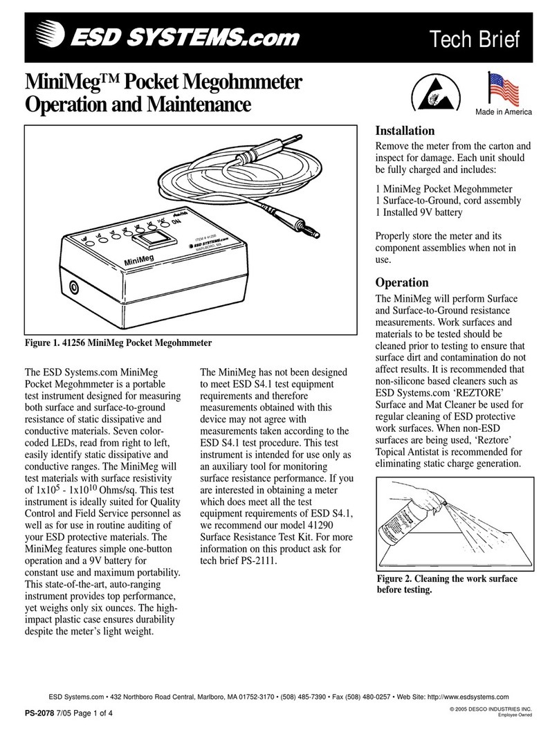
ESD SYSTEMS MiniMeg 41256 Installation guide

ESD SYSTEMS

ESD SYSTEMS MiniMeg 41256 Installation guide

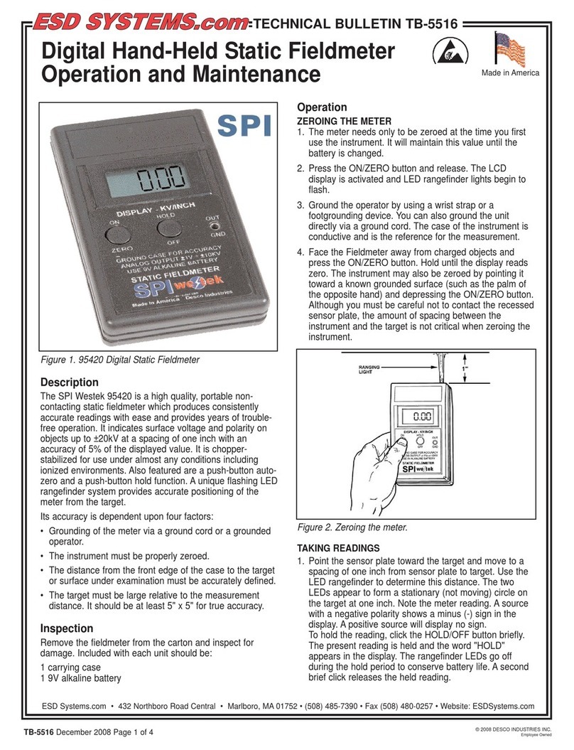
ESD SYSTEMS SPI Westek 95420 User manual

ESD SYSTEMS

ESD SYSTEMS SPI Westek 95420 User manual

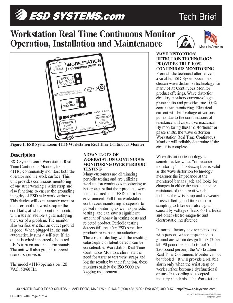
ESD SYSTEMS 41116 Instruction Manual

ESD SYSTEMS

ESD SYSTEMS 41116 Instruction Manual

Popular Measuring Instrument manuals by other brands

MW TOOLS OPDMP manual

MW TOOLS

MW TOOLS OPDMP manual

Circutor DCP-96 Vac instruction manual

Circutor

Circutor DCP-96 Vac instruction manual

Klein Tools NCVT-1 owner's manual

Klein Tools

Klein Tools NCVT-1 owner's manual

KROHNE OPTICHECK quick start

KROHNE

KROHNE OPTICHECK quick start

Rice Lake CLS-M iQube2 Upgrade Installation

Rice Lake

Rice Lake CLS-M iQube2 Upgrade Installation

FMS RMGZ200 installation manual

FMS

FMS RMGZ200 installation manual

Njoy DDSU666 user manual

Njoy

Njoy DDSU666 user manual

Elvaco CMi6140 quick start guide

Elvaco

Elvaco CMi6140 quick start guide

Ashcroft F5509 Installation and maintenance instruction manual

Ashcroft

Ashcroft F5509 Installation and maintenance instruction manual

HP 400D Operating and service manual

HP

HP 400D Operating and service manual

Morris Products 57085 manual

Morris Products

Morris Products 57085 manual

Ankom ANKOM200 FIBER ANALYZER Operator's manual

Ankom

Ankom ANKOM200 FIBER ANALYZER Operator's manual

LION SD-400 User handbook

LION

LION SD-400 User handbook

NeurOptics NPi-300 quick start guide

NeurOptics

NeurOptics NPi-300 quick start guide

a-eberle PQ-Box 150 operating manual

a-eberle

a-eberle PQ-Box 150 operating manual

MULTISPAN AVH-14 manual

MULTISPAN

MULTISPAN AVH-14 manual

sebaKMT Hydrolux HLE 500 operating instructions

sebaKMT

sebaKMT Hydrolux HLE 500 operating instructions

M&C SP180-H instruction manual

M&C

M&C SP180-H instruction manual

manuals.online logo
manuals.online logoBrands
  • About & Mission
  • Contact us
  • Privacy Policy
  • Terms and Conditions

Copyright 2025 Manuals.Online. All Rights Reserved.