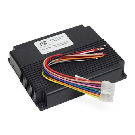
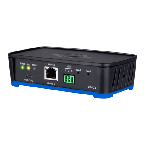
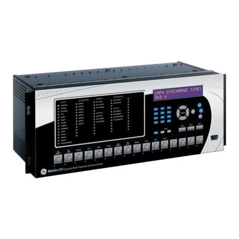
esera automation 1-Wire Controller 1 Owner's manual

All rights reserved. Reproduction as well as electronic duplication of this guide, complete or in part, requires the written consent of ESERA-
Automation or E-Service GmbH. Errors and technical modification subject to change. © ESERA-Automation, E-Service GmbH 2019
www.esera.de Programming Manual Controller-Gateway-Station V1.0 R1.1 Page 1 of 77
Programming Manual
1-Wire Gateway
1-Wire Controller
ESERA-Station
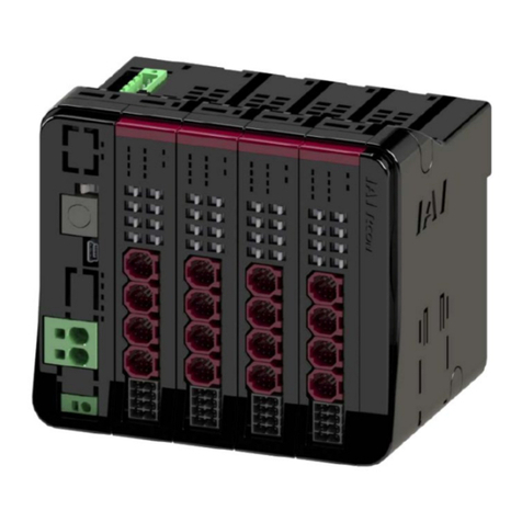
1-Wire Controller 1
1-Wire Controller 2 / 1-Wire Controller ECO 200
1-Wire Gateway 10
1-Wire Gateway 11
1-Wire Gateway 20
ESERA-Station 200
As of firmware V1.19_11

All rights reserved. Reproduction as well as electronic duplication of this guide, complete or in part, requires the written consent of ESERA-
Automation or E-Service GmbH. Errors and technical modification subject to change. © ESERA-Automation, E-Service GmbH 2019
www.esera.de Programming Manual Controller-Gateway-Station V1.0 R1.1 Page 2 of 77
1. ESERA Concept of Automation
1.1. 1-Wire Controller and 1-Wire Gateway
Sensors and actuators of the 1-Wire bus system are automatically detected, integrated and queried at very high
speed via the 1-Wire Controller / 1-Wire Gateway. The sensor and actuator data are transmitted to your controller
via Ethernet interface, via ASCII (1-Wire Controller) or via ASCII and Modbus protocol. The 1-Wire Controller and
1-Wire Gateway devices are compatible with all controllers within the Smart Home and Smart Automation area.
The 1-Wire controllers are widely used in private and semi-professional environments. Due to the Modbus
RTU and Modbus TCP interface, the 1-Wire Gateway devices are preferred in the demanding Smart Home
and professional automation area.
Core functions of the 1-Wire Controller / 1-Wire Gateway concept
•Independent recognition and management of sensors and actuators
•Fast cyclic data-retrieval of sensors and actuators
•Plausibility check of sensor data
•Data conversion for standard sensors and ESERA-Automation sensors as well as actuators through
integrated formula collection
•Data output in ASCII text and Modbus protocol (1-Wire Gateway only)
•Cyclic life signs (heartbeat) among controller / central control unit and 1-Wire Controller / 1-Wire
Gateway

All rights reserved. Reproduction as well as electronic duplication of this guide, complete or in part, requires the written consent of ESERA-
Automation or E-Service GmbH. Errors and technical modification subject to change. © ESERA-Automation, E-Service GmbH 2019
www.esera.de Programming Manual Controller-Gateway-Station V1.0 R1.1 Page 3 of 77
1.2. ESERA Station-200 Central Control Unit
Based on the know-how of the 1-Wire Gateway series, the ESERA Station-200 central control unit was developed.
Sensors and actuators of the 1-Wire bus system are automatically detected, integrated and interrogated at very
high speed via the integrated 1-Wire gateway. The data of the sensors and actuators are transmitted via an internal
serial interface as ASCII or Modbus protocol to the very powerful Quad Code Embedded Computer of the ESERA
Station.
Depending on the application software, the ESERA Station-200 is ideal for Smart Automation with Codesys 3.x,
IoT (Internet of Things) automation tasks or Smart Home applications.
A controller for many applications, in the commercial environment as well as in personal environment. It
offers many possibilities and a software-open automation platform.

All rights reserved. Reproduction as well as electronic duplication of this guide, complete or in part, requires the written consent of ESERA-
Automation or E-Service GmbH. Errors and technical modification subject to change. © ESERA-Automation, E-Service GmbH 2019
www.esera.de Programming Manual Controller-Gateway-Station V1.0 R1.1 Page 4 of 77
ESERA Station-200 is a combination of 1-Wire Gateway and embedded computer
•The 1-Wire Gateway System is based on a standardized bus system that has been successfully used
in industrial environments for many years.
•Open bus-system, compatible with sensors and actuators of third-party manufacturers
•Data preparation and output in a format readable by many controllers (ASCII characters) or Modbus*
protocol
Core functions of the 1-Wire Controller / 1-Wire Gateway concept
•Independent recognition and management of sensors and actuators
•Fast cyclic data-retrieval of sensors and actuators
•Plausibility check of sensor data
•Data conversion for standard sensors and ESERA-Automation sensors as well as actuators through
integrated formula collection
•Data output in ASCII text and Modbus protocol (1-Wire Gateway only)
•Cyclic life signs (heartbeat) among controller / central control unit and 1-Wire Controller / 1-Wire
Gateway
* 1-Wire Gateway devices only

All rights reserved. Reproduction as well as electronic duplication of this guide, complete or in part, requires the written consent of ESERA-
Automation or E-Service GmbH. Errors and technical modification subject to change. © ESERA-Automation, E-Service GmbH 2019
www.esera.de Programming Manual Controller-Gateway-Station V1.0 R1.1 Page 5 of 77
2. Table of content
1. ESERA CONCEPT OF AUTOMATION.....................................................................................................2
1.1. 1-WIRE CONTROLLER AND 1-WIRE GATEWAY................................................................................................2
1.2. ESERA STATION-200 CENTRAL CONTROL UNIT............................................................................................3
2. TABLE OF CONTENT...............................................................................................................................5
3. PRODUCT OVERVIEW.............................................................................................................................8
3.1. 1-WIRE CONTROLLER 1................................................................................................................................8
3.2. 1-WIRE CONTROLLER 2................................................................................................................................8
3.3. 1-WIRE GATEWAY 10 MODBUS RTU.............................................................................................................8
3.4. 1-WIRE GATEWAY 11 MODBUS TCP.............................................................................................................8
3.5. 1-WIRE GATEWAY 20 MODBUS TCP.............................................................................................................8
4. INTRODUCTION........................................................................................................................................9
4.1. INTEGRATION OF NEW 1-WIRE DEVICES .........................................................................................................9
4.2. CYCLIC DATA OUTPUT AND FORMATTING ........................................................................................................9
4.3. NUMBER OF 1-WIRE DEVICES AND TYPES.......................................................................................................9
4.4. IBUTTON ACCESS KEYS OR DS2401 SERIAL NUMBERS....................................................................................9
4.5. 1-WIRE OPERATING MODE.............................................................................................................................9
4.6. POWER SUPPLY 1-WIRE NETWORK................................................................................................................9
4.7. DATA FORMATTING .....................................................................................................................................10
4.8. POWER SUPPLY 1-WIRE CONTROLLER /1-WIRE GATEWAY...........................................................................10
5. MODBUS COMMUNICATION 1-WIRE GATEWAY................................................................................11
5.1. MODBUS TEST SOFTWARE...........................................................................................................................11
5.2. INTERFACE CONFIGURATION MODBUS TCP..................................................................................................12
5.3. MODBUS AND ASCII DATA OUTPUT..............................................................................................................13
5.4. MODBUS FUNCTION CODES .........................................................................................................................13
5.5. MODBUS READING ADDRESSES,1-WIRE GATEWAY 10, 11 AND 20, SYSTEM VARIABLES .................................15
5.6. MODBUS READING ADDRESSES 1-WIRE SENSORS........................................................................................16
5.7. MODBUS READING ADDRESSES 1-WIRE TEMPERATURE SENSORS.................................................................19
5.8. MODBUS READING ADDRESSES 1-WIRE ACTUATORS....................................................................................21
5.9. MODBUS WRITE ADDRESSES .......................................................................................................................23
5.10. MODBUS WRITE ADDRESSES 1-WIRE SENSORS ............................................................................................24
5.11. MODBUS WRITE ADDRESSES 1-WIRE ACTUATORS ........................................................................................26
6. FIRMWARE UPDATE..............................................................................................................................28
7. COMMAND STRUCTURE ASCII PROTOCOL.......................................................................................29
8. CONFIGURATION AND DATA OUTPUT ASCII PROTOCOL...............................................................29
8.1. COMMAND PRINCIPLES................................................................................................................................29
8.2. DATA OUTPUT.............................................................................................................................................31
8.3. FORMATTING..............................................................................................................................................31
8.4. CONTROLLER-NUMBER ...............................................................................................................................31
8.5. „DATA HEADER“..........................................................................................................................................32
8.5.1. Event (EVT), data output..........................................................................................................................32
8.5.2. 1-Wire Controller / 1-Wire Gateway setting (CSE = Controller Setting)...................................................32
8.5.3. 1-Wire Controller / 1-Wire Gateway info (CSI = Controller System Info).................................................32
8.6. ACKNOWLEDGEMENT OF RECEIPT................................................................................................................32
8.7. 1-WIRE CONTROLLER /1-WIRE GATEWAY OUTPUT AT SYSTEM START,READY...............................................33
9. OPTIONS –SETTINGS...........................................................................................................................34
9.1. KAL =KEEP ALIVE OR HEARTBEAT OF THE 1-WIRE CONTROLLER /1-WIRE GATEWAY...................................34
9.1.1. Keep Alive Send, KAL SEND ON/OFF (KAL = Keep Alive or heartbeat)................................................34
9.1.2. Data and KAL (heartbeat) ........................................................................................................................34
9.1.3. KAL SEND TIME 60 - 240 (Keep Alive Send Time) ................................................................................34
9.1.4. Keep Alive Receive, KAL REC ON/OFF (Keep Alive Receive)...............................................................34
9.1.5. KAL REC TIME 60 - 240 (Alive Receive Time)........................................................................................34
9.1.6. Keep Alive Receive Alarm........................................................................................................................35
9.2. DATA PRINT ON/OFF..............................................................................................................................36
9.3. DATA TIME 0, 10 -240.............................................................................................................................36
9.4. OWB POLLTIME 1-240 (DATA OUTPUT,AVAILABLE STARTING WITH FIRMWARE V1.15_51).........................36
9.5. OWB SEARCH ON/OFF...........................................................................................................................36
9.6. OWB SEARCH TIME 10 -240..................................................................................................................36
9.7. OWD FORMAT 0, 1OR 2..........................................................................................................................37

All rights reserved. Reproduction as well as electronic duplication of this guide, complete or in part, requires the written consent of ESERA-
Automation or E-Service GmbH. Errors and technical modification subject to change. © ESERA-Automation, E-Service GmbH 2019
www.esera.de Programming Manual Controller-Gateway-Station V1.0 R1.1 Page 6 of 77
9.8. DS2408 INV ON/OFF...............................................................................................................................37
9.9. OWD ID ON/OFF......................................................................................................................................37
9.10. DEBUG 0, 1OR 2......................................................................................................................................37
9.11. OWDIDFORMAT,OUTPUT FORMAT OF 1-WIRE SERIAL NUMBERS..................................................................37
9.12. 1-WIRE CONTROLLER /1-WIRE GATEWAY RUN 0OR 1.................................................................................38
10. LISTS OF 1-WIRE DEVICES...................................................................................................................39
10.1. LIST OUTPUT TO 1-WIRE DEVICES (LST)......................................................................................................39
10.2. LIST 0, ACTIVE DEVICES OR SENSORS AND ACTUATORS.................................................................................40
10.3. LIST 1, ACTIVE DEVICES OR SENSORS AND ACTUATORS,LIST1.....................................................................40
10.4. LIST 2, ACTIVE DEVICES OR SENSORS AND ACTUATORS,LIST2.....................................................................40
10.5. LIST OF ALL DEVICES OR SENSORS AND ACTUATORS,LISTALL.....................................................................40
10.6. LIST OF ALL DEVICES OR SENSORS AND ACTUATORS WITH NAMES,LISTALLNAME .......................................40
10.7. LIST OF ALL STORED DEVICES OR SENSORS AND ACTUATORS,LISTMEM......................................................40
11. DATA OUTPUT OF SYSTEM-INTERNAL INPUTS / OUTPUTS CONTROLLER 2 / GATEWAY 20....41
11.1. DIGITAL INPUTS ..........................................................................................................................................41
11.2. DIGITAL OUTPUT.........................................................................................................................................41
11.3. ANALOG OUTPUT........................................................................................................................................41
12. DATA OUTPUT OF 1-WIRE DEVICES...................................................................................................42
12.1. DATA OUTPUT DS1820, DS18S20 AND DS18B20......................................................................................42
12.2. DATA OUTPUT DS2401, DS1963 AND DS1990A (IBUTTON)........................................................................42
12.3. DATA OUTPUT DS2405...............................................................................................................................42
12.4. DATA OUTPUT DS2406 INPUT/OUTPUT .......................................................................................................42
12.5. DATA OUTPUT DS2413 INPUT/OUTPUT .......................................................................................................42
12.6. DATA OUTPUT DS2408 INPUT/OUTPUT .......................................................................................................43
12.7. DATA OUTPUT DS2423...............................................................................................................................43
12.8. DATA OUTPUT DS2438...............................................................................................................................43
12.9. DATA OUTPUT DS2450...............................................................................................................................43
12.10. IBUTTON DATA OUTPUT (DATA)..................................................................................................................44
12.11. IBUTTON STATUS OUTPUT (STATUS)..........................................................................................................45
13. ARTICLE NUMBER ASSIGNMENT FOR OWD.....................................................................................46
13.1. WRONG ASSIGNED ARTICLE NUMBER,DELETE ARTICLE NUMBER....................................................................47
13.2. RESET OR CHANGE ARTICLE NUMBER...........................................................................................................47
13.3. DELETE OWD............................................................................................................................................47
14. EVENT DATA OUTPUT OF 1-WIRE DEVICES WITH DIGITAL INPUTS..............................................48
15. EVENT DATA OUTPUT OF IBUTTON KEYS ........................................................................................48
16. DATA OUTPUT TO ESERA-AUTOMATION MODULES .......................................................................49
16.1. TEMPERATURE-HUMIDITY SENSOR,ART.NO.11102, 11113, 11120............................................................49
16.2. TEMPERATURE-HUMIDITY-BRIGHTNESS SENSOR ART.NO.11121, 11132, 11134, 11135.............................49
16.3. TEMPERATURE-HUMIDITY PRO MULTISENSOR,ART.NO.11150..................................................................49
16.4. TEMPERATURE-HUMIDITY-AIR QUALITY SENSOR,ART.NO.11110 UND 11127 .............................................49
16.5. TEMPERATURE-HUMIDITY PRO MULTISENSOR,ART.NO.11151, 11152.......................................................49
16.6. SOLAR-, BRIGHTNESS-AND TEMPERATURE SENSOR V3, ART.NO.11112.....................................................50
16.7. TEMPERATURE-AND BRIGHTNESS SENSOR,ART.NO.11129.......................................................................50
16.8. 1-WIRE HUB,1-WIRE HUB IIAND 1-WIRE HUB III, ART.NO.11300, 11306, 11314, 11316, 11322 ..............50
16.9. 1-WIRE ANALOG INPUT,ART.NO.11202, 11203.........................................................................................50
16.10. BINARY /DIGITAL INPUT 2-FOLD,ART.NO.11217........................................................................................50
16.11. BINARY /DIGITAL INPUT 8-FOLD,ART.NO.11216........................................................................................50
16.12. BINARY /DIGITAL OUTPUT DUAL,ART.NO.11218........................................................................................50
16.13. BINARY /DIGITAL OUTPUT DUAL,ART.NO.11233........................................................................................51
16.14. BINARY /DIGITAL OUTPUT 8-FOLD,ART.NO.11229.....................................................................................51
16.15. BINARY/DIGITAL OUTPUT 8-FOLD WITH PUSH-BUTTON INTERFACE,ART.NO.11228 AND 11220.....................51
16.16. BINARY/DIGITAL OUTPUT 8-FOLD,ART.NO.11229 ......................................................................................51
16.17. ANALOG OUTPUT 0-10V, ART.NO.11208...................................................................................................51
16.18. ANALOG OUTPUT 0-20MA, ART.NO.11219.................................................................................................52
16.19. PWM OUTPUT 10V, ART.NO.11225..........................................................................................................52
16.20. SHUTTER MODULE,ART.NO.11209 AND 11231..........................................................................................52
16.21. DUAL DIMMER,ART.NO.11221, 11222......................................................................................................52
17. INPUTS AND OUTPUTS CONTROLLER 2 / GATEWAY 20 / STATION ..............................................54
17.1. SWITCHING BINARY /DIGITAL OUTPUT 1-WIRE CONTROLLER 2/GATEWAY 20 /STATION................................54
17.2. SWITCHING OF ALL OUTPUTS (PORT), 1-WIRE CONTROLLER 2/GATEWAY 20 /STATION................................54
17.3. SWITCHING OF A SINGLE OUTPUT,1-WIRE CONTROLLER 2/GATEWAY 20 /STATION .....................................54
17.4. OUTPUT ANALOG VALUE,1-WIRE CONTROLLER 2/GATEWAY 20 /STATION ..................................................54
18. SWITCHING BINARY / DIGITAL OUTPUT, ALL 1-WIRE ACTUATORS..............................................57
18.1. SWITCHING OF ALL OUTPUTS (PORT)1-WIRE ACTUATOR ..............................................................................57

All rights reserved. Reproduction as well as electronic duplication of this guide, complete or in part, requires the written consent of ESERA-
Automation or E-Service GmbH. Errors and technical modification subject to change. © ESERA-Automation, E-Service GmbH 2019
www.esera.de Programming Manual Controller-Gateway-Station V1.0 R1.1 Page 7 of 77
18.2. SWITCHING OF ONE OUTPUT 1-WIRE ACTUATOR...........................................................................................57
18.3. OUTPUT ANALOG VALUE 0-10V, 1-WIRE ACTUATOR .....................................................................................57
18.4. OUTPUT ANALOG VALUE 0-20MA, 1-WIRE ACTUATOR...................................................................................58
18.5. OUTPUT PWM OUTPUT,1-WIRE ACTUATOR.................................................................................................58
18.6. 1-WIRE DIMMER CONTROL,ART.NO.11221, 11222, 11224........................................................................58
18.7. ROLLER SHUTTER CONTROL,1-WIRE SHUTTER ART.NO.11209, 11231......................................................58
19. GROUP COMMANDS 1-WIRE ACTUATORS........................................................................................59
20. GENERAL 1-WIRE / OWD FUNCTIONS................................................................................................60
20.1.SEARCH-FUNCTION 1-WIRE BUS .................................................................................................................60
20.2. ENTIRE SCAN FOR POWER ON.....................................................................................................................60
20.3. ADAPTIVE SEARCH DURING OPERATION MODE ..............................................................................................60
20.4. FIXED COMPONENT SEQUENCE AFTER POWER ON........................................................................................60
20.5. MOVE DEVICE (OWD).................................................................................................................................61
20.6. ASSIGN NAME TO DEVICE (OWD) ................................................................................................................61
20.7. DELETE NAME OF DEVICE (OWD)................................................................................................................62
20.8.READ NAME OF DEVICE (OWD) ...................................................................................................................62
20.9. DEBUG (DBG)............................................................................................................................................62
20.10. ERROR REGISTERS.....................................................................................................................................62
21. FUNCTIONAL ENHANCEMENTS AND OPTIONS ................................................................................63
21.1. REGISTRY OF 1-WIRE CONTROLLER /1-WIRE GATEWAY..............................................................................63
21.1.1. Transfer function enhancements..............................................................................................................64
22. COMMAND LIST / COMMAND SET.......................................................................................................65
22.1. SET COMMAND..........................................................................................................................................65
22.2. SYSTEM SET COMMAND (SYSTEM COMMAND) .............................................................................................65
22.3. SET ONE WIRE BUS COMMAND...................................................................................................................67
22.4. SET ONE WIRE DEVICE COMMAND..............................................................................................................68
22.4.1. Set One Wire Device Command, group commands................................................................................69
22.4.2. Set KEY Command..................................................................................................................................70
22.5. GET COMMAND .........................................................................................................................................71
22.5.1. System Get Command (System Command)............................................................................................71
22.5.2. One Wire Bus Command (OWB) .............................................................................................................72
22.5.3. One Wire Device Command (OWD)........................................................................................................73
22.5.4. Get KEY Command..................................................................................................................................73
23. OUTPUT „ECHO“ AND ERROR CODE.................................................................................................75
24. ERROR OWD-NUMBER..........................................................................................................................75
25. ERROR LIST, STORED OWDS ..............................................................................................................75
26. ERROR LIST OF ALL OWDS .................................................................................................................76
27. CONCLUSION AND FEEDBACK ...........................................................................................................77
28. WARRANTY ............................................................................................................................................77
29. TRADEMARKS........................................................................................................................................77
30. CONTACT................................................................................................................................................77

All rights reserved. Reproduction as well as electronic duplication of this guide, complete or in part, requires the written consent of ESERA-
Automation or E-Service GmbH. Errors and technical modification subject to change. © ESERA-Automation, E-Service GmbH 2019
www.esera.de Programming Manual Controller-Gateway-Station V1.0 R1.1 Page 8 of 77
3. Product overview
3.1. 1-Wire Controller 1
Serial- (RS232) and Ethernet-interface
Equipment
•1-Wire Controller for autonomous communication and updating of the 1-Wire network
•Cyclic output of the prepared 1-Wire data in plain text
•Extremely fast reading of all 1-Wire devices in a 2-second cycle
•No additional driver required for 1-Wire function (e.g. TMEX driver)
•Data logging when communication to the host system is interrupted (option)
•Power supply of the 1-Wire network
•DIN rail housing (32mm) for control cabinet installation
•Wide supply voltage range, 9-30VDC
•Management of all ESERA-Automation 1-Wire modules with customized data output
3.2. 1-Wire Controller 2
Ethernet interface
In addition to the functions of the 1-Wire Controller 1, the 1-Wire Controller 2 offers the following features:
•Digital input 4 x 10-30VDC, isolated
•Digital output 4 + 1 (relay) for switching function and alarming
•Analog output 0-10V, isolated
•Power supply of the 1-Wire network 5V and 12V
•DIN rail housing (100mm) for control cabinet installation
•Power supply 15-30VDC
3.3. 1-Wire Gateway 10 Modbus RTU
Modbus RTU interface (serial RS485-interface)
In addition to the functions of the 1-Wire Controller 1, the 1-Wire Gateway 10 offers the following features:
RS485 and USB-interface for
•communication, data transfer and firmware update
•ESERA ASCII text protocol
•MODBUS RTU interface for data transfer
Data can be sent and received via the Modbus interface. Configuration via Config-Tool is only possible via the
USB interface.
3.4. 1-Wire Gateway 11 Modbus TCP
Modbus TCP / IP interface
In addition to the functions of the 1-Wire Controller 1, the 1-Wire Gateway 11 offers the following features:
Ethernet interface (TCP / IP) for
•communication, data transfer and firmware update
•ESERA ASCII text protocol
•MODBUS communication
3.5. 1-Wire Gateway 20 Modbus TCP
Modbus TCP/IP interface
In addition to the functions of the 1-Wire Controller 1, the 1-Wire Gateway 20 offers the following features:
•Digital input 4 x 10-30VDC, isolated
•Digital output 4 + 1 (relay) for switching function and alarming
•Analog output 0-10V, isolated
•Power supply of the 1-Wire network 5V and 12V
•DIN rail housing (100mm) for control cabinet installation
•Power supply 15-30VDC

All rights reserved. Reproduction as well as electronic duplication of this guide, complete or in part, requires the written consent of ESERA-
Automation or E-Service GmbH. Errors and technical modification subject to change. © ESERA-Automation, E-Service GmbH 2019
www.esera.de Programming Manual Controller-Gateway-Station V1.0 R1.1 Page 9 of 77
4. Introduction
1-Wire Controller / 1-Wire Gateway
In some parts of the document, the term “1-Wire Controller” is used to represent 1-Wire Controller,
1-Wire Gateway and the 1-Wire function of the ESERA station. This keeps the document clear and legible.
For reasons of maintainability, we have compiled the following command list uniformly for all units
of the 1-Wire Controller 1 and 1-Wire Controller 2. We have added a note to those parts that are
specifically intended for the 1-Wire Controller 2.
The offered device software (firmware) can be used for all 1-Wire Controller 1 and 1-Wire Controller 2. The
device software is designed in such a way that commands, that are not intended for this device, are
deactivated.
The 1-Wire Controller / 1-Wire Gateway is a self-sufficient working subsystem among a 1-Wire network and a
computer, PLC control or web application respectively cloud services. It reads all connected 1-Wire devices in an
extremely fast time-cycle of 1-2 seconds. This means that device data is available in a very short time frame.
Status changes of input signals, e.g. on digital input modules, are thus quickly detected.
Exclusively for 1-Wire Controller 2 / 1-Wire Gateway 20:
The 1-Wire Controller 2 and 1-Wire Gateway 20 also provide 5 binary outputs with 8A/5A relays, 4 binary inputs
10-30VDC and an isolated 0-10V output.
In addition, the 1-Wire Controller 2 and 1-Wire Gateway 20 provides room for an optional expansion module, e.g.
for analog input signals or S0 counters.
4.1. Integration of new 1-Wire devices
If a new 1-Wire device is integrated into the 1-Wire network, it will be automatically detected after a few seconds
and added to the internal device list, where it is read out and output.
4.2. Cyclic data output and formatting
The 1-Wire Controller / 1-Wire Gateway outputs the data, read by the devices via the data interface in a prepared
and cyclically formatted form.
Further knowledge of 1-Wire protocols is not necessary on the part of the end-user, as the entire 1-Wire
communication is handled by the 1-Wire Controller / 1-Wire Gateway.
4.3. Number of 1-Wire devices and types
Up to 30 1-Wire devices of type DS1820, DS18S20, DS18B20, DS2405, DS2408, DS2413, DS2423, DS2438 and
DS2450 are supported, that can be read and controlled,.
4.4. iButton access keys or DS2401 serial numbers
Also iButton access keys of type DS2401, DS1990A and DS1963 can be used.
Other modules are available on request.
iButton keys or DS2401 serial number modules can be easily connected to the 1-Wire Controller / DS1963.
1-Wire Gateway can be trained. It is only necessary to hold the iButton key on the iButton reader for 10 seconds.
Then the iButton is already present in the 1-Wire Controller / 1-Wire Gateway as an OWD. The iButton key can
now be used. Permanent storage requires the "SET,OWB,SAVE" command or the "SAVE ALL OWD
PERMANENT" button has to be pressed in Config-Tool 3.
4.5. 1-Wire operating mode
Modules can be connected in normal mode (3-wire system) and in parasitic mode (2-wire system). A mixed
operating mode is also possible.
4.6. Power supply 1-Wire network
The 1-Wire Controller 1, 1-Wire Gateway 10 or 1-Wire Gateway 11 provides a 5V voltage for the 1-Wire network
with up to approx. 150mA current.

All rights reserved. Reproduction as well as electronic duplication of this guide, complete or in part, requires the written consent of ESERA-
Automation or E-Service GmbH. Errors and technical modification subject to change. © ESERA-Automation, E-Service GmbH 2019
www.esera.de Programming Manual Controller-Gateway-Station V1.0 R1.1 Page 10 of 77
The 1-Wire Controller 2 and 1-Wire Gateway 20 provides the 5V (approx. 150mA) and 12V (approx. 200mA)
operating voltage for the 1-Wire bus. If modules that require higher power are to be used, an ESERA-Automation
1-Wire hub must be integrated into the system first.
4.7. Data formatting
Communication with the 1-Wire Controller / 1-Wire Gateway takes place in readable ASCII text with various
separators. In the simplest case, communication among the 1-Wire Controller / 1-Wire Gateway is possible via
the data-interface using a terminal program. Output data can be read out.
4.8. Power supply 1-Wire Controller / 1-Wire Gateway
Any DC voltage source with a stabilized output voltage between 9 - 30VDC for 1-Wire Controller 1 and 1-Wire
Gateway 10 and 11 and 15-30VDC for 1-Wire Controller 2 and 1-Wire Gateway 20 and a minimum power rating
of 1A can be used as power supply. Ideally, an independent power supply should be provided for the 1-Wire
Controller / 1-Wire Gateway. We offer a suitable DIN rail power supply via our website,
https://www.esera.de/produkte/zubehoer/netzteile//.

All rights reserved. Reproduction as well as electronic duplication of this guide, complete or in part, requires the written consent of ESERA-
Automation or E-Service GmbH. Errors and technical modification subject to change. © ESERA-Automation, E-Service GmbH 2019
www.esera.de Programming Manual Controller-Gateway-Station V1.0 R1.1 Page 11 of 77
5. Modbus Communication 1-Wire Gateway
Modbus is de-facto the common bus standard for communication among PLC machine controls and the machine-
oriented environment in industry.
No PLC control on the market can operate without this bus interface. The success story of the Modbus standard
was launched in 1979 by Gould-Modicon for communication with its programmable logic controllers. In industry,
Modbus has become a standard as it is an open protocol. Since 2007, the Modbus TCP version has been part of
the IEC 61158 standard (source: https://de.wikipedia.org/wiki/Modbus).
ESERA has adopted a Modbus device as bus interface for the 1-Wire Gateway device series and can thus
connect two industrial standards, Modbus and 1-Wire, via 1-Wire Gateway.
During the development of the 1-Wire Gateways, special emphasis was placed on user-friendliness and many
automatic functions. This is additionally supported by our configuration software, Config-Tool 3, which combines
all desirable functions up to the documentation and an installation report.
The ESERA 1-Wire Gateway series makes two industrial bus systems, 1-Wire and Modbus, attractive for a wide
range of applications, even far beyond industry. The range includes IoT as well as Smart Automation and Smart
Home.
5.1. Modbus test software
To perform first tests via Windows and a test program, e.g. program Modbus Master (QModMaster), can be used.
QModMaster is an Open Source program.
Download link: https://sourceforge.net/projects/qmodmaster/
We assume no liability or responsibility for the content of pages we refer to by means of links, hyperlinks
or the test program.

All rights reserved. Reproduction as well as electronic duplication of this guide, complete or in part, requires the written consent of ESERA-
Automation or E-Service GmbH. Errors and technical modification subject to change. © ESERA-Automation, E-Service GmbH 2019
www.esera.de Programming Manual Controller-Gateway-Station V1.0 R1.1 Page 12 of 77
5.2. Interface configuration Modbus TCP
Settings for the Modbus TCP interface are set via the Network Config-Tool. In the standard system the interface
is set to port 5000. If you want to use port 502 for Modbus TCP, change the port for the Ethernet interface in the
Network Config-Tool, Figure 4.2.1.
At the same time, you must also adapt the port for Config-Tool 3 (Figure 4.2.2) to these new settings.
4.2.1 Network Config Tool interface settings
4.2.2 Config Tool 3, Config Tool 3 settings
IP address and port for
Ethernet interface for
Modbus data transmission
and configuration
Transfer IP address and port
from the settings of the
Ethernet interface

All rights reserved. Reproduction as well as electronic duplication of this guide, complete or in part, requires the written consent of ESERA-
Automation or E-Service GmbH. Errors and technical modification subject to change. © ESERA-Automation, E-Service GmbH 2019
www.esera.de Programming Manual Controller-Gateway-Station V1.0 R1.1 Page 13 of 77
5.3. Modbus and ASCII data output
Modbus data of the 1-Wire gateway and the ESERA Station-200 can be queried in a 1-second cycle and can be
read or written. A maximum of 20 data points can be read with one Modbus query.
The 1-Wire Gateway and the ESERA Station-200 are equipped with automatic protocol recognition. After
commissioning, the 1-Wire Gateway or the ESERA Station-200 is in Modbus mode, therefore no data is output
via ASCII protocol. The continuous data output in ASCII mode only takes place after receipt of an ASCII
command or query. As soon as you send a Modbus query, the 1-Wire gateway or the ESERA Station switches
back to Modbus mode and no longer sends ASCII data on its own.
5.4. Modbus function codes
Structure and function codes
Modbus RTU, RS485 interface
Structure and function codes
Modbus TCP, Ethernet interface
FC1,2 (reads single bits):
Example:
FC1,2 (reads single bits):
Example:
Controller No.
1
Transactionsno high
0
Function code
1
Transactionsno low
0
Startaddress high (Bit)
0
Protocol-Ident high
0
Startaddress low (Bit)
32
Protocol-Ident low
0
Number of bits high
0
Bytes from here
6
Number of bits low
8
Recognition
e.g. 1
CRC high
x
Functional code
1
CRC low
x
Startaddress high (Bit)
0
Startaddress low (Bit)
32
Number of bits high
0
Number of bits low
8
FC3,4 (reads words):
FC3,4 (reads words):
Controller No.
1
Transactionsno high
0
Function code
4
Transactionsno low
0
Startaddress high (Wort)
238
Protocol-Ident high
0
Startaddress low (Wort)
102
Protocol-Ident low
0
Number of words high
0
Bytes from here
6
Number of words low
9
Recognition
e.g. 1
CRC high
x
Function code
4
CRC low
x
Startaddress high (Wort)
238
Startaddress low (Wort)
102
Number of words high
0
Number of words low
9
FC5 (sets a Bit):
FC5 (sets a Bit):
Controller No.
1
Transactionsno high
0
Function code
5
Transactionsno low
0
Startaddress high (Bit)
0
Protocol-Ident high
0
Startaddress low (Bit)
32
Protocol-Ident low
0
Bit value high
255 or 0
Bytes from here
6
Bit value low
0
Recognition
e.g. 1
CRC high
x
Function code
5
CRC low
x
Startaderess high (Bit)
0
Startaderess low (Bit)
32
Bit value high
255 or 0
Bit value low
0
FC6 (writes one word):
FC6 (writes one word):

All rights reserved. Reproduction as well as electronic duplication of this guide, complete or in part, requires the written consent of ESERA-
Automation or E-Service GmbH. Errors and technical modification subject to change. © ESERA-Automation, E-Service GmbH 2019
www.esera.de Programming Manual Controller-Gateway-Station V1.0 R1.1 Page 14 of 77
Controller No.
1
Transactionsno high
0
Function code
6
Transactionsno low
0
Startaddress high (word)
1
Protocol-Ident high
0
Startaddress low (word)
146
Protocol-Ident low
0
Writing value high
0
Bytes from here
6
Writing value low
85
Recognition
e.g. 1
CRC high
x
Function code
6
CRC low
x
Startaddress high (Wort)
1
Startaddress low (Wort)
146
Writing value high
0
Writing value low
85
FC16 (writes several words):
FC16 (writes several
words):
Controller No.
1
Transactionsno high
0
Function code
16
Transactionsno low
0
Startaddress high (word)
238
Protocol-Ident high
0
Startaddress low (word)
102
Protocol-Ident low
0
Number of words high
0
Bytes from here
11
Number of words low
2
Recognition
e.g. 1
Number of bytes
4
Function code
16
Writing value 1 high
0
Startaddress high (Wort)
238
Writing value 1 low
123
Startaddress low (Wort)
102
Writing value 2 high
0
Number of words high
0
Writing value 2 low
234
Number of words low
2
CRC high
x
Number of bytes
4
CRC low
x
Writing value 1 high
0
Writing value 1 low
123
Writing value 2 high
0
Writing value 2 low
234

All rights reserved. Reproduction as well as electronic duplication of this guide, complete or in part, requires the written consent of ESERA-Automation or E-Service GmbH. Errors and technical modification subject
to change. © ESERA-Automation, E-Service GmbH 2019
www.esera.de Programming Manual Controller-Gateway-Station V1.0 R1.1 Page 15 of 77
5.5. Modbus reading addresses, 1-Wire Gateway 10, 11 and 20, system variables
Description
Reading addresses
Note
Address
Number
of
words
(16Bit)
Type
of
data
Bit
address
System variables
Controller 2,
Gateway 20
inputs
1
1
Word
Status binary input 1-Wire Controller 2 / 1-Wire Gateway 20
HHLL
Controller 2,
Gateway 20
outputs
2
1
Word
32 to 36
Status binary output 1-Wire Controller 2 / 1-Wire Gateway 20
HHLL
Controller 2,
Gateway 20
analog output
3
1
Word
16 to 19
Status analog output 1-Wire Controller 2 / 1-Wire Gateway 20
HHLL
Controller No.
60000
1
Word
Output of assigned numbers 1-Wire Controller / 1-Wire Gateway
HHLL
Article-No.
60001
1
Word
Article number 1-Wire Controller / 1-Wire Gateway
HHLL
Firmware version
61000
4
String
Firmware version 1-Wire Controller / 1-Wire Gateway
HHLL
Hardware version
61010
3
String
Hardware version 1-Wire Controller / 1-Wire Gateway
HHLL
Serial number
61020
9
String
Serial number 1-Wire Controller / 1-Wire Gateway
HHLL
Time
61030
4
String
time (RTC) 1-Wire Controller / 1-Wire Gateway
hh:mm:ss
Date
61035
4
String
date (RTC) 1-Wire Controller / 1-Wire Gateway
tt.mm.jj
Time, date
61030
9
String
Combination of time and date (RTC)
hh:mm:ss
tt.mm.jj
Number of OWD
61039
1
Word
Output number of 1-Wire (OWD) sensors or actuators are stored
HHLL

All rights reserved. Reproduction as well as electronic duplication of this guide, complete or in part, requires the written consent of ESERA-Automation or E-Service GmbH. Errors and technical modification subject
to change. © ESERA-Automation, E-Service GmbH 2019
www.esera.de Programming Manual Controller-Gateway-Station V1.0 R1.1 Page 16 of 77
5.6. Modbus reading addresses 1-Wire Sensors
Reading addresses
Temperature-
and Humidity-
sensor
e.g. Art. No.
11131, 11132,
11134, 11135,
11150, 11160 and
further more
Temperature-,
Humidity- and Air
Quality-Sensor
e.g. 11151 and
11152
Temperature,
Brightness and
Solar Radiation
e.g. 11112
Brightness-
sensor
e.g. 11129
Note
Address
Number
of
words
(16Bit)
Type
of
data
Bit
address
1-Wire multisensors standard and PRO
OWD 1
40100
1
Integer
Temperature
Temperature
Not in use (255)
Not in use (255)
Temperature
40101,40102
2
Dword
1632 to
1639
(102*16)
Operating voltage
Operating voltage
Temperature
Status input
decimal
HH HL LH
LL
40103,40104
2
Dword
Humidity
Humidity
Operating voltage
Status input
binary
HH HL LH
LL
40105,40106
2
Dword
Dew point
Dew point
Brightness
Status output
decimal
HH HL LH
LL
40107,40108
2
Dword
Brightness
Brightness
Solar Radiation
Status output
binary
HH HL LH
LL
40109,40110
2
Dword
Not in use (255)
Air Quality
Not in use (255)
Not in use (255)
HH HL LH
LL
40111,40112
2
Dword
Status
Status
Status
Status
HH HL LH
LL
40113,40114
2
Dword
Error Counter
Error Counter
Error Counter
Error Counter
HH HL LH
LL
40115,40116
2
Dword
Article number /
Type
Article number /
Type
Article number /
Type
Article number /
Type
HH HL LH
LL
OWD 2
40200
1
Integer
Temperature
Temperature
Not in use (255)
Not in use (255)
Temperature
40201,40202
2
Dword
3232 to
3239
(202*16)
Operating voltage
Operating voltage
Temperature
Status input
decimal
HH HL LH
LL
40203,40204
2
Dword
Humidity
Humidity
Operating voltage
Status input binary
HH HL LH
LL
40205,40206
2
Dword
Dew point
Dew point
Brightness
Status output
decimal
HH HL LH
LL

All rights reserved. Reproduction as well as electronic duplication of this guide, complete or in part, requires the written consent of ESERA-Automation or E-Service GmbH. Errors and technical modification subject
to change. © ESERA-Automation, E-Service GmbH 2019
www.esera.de Programming Manual Controller-Gateway-Station V1.0 R1.1 Page 17 of 77
40207,40208
2
Dword
Brightness
Brightness
Solar radiation
Status output
binary
HH HL LH
LL
40209,40210
2
Dword
Not in use (255)
Air Quality
Not in use (255)
Not in use (255)
HH HL LH
LL
40211,40212
2
Dword
Status
Status
Status
Status
HH HL LH
LL
40213,40214
2
Dword
Error Counter
Error Counter
Error Counter
Error Counter
HH HL LH
LL
40215,40216
2
Dword
Articlenumber /
Type
Articlenumber /
Type
Articlenumber /
Type
Articlenumber /
Type
HH HL LH
LL
OWD 3
40300
1
Integer
Temperature
Temperature
Not in use (255)
Not in use (255)
Temperature
40301,40302
2
Dword
4832 to
4839
(302*16)
Operating voltage
Operating voltage
Temperature
Status input
decimal
HH HL LH
LL
40303,40304
2
Dword
Humidity
Humidity
Operating voltage
Status Input
binary
HH HL LH
LL
40305,40306
2
Dword
Dew point
Dew point
Brightness
Status output
decimal
HH HL LH
LL
40307,40308
2
Dword
Brightness
Brightness
Solar radiation
Status output
binary
HH HL LH
LL
40309,40310
2
Dword
Not in use (255)
Air Quality
Not in use (255)
Not in use (255)
HH HL LH
LL
40311,40312
2
Dword
Status
Status
Status
Status
HH HL LH
LL
40313,40314
2
Dword
Error Counter
Error Counter
Error Counter
Error Counter
HH HL LH
LL
40315,40316
2
Dword
Articlenumber /
Type
Articlenumber /
Type
Articlenumber /
Type
Articlenumber /
Type
HH HL LH
LL
OWD 4
40400
1
Integer
Temperature
Temperature
Temperature
Status input
decimal
Temperature
40401,40402
2
Dword
6432 to
6439
(402*16)
Operating voltage
Operating voltage
Operating voltage
Status input
decimal
HH HL LH
LL
40403,40404
2
Dword
Humidity
Humidity
Brightness
Status input
binary
HH HL LH
LL
40405,40406
2
Dword
Dew point
Dew point
Solar Radiation
Status output
decimal
HH HL LH
LL
40407,40408
2
Dword
Brightness
Brightness
Not in use (255)
Status output
binary
HH HL LH
LL

All rights reserved. Reproduction as well as electronic duplication of this guide, complete or in part, requires the written consent of ESERA-Automation or E-Service GmbH. Errors and technical modification subject
to change. © ESERA-Automation, E-Service GmbH 2019
www.esera.de Programming Manual Controller-Gateway-Station V1.0 R1.1 Page 18 of 77
40409,40410
2
Dword
Not in use (255)
Air Quality
Not in use (255)
Not in use (255)
HH HL LH
LL
40411,40412
2
Dword
Status
Status
Status
Status
HH HL LH
LL
40413,40414
2
Dword
Error Counter
Error Counter
Error Counter
Error Counter
HH HL LH
LL
40415,40416
2
Dword
Articlenumber /
Type
Articlenumber /
Type
Articlenumber /
Type
Articlenumber /
Type
HH HL LH
LL
… and so on
up to OWD 30

All rights reserved. Reproduction as well as electronic duplication of this guide, complete or in part, requires the written consent of ESERA-Automation or E-Service GmbH. Errors and technical modification subject
to change. © ESERA-Automation, E-Service GmbH 2019
www.esera.de Programming Manual Controller-Gateway-Station V1.0 R1.1 Page 19 of 77
5.7. Modbus reading addresses 1-Wire Temperature Sensors
Reading addresses
Temperature
Sensors
Note
Address
Number
of
words
(16Bit)
Type
of
data
Bit
address
1-Wire Temperature Sensors
OWD 1
40100
1
Integer
Temperature
Temperature
40101,40102
2
Dword
1632 to
1639
(102*16)
Not in use (255)
HH HL LH
LL
40103,40104
2
Dword
Not in use (255)
HH HL LH
LL
40105,40106
2
Dword
Not in use (255)
HH HL LH
LL
40107,40108
2
Dword
Not in use (255)
HH HL LH
LL
40109,40110
2
Dword
Not in use (255)
HH HL LH
LL
40111,40112
2
Dword
Status
HH HL LH
LL
40113,40114
2
Dword
Error Counter
HH HL LH
LL
40115,40116
2
Dword
Articlenumber /
Type
HH HL LH
LL
OWD 2 to
OWD 30
40200
1
Integer
Temperature
Temperature
40201,40202
2
Dword
1632 to
1639
(102*16)
Not in use (255)
HH HL LH
LL
40203,40204
2
Dword
Not in use (255)
HH HL LH
LL
40205,40206
2
Dword
Not in use (255)
HH HL LH
LL

All rights reserved. Reproduction as well as electronic duplication of this guide, complete or in part, requires the written consent of ESERA-Automation or E-Service GmbH. Errors and technical modification subject
to change. © ESERA-Automation, E-Service GmbH 2019
www.esera.de Programming Manual Controller-Gateway-Station V1.0 R1.1 Page 20 of 77
40207,40208
2
Dword
Not in use (255)
HH HL LH
LL
40209,40210
2
Dword
Not in use (255)
HH HL LH
LL
40211,40212
2
Dword
Status
HH HL LH
LL
40213,40214
2
Dword
Error Counter
HH HL LH
LL
40215,40216
2
Dword
Articlenumber /
Type
HH HL LH
LL
Other manuals for 1-Wire Controller 1
1
This manual suits for next models
6
Table of contents
