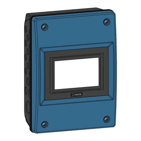
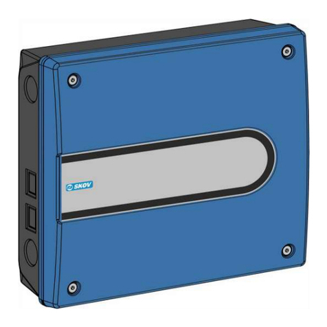
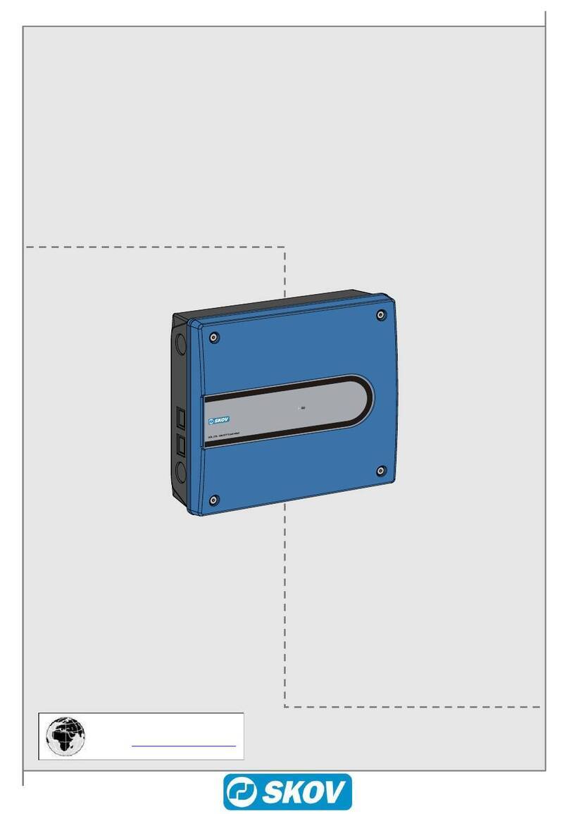
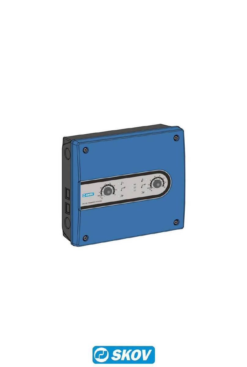
Skov DOL 43X cULus User manual

DOL 43X cULus
Climate Controller
Technical User Guide
604439 • 2022-01-17


DOL 43X cULus
Technical User Guide 3
Product and Documentation Changes
SKOV A/S reserves the right to change this document and the product herein described without further notice.
In case of doubt, please contact SKOV A/S.
The date of change appears from the front and back pages.
IMPORTANT!
Notes concerning alarm systems
Breakdowns, malfunctions or faulty settings may cause substantial damage and financial losses when regulat-
ing and controlling the climate in a livestock house. It is therefore essential to install a separate, independent
alarm system that monitors the house climate concurrently with the climate and production controller. According
to EU-directive No. 98/58/EU, an alarm system must be installed in all mechanically ventilated houses.
We would like to draw your attention to the fact that the product liability clause of general terms and conditions
of sale and delivery specifies that an alarm system must be installed.
Note
• All rights belong to SKOV A/S. No part of this manual may be reproduced in any manner whatsoever without
the expressed written permission of SKOV A/S in each case.
• All reasonable efforts have been made to ensure the accuracy of the information contained in this manual.
Should any mistakes or imprecise information occur in spite of this, SKOV A/S would appreciate being noti-
fied thereof.
• Irrespective of the above, SKOV A/S shall not accept any liability with regard to loss or damage caused or
alleged to be caused by reliance on any information contained herein.
• Copyright by SKOV A/S.

DOL 43X cULus
Technical User Guide
1 Product survey ...............................................................................................................................................5
2 Mounting guide...............................................................................................................................................6
2.1 Mounting of house controller ................................................................................................... 6
3 Installation guide ............................................................................................................................................7
3.1 Electrical connection................................................................................................................. 7
3.1.1 Connection of cables ................................................................................................................... 7
3.2 Positioning of jumper ................................................................................................................ 7
3.3 Setting CAN address ................................................................................................................. 8
3.4 Setting CAN termination jumpers ............................................................................................9
3.5 Setting CAN protocol jumper.................................................................................................. 10
3.6 Overview of connection terminals ......................................................................................... 11
3.6.1 Power supply (-K1.1) ................................................................................................................. 11
3.6.2 Main module (-K1.2) .................................................................................................................. 11
3.6.3 I/O module (-K1.3) ..................................................................................................................... 11
3.6.4 Loop modules (-K1.5) and (-K1.6) ............................................................................................. 11
3.6.5 Power supply (K1.7)................................................................................................................... 11
3.7 Supply voltage for I/O module / main module....................................................................... 12
4 Technical data...............................................................................................................................................13
4.1 Dimensioned sketch ................................................................................................................ 15
DOL 43X cULus
Technical User Guide 5
1 Product survey
Standard DOL 43X hardware with 12 relays. Inputs and outputs are described below.
The 0-10 V inputs and outputs of the main module can be configured in the following way:
• 11 inputs and 2 output - or
• 9 inputs and 4 output - or
• 7 inputs and 6 outputs
DOL 430 series
Small and large
12RL, 22RL, 32RL and 42RL
10 "
The DOL 43X software is supplied as:
System software: basic functionality.
Software update: new version of existing software with new functionality.

DOL 43X cULus
6 Technical User Guide
2 Mounting guide
2.1 Mounting of house controller
1. Place the controller with the display (A) at eye level for the daily user.
2. The controller must be mounted on the wall with the cable glands knock-outs facing downward.
3. Remember free space around the cabinet:
• 43cm (B) so that the front panel can be placed on top of the cabinet base during service.
• 10 cm (C) below the cabinet base to enable air cooling.
4. Place the enclosed conduit plate / 2 plates in the bottom of the cabinet, at the inside (D).
5. Terminal Q1 - Q5 - F6 (E) must only be connected with ”301209 Cable 278T/378T 13 core
1340mm” supplied with the DOL 278T emergency opening.

DOL 43X cULus
Technical User Guide 7
3 Installation guide
3.1 Electrical connection
The installation, service and troubleshooting in connection with electrical equipment must be car-
ried out by specialists in accordance with applicable national standards.
The installation of a circuit-breaker is required for each motor and power supply to facilitate volt-
age-free work on the electrical equipment.
• It must be suitably located and easily reached.
• It must be marked as the disconnecting device for the equipment.
Circuit-breaker is not supplied.
3.1.1 Connection of cables
Connect Cables according to the circuit diagrams that correspond to the system.
3.2 Positioning of jumper
The jumper is only present on I/O module type 3.
AI DI Temperature sensor

DOL 43X cULus
8 Technical User Guide
3.3 Setting CAN address
Each I/O module must have a specific CAN address so that the controller can communicate with it. The address
of the individual module corresponds to the address in the controller’s Technical | Installation | Manual in-
stallation | Additional I/O modules menu.
Set the I/O Modules' Rotary switches as follows:
Module 1Type 3 10RL 8AI 8AO Address=1
Module 2Type 3 10RL 8AI 8AO Address=2
Module 3Type 3 10RL 8AI 8AO Address=3
Module 4Type 3 10RL 8AI 8AO Address=4
I/O module

DOL 43X cULus
Technical User Guide 9
3.4 Setting CAN termination jumpers
The modules are controlled via CAN bus communication. To obtain a safe communication between the mod-
ules, it is important that the CAN termination jumpers are set correctly. The jumper must be ON on the module
where communication ends.
Example of the setting of a CAN termination jumper on the main module.
Example of the setting of CAN termination jumpers on the main module and two I/O modules.

DOL 43X cULus
10 Technical User Guide
3.5 Setting CAN protocol jumper
CAN protocol jumpers are factory-set to CANopen.

DOL 43X cULus
Technical User Guide 11
3.6 Overview of connection terminals
3.6.1 Power supply (-K1.1)
3.6.2 Main module (-K1.2)
3.6.3 I/O module (-K1.3)
3.6.4 Loop modules (-K1.5) and (-K1.6)
Loop module (-K1.5) is connecting all 115V / 230V L, N and functional-earth together.
Loop module (-K1.6) is connecting 24V for motor supply and 24V 0.8A for sensors.
3.6.5 Power supply (K1.7)

DOL 43X cULus
12 Technical User Guide
3.7 Supply voltage for I/O module / main module
Power supply 1x230 V+ FE
1 or more modules

DOL 43X cULus
Technical User Guide 13
4 Technical data
Electrical
Rated voltage V AC 100 – 240
Operating voltage V AC 90 – 264
Frequency Hz 50/60 (47 – 63)
Output W80
Max. current consumption A1.8 A at 115 V AC / 1.2 A at 230 V AC
Main module
Configurable main module. Number 0-10 V:
-11 inputs and 2 outputs – or
- 9 inputs and 4 outputs – or
- 7 inputs and 6 outputs
Inputs 7 x 0-10 V DC input impedance 2.1 mOhm.
Outputs/power supply 2 x 15 V DC power supply +/- 10 % max. 40 mA in total.
2 x motor supply 24 V DC +/- 20 % max. 0.4 A (in total for the entire
controller incl. I/O modules).
2 x supply for winch motor potentiometer 10 V DC max. 40 mA in total.
2 x 0-10 V DC output impedance 100 Ohm.
Relays 12 x NO/NC potential free
Max. voltage/current at resistive load 250 V AC / 5 A AC.
Max. voltage/current at inductive load 250 V AC / 2A AC CosPhi 0.8.
1 x alarm relay NC, max. 24 V AC 2 A, min. 12 V AC 10 mA (resistive
load).
Loop module - K1.6
Supply 1 x sensor / motor supply 24V DC +/- 20 %, 0.8 A.
DIN-Rail supply
Power supply 1 x sensor supply 12V DC +/- 20% 0.8 A.
I/O module type 15
I/O type 15, 10RL 8AI 8AO No jumpers. Requires external resistors for use with e.g., water me-
ters. Comes with resistors.
Inputs 8 x 0-10 V DC input impedance 2.1 mOhm.
Pulsing Inputs
(e.g. water meter, energy
meter)
Minimum pulse length: 75 ms.
Minimum pulse interval: 75 ms.
Maximum frequency/pulse per sec.: 6 Hz.
Outputs/power supply 8 x 0-10 V DC output impedance 10 Ohm.
1 x motor supply 24V DC +/- 20 %, 0.4 A (in total for the entire con-
troller incl. I/O modules).
Relays 10 x NO/NC potential free max.
Max. voltage/current at resistive load 250 V AC / 5 A AC.
Max. voltage/current at inductive load 250 V AC / 2A AC CosPhi 0.8.
I/O module type 3
IO type 3, 10RL 8AI 8AO With jumpers for configuration of inputs.
Inputs 8 x 0-10 V DC input impedance 2.1 mOhm.
Pulsing Inputs
(e.g. water meter, energy
meter)
Minimum pulse length: 75 ms.
Minimum pulse interval: 75 ms.
Maximum frequency/pulse per sec.: 6 Hz.

DOL 43X cULus
14 Technical User Guide
Outputs/power supply 8 x 0-10 V DC output impedance 10 Ohm.
1 x motor supply 24V DC +/- 20 %, 0.4 A (in total for the entire con-
troller incl. I/O modules).
Relays 10 x NO/NC potential free max.
Max. voltage/current at resistive load 250 V AC / 5 A AC.
Max. voltage/current at inductive load 250 V AC / 2A AC CosPhi 0.8.
Network
Network interface 2 x 10/100 BASE+TX RJ 45
USB 2 x USB 2.0 A type
Environment
Operating temperature °C (°F) -10 to +45 (+14 to 113)
Storage temperature °C (°F) -25 to +60 (-13 to +140)
Ambient humidity, operation % RH 0-80
Protection class IP 54 (splash-proof).
It is assumed that the base is level, i.e. ≤ 1.5 mm difference of height
and that the screws of the front panel are tightened with min. 1.5 Nm.
Altitude Max. 2000 m above sea level.
Positioning Must be placed indoor in a separate non hazardous control room.
Mechanical
Cable knock-out punches 30 x M25 for metrical cable gland.
Cable glands UL/CSA approved glands (M25 or PG16 with adapter) in areas where
glands are allowed.
Conduits in accordance with
NFPA 70
UL/CSA approved conduits in accordance with NFPA 70 (M25 or
PG16 with adapter) in areas where glands are not allowed.
Cables All cables must go through the M25 cable gland/conduit knockouts in
accordance with NFPA 70 in the bottom of the cabinet, when the con-
troller is hanging on the wall.
Terminal blocks Tighten all terminal blocks with 0.5 Nm of torque.
High and low voltage sepa-
ration
All 10 - 12 relay contacts on the modules must only be connected to
one type of voltage, e.g. 24 V DC or 230 V AC. 24 V DC and 230 V
AC must not be mixed.
The small alarm relay at terminal B12 and B13A is only for 12 V.
External cables and wires
are only allowed at:
Insulation of minimum 300 V.
Size minimum 18 AWG / 0.82 mm2.
Use copper conductors only.
Overvoltage category II max. 300 V.
Polution degree 3.
Shipment
Large Small
Dimensions (H x W x D) mm 381 x 568 x 170 381 x 400 x 170
Dimensions crated H x W x
D
mm 421 x 608 x 230 425 x 555 x 195
Weight g8000 5900
Shipping weight g9400 7000

DOL 43X cULus
Technical User Guide 15
4.1 Dimensioned sketch

604439 • 2022-01-17 • en-US • Made in Denmark
SKOV A/S • Hedelund 4 • Glyngøre • DK-7870 Roslev
Tel. +45 72 17 55 55 • www.skov.com • E-mail: [email protected]
Table of contents
Other Skov Control System manuals

Skov
Skov DOL 278 User manual

Skov
Skov Grow-Box Manual

Skov
Skov DOL 78T-1 User manual

Skov
Skov DOL 532 Tunnel User manual

Skov
Skov DOL 278AT User manual

Skov
Skov DOL 278T User manual

Skov
Skov DA 3800 Installation instructions manual

Skov
Skov DOL 635 User manual

Skov
Skov DOL 635 User manual

Skov
Skov 278A User manual
Popular Control System manuals by other brands

Milltronics
Milltronics RH Series Instruction handbook

YASKAWA
YASKAWA yasnac lx3 instruction manual

Pulse Instruments
Pulse Instruments System 2 user manual

Micatrone
Micatrone MicaFlex FHC Programming manual

Gilderfluke
Gilderfluke Br-miniBrick4 manual

Sturtevant Richmont
Sturtevant Richmont TCVe2 user manual