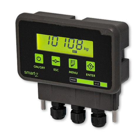
ESIT SMART User manual

SMART
INDICATOR
USER MANUAL
ver 1.0
MDK-SMAE-R00-081003
All manuals and user guides at all-guides.com

CONTENTS
Congratulations.......................................................................................................................3
GENERAL DESCRIPTION....................................................................................................4
ANNOUNCIATORS...............................................................................................................5
INDICATOR CONNECTIONS............................................................................................5
MENU SYSTEM......................................................................................................................6
DISPLAY SETTINGS ...........................................................................................................7
DECIMAL POINT SETTING...........................................................................................7
STEP VALUE SETTING...............................................................................................8
MAXIMUM ALLOWABLE WEIGHT SETTING..........................................................9
WEIGHT CALIBRATION ..................................................................................................10
ZERO CALIBRATION.....................................................................................................10
LOAD CALIBRATION.....................................................................................................10
COMMUNICATION SETTINGS .....................................................................................12
COMMUNICATION MODE SETTING.......................................................................12
SCALE IDENTITY NUMBER SETTING.....................................................................13
COMMUNICATION PARITY SETTING ....................................................................14
COMMUNICATION SPEED (BAUD RATE) SETTING ...........................................15
COMMUNICATION BIT SETTING............................................................................16
DECIMAL POINT COMMUNICATION SETTING..................................................17
TRANSMITTING WEIGHT VALUE FROM SERIAL LINE WITH KEY ...........19
RESETTING DISPLAY VALUE TO ZERO (ZEROISE) WITH KEY ...................19
ERROR CODES.....................................................................................................................20
2
All manuals and user guides at all-guides.com

Congratulations
… and thank you for choosing SMART, a weighing indicator specially suited for
weighing applications.
Apart from its unique toughness and extraordinary small size, SMART comes
packed with features that will help you in industrial weighing applications.
Like other indicators from ESIT, SMART is produced to meet highest quality
standards.
This guide introduces you to SMART and shows how to get the most out of it.
Please note that some of the functions described in this user’s guide are
depending on orders.
Should you need additional information on how to use them, contact
www.esit.com.tr
3
All manuals and user guides at all-guides.com

GENERAL DESCRIPTION
load cell input power, communication cables
Press... to...
Navigate (MENU access key)
Select a menu or transmit serial data
Go back one level in menu system or zeroise display value.
minus
center of zero
no-motion
4
All manuals and user guides at all-guides.com

ANNOUNCIATORS
No motion: Lights when there is no motion and goes off when there is movement
on the platform in the range of ±2e within 2 seconds.
Center of zero: Lights when displayed weight is zero and the internal count is
less than 1/4d. (d: The internal count which can increase the display by 1 step
value.)
INDICATOR CONNECTIONS
The multi-positioned printed circuit terminal block connections as follows. #1
indicates the leftmost terminal.
1 2 3 4 5 6 7 8 9 10 11 12 13 14 15 16 17 18 19 20 21
+Excitation
+LCinput
-LCinput
***
***
***
-Excitation
SHIELD
+DAC
-DAC
+V (9-36V)
0 Ground
Tx / B
Rx / A
***
RL1nopen
RL1comm
RL2nopen
RL2comm
RL3nopen
RL3comm
5
All manuals and user guides at all-guides.com

MENU SYSTEM
Press key to navigate in menu system.
IDENTITY MENU identifies the
serial number and version of the
indicator.
DISPLAY MENU: max. value, step
(e) and decimal point in LED display
are entered.
CALIBRATION MENU: set zero and
load values.
INPUT MENU: changes the
conversion rate of the analog-to-
digital converter.
OUTPUT1 (RELAY#1) MENU: set
point, set direction, hysteresis, and
time delay are entered.
OUTPUT2 (RELAY#2) MENU: set
point, set direction, hysteresis, and
time delay are entered.
OUTPUT3 (RELAY#3) MENU: set
point, set direction, hysteresis, and
time delay are entered.
COMMUNICATION PARAMETERS
MENU: comm. mode, scale number,
parity, baud rate, bit and decimal
point are entered.
6
All manuals and user guides at all-guides.com

DISPLAY SETTINGS
DECIMAL POINT SETTING
When the display resolution needs decimal point for fractional values, it is
possible to show it on the display.
(1) Press the navigation key until the
‘display’ menu appears
(2) Press to enter the ‘display’ menu
(3) Press the navigation key until the
‘decimal point’ menu appears
(4) Press to enter the ‘decimal point’ menu
(5) Scroll with the navigation key until you find the decimal point you
are looking for.
Implies
Implies
Implies
(6) Press in order to save the place of decimal point
(7) Press until normal operation menu appears
7
All manuals and user guides at all-guides.com

STEP VALUE SETTING
(1) Press the navigation key until the
‘display’ menu appears
(2) Press to enter the ‘display’ menu
(3) Press the navigation key until the
‘step value’ menu appears
(4) Press to enter the ‘step value’ menu
(5) Scroll with the navigation key until you find the step value you are
looking for.
Implies e = 1
Impliese=2
Impliese=5
Impliese=10
Impliese=20
Impliese=50
8
All manuals and user guides at all-guides.com

(6) Press in order to save the step value
(7) Press until normal operation menu appears
MAXIMUM ALLOWABLE WEIGHT SETTING
This value determines the maximum weighing range of the indicator. The
indicator will produce an error code when the weight value on the platform
exceeds MAX+ (9e).
(1) Press the navigation key until the
‘display’ menu appears
(2) Press to enter the ‘display’ menu
(3) Press the navigation key until the
‘max value’ menu appears
(4) Press to enter the ‘max value’ menu
(5) Press to enter the maximum allowable
weight value. Last stored value appears with
leftmost digit blinking.
(6) Blinking digit value can be incremented
with key; blinking digit can be changed
with key.
(7) To store the load calibration value press key.
(8) Press until normal operation menu appears
9
All manuals and user guides at all-guides.com

WEIGHT CALIBRATION
ZERO CALIBRATION
(1) Press the navigation key until the
‘calibration’ menu appears
(2) Press to enter the ‘calibration’ menu
(3) ‘Zero’ menu appears (blinking)
(4) After the platform is emptied, press to calibrate.
(5) ‘Load’ menu appears
(6) Press until normal operation menu appears or jump step (4) in load
calibration in order to make load calibration
“NORMAL OPERATION” means the indicator will start showing the weight on
the platform unless any key is pressed.
LOAD CALIBRATION
(1) Press the navigation key until the
‘calibration’ menu appears
(2) Press to enter the ‘calibration’ menu
(3) Press until the ‘load’ menu appears
(4) Press to enter the ‘load’ menu
10
All manuals and user guides at all-guides.com

(5) You can zeroise the platform by pressing in ‘load’ menu if needed
(6) LOAD THE PLATFORM WITH THE REFERENCE WEIGHT. THE
REFERENCE WEIGHT SHOULD BETTER BE AT LEAST HALF OF THE
LOAD CELL CAPACITY.
(7) Press to enter the load calibration
value. ‘0000’ appears with leftmost digit
blinking.
(8) Blinking digit value can be incremented
with key; blinking digit can be changed
with key.
(9) To store the load calibration value and
finish calibration, press key. Indicator
resets itself and restarts with new
calibration value.
ATTENTION: CALIBRATION VALUES CANNOT BE CHANGED UNLESS THE
CALIBRATION PLUG, PLACED BETWEEN AND KEYS, IS REMOVED
FROM THE BOARD.
11
All manuals and user guides at all-guides.com

COMMUNICATION SETTINGS
COMMUNICATION MODE SETTING
(1) Press the navigation key until the
‘communication’ menu appears
(2) Press to enter the ‘communication’ menu
(3) Press the navigation key until the
‘communication mode’ menu appears
(4) Press to enter the ‘communication mode’ menu
(5) Scroll with the navigation key until you find the communication
mode you are looking for
NO COMMUNICATION
CONTINUOUS TRANSMISSION OF 4
DIGIT WEIGHT VALUE
NOT AVAILABLE
ADDRESSED COMMUNICATION
(6) Press in order to save the communication mode
(7) Press until normal operation menu appears
12
All manuals and user guides at all-guides.com

Notes for MOD3 communication:
The transmission of weight value is performed when the indicator
realizes the code from the other side. By this way more than one indicator can
be connected to the same communication line. The data format is the same as
COMM 1.
For a PC to communicate with more than one indicator, this parameter
should be COMM3, and the communication hardware should be RS-485.
SCALE IDENTITY NUMBER SETTING
ONLY AVAILABLE IN COMMUNICATION MODE3
(1) Press the navigation key until the
‘communication’ menu appears
(2) Press to enter the ‘communication’ menu
(3) Press the navigation key until the
‘scale number’ menu appears
(4) Press to enter the ‘communication’ menu
(5) Last stored scale number value appears
with leftmost digit blinking
065 = hex41= “A”
NOTE: SCALE IDENTITY NUMBER RANGE IS FROM 0 TO 255
(6) Blinking digit value can be incremented
with key, blinking digit can be changed with
key
(7) To store the scale identity number press
key
(8) Press until normal operation menu
appears
13
All manuals and user guides at all-guides.com

COMMUNICATION PARITY SETTING
(1) Press the navigation key until the
‘communication’ menu appears
(2) Press to enter the ‘communication’ menu
(3) Press the navigation key until the
‘parity’ menu appears
(4) Scroll with the navigation key until you find the parity you are
looking for
ImpliesNOPARITY
ImpliesEVENPARITY
ImpliesODDPARITY
(5) Press in order to save the communication parity
(6) Press until normal operation menu appears
14
All manuals and user guides at all-guides.com

COMMUNICATION SPEED (BAUD RATE) SETTING
The number of communication bits sent per second is called BAUDRATE. The
allowable values are: 1200, 2400, and 4800.
(1) Press the navigation key until the
‘communication’ menu appears
(2) Press to enter the ‘communication’ menu
(3) Press the navigation key until the ‘baud
rate’ menu appears
(4) Press to enter the ‘baud rate’ menu
(5) Scroll with the navigation key until you find the baud rate you are
looking for
Implies 1200 baud communication
Implies 2400 baud communication
Implies 4800 baud communication
(6) Press in order to save the baud rate
(7) Press until normal operation menu appears
15
All manuals and user guides at all-guides.com

COMMUNICATION BIT SETTING
This parameter gives the number of bits in a communication byte. With 7 bits
communication 128 different characters can be coded. On the other hand 256
different characters can be coded with 8 bits communication.
(1) Press the navigation key until the
‘communication’ menu appears
(2) Press to enter the ‘communication’ menu
(3) Press the navigation key until the
‘communication bit’ menu appears
(4) Press to enter the ‘communication bit’ menu
(5) Scroll with the navigation key until you find the communication bit
you are looking for
Implies 7 bits communication
Implies8bitscommunication
(6) Press in order to save the communication bit
(7) Press until normal operation menu appears
Notes: The ASCII code for character ‘A’ is hexadecimal 41;
This is shown as:
7. 6. 5. 4. 3. 2. 1. 0.
7 bit x 1 0 0 0 0 0 1
8 bit 0 1 0 0 0 0 0 1
16
All manuals and user guides at all-guides.com

DECIMAL POINT COMMUNICATION SETTING
Communication with decimal point is available only in 8 bits communication.
Decimal point is sent in the most significant digit of the transmitted byte.
(1) Press the navigation key until the
‘communication’ menu appears
(2) Press to enter the ‘communication’ menu
(3) Press the navigation key until the
‘communication decimal point’ menu appears
(4) Press to enter the ‘communication decimal point’ menu
(5) Scroll with the navigation key until you find the decimal point
communication settings you are looking for
COMMUNICATION WITHOUT DECIMAL
POINT
COMMUNICATION WITH DECIMAL
POINT
(6) Press in order to save the decimal point communication settings
(7) Press until normal operation menu appears
17
All manuals and user guides at all-guides.com

Example data stream for mod1 in 8 bits and decimal point included communication:
Display
+1234 ‘+’ ‘1’ ‘2’ ‘3’ ‘4’ CR
Hex 2B 31 32 33 34 0D
+123.4 ‘+’ ‘1’ ‘2’ ‘3.’ ‘4’ CR
Hex 2B 31 32 B3 34 0D
-12.34 ‘-’ ‘1’ ‘2.’ ‘3’ ‘4’ CR
Hex 2D 31 B2 33 34 0D
If there is a decimal point on the display, then the corresponding digit is
sent with hex80 added to the ASCII value.
Character HEX Character HEX
0. B0 (30+80) 5. B5 (35+80)
1. B1 (31+80) 6. B6 (36+80)
2. B2 (32+80) 7. B7 (37+80)
3. B3 (33+80) 8. B8 (38+80)
4. B4 (34+80) 9. B9 (39+80)
Example data stream for mod3 (addressed communication):
If address (scale identity number) is set as 65 (41h), the indicator will send the
weight data after receiving
(Wake-up) Address
HEX FFh 41h
If the address is set to 0then the indicator will send the weight data after
receiving any character from the serial receive line. The address may take any
value from 0to 255.
When more than one SMART indicator is connected to the same transmission
line, then the devices should have RS 485 communication hardware and all should
have unique addresses.
18
All manuals and user guides at all-guides.com

TRANSMITTING WEIGHT VALUE FROM SERIAL LINE WITH KEY
If in the communication menu, the comm-3 was set the weight value can be
transmitted by pressing key from the serial line. In order to transmit the
data, no-movement state must be achieved.
RESETTING DISPLAY VALUE TO ZERO (ZEROISE) WITH KEY
To reset the weight value to zero, press key.
In order to perform this function, the indicator
should be in no-movement state appears as
After key is pressed, the value turns to
zero and center-of-zero symbol is lit.
19
All manuals and user guides at all-guides.com

ERROR CODES
During weight measurement in some cases the SMART indicator produces some
error codes. These codes and their probable reasons are as follows:
Error 01: Over range
More than MAX+ (9*e) of capacity
20
All manuals and user guides at all-guides.com
Other manuals for SMART
1
Table of contents
Other ESIT Measuring Instrument manuals
