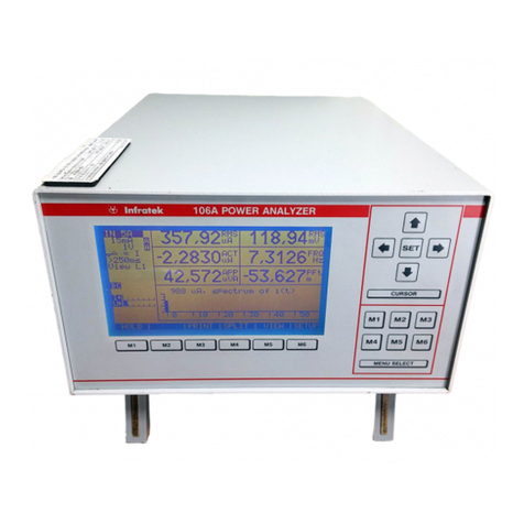
Infratek 106A User manual

USERS MANUAL 106A
SINGLE- AND THREE PHASE
POWER ANALYZER
Infratek

TABLE OF CONTENTS
1. Safety
1.1 Warnings
2. Introducing the High Speed Power Analyzer
2.1 Options and Accessories
2.2 Specifications
3. Mathematical Definitions used by the Power Analyzer
4. Getting Started
4.1 Front Panel and Rear Panel
4.2 Adjusting the Optimal Viewing Angle
4.3 Line Power
4.4 Turning the Power Analyzer On
4.5 Using the Function Keys
4.6 Selecting a Measurement Range
4.7 Taking Some Basic Power Measurements
5. Operating the Power Analyzer from the Front Panel
5.1 Introduction
5.2 Front Panel Operations
5.3 Current Input Selection
5.4 Range Selection / Auto Range Selection
5.5 Selecting Synchronization
5.6 Selecting the Measurement Time
5.6.1 Fast Response Power Analyzer (z-version)
5.7 Selection of AC- or DC+AC-Coupling
5.8 Changing the Display Configuration, Transformer Testing, Motor Testing
5.8.1 Changing the Harmonic Number
5.9 Main Menu Selection
5.9.1 Display Hold
5.9.2 Auto Range Selection
5.9.3 Selecting the Size of the Graphic Area
5.9.4 Selecting the Graphic Data
5.10 Short Time Integrator
5.11 Energy Computation
5.11.1 Set-up for Energy Measurement
5.11.2 Set-up for Charge Measurement

5.11.3 Starting and Stopping
5.11.4 Reading Energies at Precise instants of Time
5.12 Scaling of Current- and Voltage Inputs
5.13 Saving Instrument Settings
5.13.1 This is How you Save Your Desired Instrument Setting
5.13.2 This is How the 106A Starts Up in the Desired Configuration
6. Operating the Power Analyzer Using the Computer Interface
6.1 Introduction
6.2 Local and Remote Operations
6.3 Computer Interfaces
6.4 Setting Interface Parameters
6.5 Cabling the Power Analyzer to a Host
6.6 How the Power Analyzer processes Input
6.6.1 Input Terminator
6.6.2 Sending Commands to the Power Analyzer
6.6.3 How the Power Analyzer processes Output
6.6.4 Optimizing Speed for Data Transfer
6.7 Service Requests and Status Registers
6.8 Computer Interface Command Set
7. The Power Analyzer Options
7.1 Installing the Option Assembly
7.2 Output Connectors
7.3 Analog Inputs
7.4 Four Analog Outputs
7.5 Three Phase Current Sensor Module 0-100A
7.6 Printer Output
7.7 External Synchronization
7.8 Disturbance Prevention
8. Calibration Procedure
8.1 Calibration Cycle
8.2 Equipment Needed
8.3 Preparing for Calibration
8.4 Offset Adjustment and Calibration
8.4.1 Voltage Amplifier Calibration
8.4.2 Current Amplifier Offset Adjustment
8.4.3 Current Amplifier Calibration
8.4.4 Shunt Input Calibration
8.4.5 1A Input Calibration, Power Calibration

1-1
1. SAFETY
Before using the Power Analyzer, read the following safety information carefully.
In this manual „WARNING“ is reserved for conditions that pose hazards to the
user; „CAUTION“ is reserved for conditions that may damage your instrument.
Turn off power in the circuit to be measured.
Avoid working alone.
Follow all safety procedures for equipment being tested.
Inspect the test leads for damaged insulation.
Be sure the Power Analyzer is in good operating condition.
To avoid electrical shock, use caution when working above 30V dc or rms
Disconnect the live test leads before disconnecting the common test leads.
When making a current- or power measurement, turn the circuit power off
before connecting the Power Analyzer in the circuit.
Switching on inductive loads means large inrush currents. Take
precautions to avoid overloading the current channels by shorting the start-
up currents across the current inputs.
Switching off inductive loads or switching on rotating loads means large
voltages or extremely fast changing voltages on the Power Analyzer input
terminals. Such conditions may damage the instrument and are potentially
hazardous.
To comply with EN50081-1 the current- and voltage test leads must form 4
windings through ferrite toroid Philips Type 4322 020 9720 or equivalent.
Interface inputs/outputs must be shielded.
1kV burst test: use shielded input- and output cables.
The Power Analyzer complies with the safety standards IEC 1010-1,
EN61010-1.

1-2
1.1 WARNINGS
Before reading the manual or before using this instrument read carefully
the warnings below and make sure you understand them.
WARNING: Line Power
To avoid shock hazard, connect the instrument power cord to a power
receptacle with earth ground.
WARNING
The maximum floating voltage above earth ground on the current input
terminals and the voltage Lo-input terminals is 600V. Exceeding these
limits poses a hazard to the meter and operator.
WARNING
This instrument must be operated by qualified personnel.
WARNING
Refer all servicing of this instrument to qualified personnel. Before opening
case disconnect all leads connected to the instrument and finally
disconnect the power line cord.
WARNING
The specifications given in this manual solely describe the technical
properties of the instrument. They do not imply any other properties unless
it is explicitly said so.
WARNING
Use of this instrument in life support systems and in systems for people
transportation must be expressly authorized.
The authorization must be signed by the manufacturer of this Power
Analyzer.

2-1
2. INTRODUCING THE POWER ANALYZER
WARNING
Read the „Power Analyzer Safety“ in section 1 of this manual before using the
instrument.
This 1- and 3-phase Power Analyzer is designed for bench-top, field service,
and system application.
Some features provided by the Power Analyzer are:
Large, blue LCD monitor, 120 x 64mm (240x128 pixels).
Fully menu controlled operation with only 11 membrane keys.
Meter mode and graphics mode.
Measures and computes all electrical quantities of current, voltage, power,
energy and harmonics of current, voltage, and power simultaneously.
Frequency measurement 0.1Hz-400kHz.
AC, and AC+DC for individual quantities.
Built-in integrator.
Harmonic Analysis of current, voltage and power.
Bar graph and wave form display.
Wide voltage- and current range (1.5mA-40A).
High common mode rejection ratio.

2-2
2.1 OPTIONS AND ACCESSORIES
Option 01 contains the RS-232 serial interface, the Centronics printer output,
and the Windows Operating Software.
Option 02 contains the RS-232 serial interface, the Centronics printer output,
the IEEE-488 interface, and the Windows Operating Software. The IEEE-488
interface complies with the 488.1 and the 488.2 (1987) standard.
Option 03 contains the RS-232 serial interface, the Centronics printer output,
the IEEE-488 interface, four programmable 5V analog outputs, and eight
analog inputs, and the Windows Operating Software.
Option 04 contains a 3-phase current sensor module for currents up to 100A,
DC-10kHz. The supply for the current sensor module is provided by the Power
Analyzer.
Option 06 contains a comprehensive Lab View driver to operate the Power
Analyzer.
Option 07/M contains the Operating Software for Motor Testing.
Option 07/T contains the Operating Software for Transformer Testing
Option 08 contains TTL-input for external synchronization via analog-in analog-
out connector.
Option 09 contains the network to form artificial neutral.
Option 10 contains the 0-300A, 0-3000A flexible current clamps with connector
to clamp input of Power Analyzer. (one per phase)
Available accessories are described below.
ACS1: Current clamp with connector to the shunt input of the Power
Analyzer; range 0-200A, 0-1000A, DC-1kHz, 2 % accuracy
ACS2: Current clamp with connector to the shunt input of the Power
Analyzer; range 0-40A, 0-400A, DC - 2kHz, 2 % accuracy
ACS3: Soft carrying case provides protection for the instrument. Ideally
suited for service applications.
ACS4: Set of test leads, max. 32A, 1.5m; 2 red, 2 black.

2-3
ACS5: Shunt input connector.
ACS6: Service Manual
ACS7: Rack Mounting Kit
ACS8: Official Calibration Certificate from SCS (SCS: Swiss Calibration
Service)
ACS10: RS-232 / USB Adapter
ACS11: RS-232 / Ethernet Adapter
2.2 SPECIFICATIONS
This section defines the performance of the Power Analyzer. The user must be
aware that exposure of the Power Analyzer current inputs to their maximum
value will result in additional measurement errors. These errors add to those
given in the specification table.
1 A input: I0.5 A add 0.1 % x I2 (current in Ampere)
5 A input: I3 A add 0.018 % x I2 (current in Ampere)
30 A input: I15 A add 0.00014 % x I2 (current in Ampere)
Operating the 5A input at elevated currents (4A) will also affect the 30A input,
and visa versa.
Operating temperature range: 10C - 40C

2-4
Voltage 8 ranges: 0.3 V, 1 V, 3 V, 10 V, 30 V, 100 V, 300 V, 1000 V
Frequency range
DC, 0.1 Hz
–
1 MHz
Crest Factor
3:1 at 50 %
full scale (fs)
Input Impedance 1 MOhm
Common Mode
50 Hz/100 kHz
160 dB/100 dB
Standard accuracy 23°C; rms, mean, rectified mean; 0.3 V typ.
1 Hz–1 kHz ±(0.1 % rdg + 0.1 % range)
DC, 1 kHz–10 kHz ±(0.2 % rdg + 0.2 % range)
10 kHz-100 kHz ±(0.3 % / range + 0.04 % /kHz rdg)
100 kHz
-
300 kHz
±(0.3 % / range + 0.04 % /kHz rdg), typ.
Improved accuracy
±(0.05 % rdg + 0.07 %
rng)
DC: typical
Current 13 ranges: 1.5 mA, 5 mA, 15 mA, 50 mA, 150 mA, 500 mA,
1.5 A, 5 A; 1, 3, 10, 30, 100 A.
Max. 1A, 5 A, 30 A, resp.
Frequency range DC, 0.1 Hz-300 kHz /
1MHz
Crest Factor
3:1 at 50 % full scale (fs)
Common Mode 50 Hz/100 kHz 160 dB/120 dB
Standard accuracy 23°C; 1A-, 5A-, shunt input 30 A input
1Hz-1kHz ±(0.1% rdg+0.1% rng) ±(0.1% rdg+0.1% rng)
DC, 1kHz-10kHz ±(0.2 % rdg + 0.2 % rng) ±(0.7 % rdg + 0.2 % rng)
10kHz-100kHz ±(0.3 % range + 0.04 %/kHz rdg)
100kHz
-
300kHz
±(0.3 % range + 0.04 %/kHz rdg), typical
Lowest ranges 1.5 mA,
15 mA, 1 A: typical
Improved acc. 1Hz –
400 Hz
±(0.05% rdg + 0.07%rng)
DC: typical
Power 104 ranges corresponding to the products V x A.
Frequency range
DC, 0.1 Hz
-
300 kHz
45 Hz-65 Hz (0.1 % rdg + 0.01 % range)
1 Hz-1 kHz Add accuracy percent of current and voltage*
DC, 1 kHz-10 kHz Add* +0.04 % / (kHz PF)
10 kHz-100 kHz Add* +0.04 % / (kHz PF), typical
PF = 0 to ±0.1
PF = 0 to ±1
PF = 0 to ±1; DC: typical
PF = 1
Frequency
0.1 Hz-400 kHz, V triggered; Accuracy ±0.1 %
Computed
Values
Accuracy; Reactive Power, Var=±(VA2-W2)1/2, Apparent Power:
VA=Arms Vrms; Power Factor: PF=W/VA; Crest Factor:
CF=Ap/Arms, Vp/Vrms: Form Factor: FF=At/Arms, Vt/Vrms;
Impedance: Z=Vrms/Arms; Total Harm Dist: THD=Irms2 – Ifund2)1/2 /
Irms
Add accuracy percentage
figures of values involved
in computation.
Integrator Energy, Charge; Accuracy Wh, Vah, Varh, Ah; Basic accuracy of
integrated quantity.
Harmonic
Analysis
Frequency range of fundamental
2.5 Hz
-
100 kHz
Range of harmonic 1-99
Accuracy, Harmonic current and voltage
2 Hz-1 kHz ±(0.1 % rdg + 0.1 % range)
1 kHz-10 kHz ±(0.5 % rdg + 0.5 % range)
10 kHz
-
100 kHz
±(0.7 % range + 0.1 %/kHz rdg), typical
Display Liquid crystal graphic display with FL backlight
64 x 120 mm; 128 x 240 pixels
Power
AC, 50-400 Hz; Fuse: Power 85 V-240 V; 2 A, 15 VA
Dielectric
Strength
Inputs to case or power supply
Line input to case
Input to Input
2.5 kV/50 Hz/1 minute
1.5 kV/50 Hz/1 minute
4 kV/50 Hz/1 minute

2-5
Dimension
H x W x D; weight 150 x 235 x 320 mm; 4 kg
Options IEEE-488-2, RS232, Centronics printer output
4 programmable analog output; single-, sum-, or average values
4 analog inputs 0 - ±5 V, input impedance 200 kΩ
4 analog inputs 0 - ±10 V, input impedance 200 kΩ
Rack Mounting Kit / Windows Operating Software 95, 98, 2000, NT,
XP; transformer-motor testing
0 - ±5 V, accuracy 0.2 %
0 - ±5 V, accuracy 0.2 %
0 - ±10 V, accuracy 0.2%
1.5mA-1A
Inp/Shunt
Input
Shunt Hi
1 A input Hi against ILo
Shunt Lo
1 A input; mA: 1.5, 5, 15, 50, 150, 500, 1500
Shunt input, mV: 60, 60√10, 600, 600V√10,
6000, 6000√10
Input impedance:
60k
1A input: set scaling to 0.1
Shunt input: 60 mV
corresponds to 1.0000 A

3-1
3. MATHEMATICAL DEFINITIONS USED BY THE POWER
ANALYZER
RMS-value (1/T
o
T
i2 dt)1/2
Rectified mean 1/T
o
T
i dt
Mean value 1/T
o
T
i dt
Maximum max. (i) in averaging interval
Minimum min. (i) in averaging interval
Peak-to-peak max. (i) - min. (i) in averaging interval
Average Power P 1/T
o
T
u i dt
Apparent Power S RMS current x RMS voltage
Reactive Power Q (S2 - P2)1/2 for every harmonic
Crest Factor Maximum / RMS-value
Form Factor RMS-value / Rectified mean value
Frequency Number of zero crossings of current or voltage.
Power Factor P/S
Energies, Charge
0
t
xdt x=P, S, Q, rect. mean current
Total harm. Distortion THD (Irms2 - Ifund2)1/2/Irms
Impedance Vn/In phase n=harmonic 1-99
NOTE: RMS-, rectified mean-, mean-, maximum-, minimum-,
and peak-to-peak value apply to current and voltage.
Energies apply to real-, apparent-, and reactive power.
Charge applies to rectified mean current only.
Total harmonic distortion applies to current and
voltage.

4-1
4. GETTING STARTED
This section explains how to prepare the Power Analyzer for operation,
discusses general operating features, and explains some common
measurements.
4.1 FRONT PANEL AND REAR PANEL
The front panel in figure 4.1 shows the graphics display in the center and the
control keys to the right of the front panel. The five-cursor control keys are used
to move the cursor in 4 directions and select instrument settings with the SET-
key.
The six menu control keys at the bottom of the control field are used to select
the menus or settings shown at the bottom of the LCD.
The keys are ergonomically positioned for swift function selection.
Fig. 4.1 Power Analyzer Front Panel

4-2
The rear panel shown in figure 4.2 contains the input terminals on the right hand
side. The Hi- and Lo-voltage terminals are at the top. Below are the current input
terminals, two red terminals for 5A and 30A with one common Lo terminal. The
shunt input is equipped with a short connector. When not in use, this short
connector must be installed.
The three phase Power Analyzer has the inputs for phase 1 (L1) to the right,
phase 2 (L2) inputs are in the middle, and phase 3 (L3) inputs to the left.
On the left hand side of the rear panel are, from top to bottom, the RS-232
interface connector, the IEEE-488 interface connector, the Centronics printer
connector, and the analog in- and output connector.
To the far left is the power line cord connector for 50/60Hz line voltages in the
range 85V to 265V.
Fig. 4.2 Power Analyzer Rear Panel
4.2 ADJUSTING THE OPTIMAL VIEWING ANGLE
Operating the Power Analyzer on a table you may want to tilt the instrument.
This can be done by rotating forward the stand-offs at the bottom plate.

4-3
4.3 LINE POWER
WARNING
To avoid shock hazard, connect the Power Analyzer line cord to a receptacle
with earth ground.
Plug the line cord into the connector on the rear of the instrument. It will operate
on any line voltage between 85V ac and 265V ac without adjustment, and any
frequency between 50 and 400Hz.
4.4 TURNING THE POWER ANALYZER ON
To turn the instrument on activates the power line switch located near the power
receptacle on the rear panel.
When the instrument is turned on the display is set to its start-up configuration
with all values set to zero for about 2 seconds while the instrument performs an
internal self-test. After this self-test the power analyzer assumes its initial setting
as follows: the first line of the display number field shows the RMS current and
the RMS voltage. The second line shows power and frequency of current, and
the third line shows apparent power and power factor.
The fourth and fifth lines are graphic area. At start-up the harmonic bar graph of
current is displayed. The horizontal scale is numbered 0-59 referring to the
harmonics of current (N=0 is the DC component) and the vertical scale gives the
magnitudes of the harmonics of mA or A.
A 3-phase instrument will display values from phase L1.
4.5 USING THE FUNCTION KEYS
The two key control fields to the right of the front panel contain 11 keys. At the
top is the cursor control field; at the bottom is the menu control field.
The basic use of the two key control fields is as follows:
The cursor key control field is used to move the cursor to the desired position
on the display. Pressing the SET-key means that you want to modify this
position; this can be a position to the very left of the display (annunciator field)
such as 5A/30A input selection, or current range- or voltage range selection, or
synchronization to I or U (current or voltage of phase L1), or selection of
averaging time or selection of phase L1, L2, L3, or ALL display.
When you move the cursor to the display number field the display can be
reconfigured, that is, you can place at the selected position a different quantity.
The menu-key control field consists of keys F1 (M1) through F6 (M6) and go
with the 6 menus shown along the bottom of the display.

4-5
These menus are dynamically changing, depending on the cursor position and
other action you may take.
4.6 SELECTING A MEASUREMENT RANGE
When turning on the Power Analyzer the range selection is automatic. This is
indicated by the range annunciator’s on the left hand side of the display, e.g. 1A
A / 300mV A. To select the 5A- or 30A current input proceeds as follows: Move
the cursor to the „IN 5A“ annunciator and press the SET-key. A pull down menu
gives you 3 choices IN 5A/IN 30A/SHUNT. Now move the cursor to the 5A- or
30-A input annunciator and press the SET-key. The choice of current input
depends on the maximum current flowing in your circuit to be measured.
The A at the end of the range annunciator indicates auto ranging.
To select a current range move the cursor to the current range annunciator and
press the SET-key.
A pull-down menu of the possible ranges appears. Move the cursor to the
desired range and press the SET-key. The range annunciator with the new
range is now displayed and furthermore, the M indicates manual ranging for
current. Note that in the Three Phase Power Analyzer the ranges of the
channels L1, L2, L3 are the same.
WARNING
Make sure not to overload current inputs, damage may occur to the instrument.
Make sure when wiring the power analyzer in a circuit that you are wiring the
correct current input (5A or 30A) and make sure to select the correct input on
the power analyzer front panel (IN 5A or IN 30A).
4.7 TAKING SOME BASIC POWER MEASUREMENTS
WARNING
Read the Power Analyzer safety before operating this instrument.
The following procedures describe the basics of taking common power
measurements operating the Power Analyzer from the front panel. These
procedures are provided for the user who needs to get started quickly.
WARNING
To avoid electrical shock or damage to the Power Analyzer, do not apply more
than 850V peak between any terminal and earth ground.

4-5
The user should be well aware of the fact, that switching off inductive loads may
generate extremely fast and high voltage transients exceeding above limits.
To measure voltage, current, power and related quantities in a 3-phase circuit
connect the test leads as shown in figure 4.3 and described below.
Fig. 4.3 Power Analyzer Wiring in 3-Phase circuit
Turn off power in the circuit to be measured.
Break the circuit in each phase and connect phase L1 to the current input 1,
phase L2 to current input 2, and phase L3 to current input 3. The current
flows from source to load; as a consequence you must connect the Hi
current inputs to the source side and the Lo current inputs to the load side.
L1, L2, and L3 are connected to the Hi voltage inputs. All three Lo voltage
input terminals are connected together and are connected to neutral in a 4-
wire circuit. If you have no neutral available (3-wire circuit) connect the
voltage Lo-terminals to the grounding post on the Power Analyzer.

4-6
Switch on the Power Analyzer (it will be in automatic ranging). Select the
correct current input IN 5A or IN 30A as described in 4.6.
Turn on power to the load to be measured.
The Power Analyzer will automatically select the voltage range and displays
the following six electrical quantities (display top to bottom) RMS-current,
RMS-voltage, power, frequency, apparent power, and power factor of phase
L1.
The bar graph of current shows the harmonic content of phase L1.
Use the side menu to display values from phase L2, L3, and ALL.

5-1
5. OPERATING THE POWER ANALYZER FROM THE FRONT
PANEL
This section explains how to operate the instrument from the front panel.
5.1 INTRODUCTION
This Power Analyzer is a very advanced measuring system, equipped with
features not known to similar instruments. For example, you can select dc- or
ac-coupling for individual quantities, you can choose those quantities you want
to integrate, you can combine meter mode and graphics mode, you can obtain
harmonic analysis while the Power Analyzer is running in the meter mode. This,
and much more make this instrument a valuable tool in a wide range of
applications.
5.2 FRONT PANEL OPERATIONS
The following operations can be performed from the front panel:
Select manual or automatic ranging.
Select the 5A-, 30A-, or shunt input.
Select a current or a voltage range valid for phase L1, L2, and L3.
Select the measurement time.
Select AC- or DC-coupling for individual quantities.
Select integration for individual quantities.
Select display configuration.
Select display of a single phase L1, L2, or L3.
Select display „ALL“ of all 3 phases.
Select display HOLD.

5-2
Select graphics mode.
Select current- and voltage scaling.
Select input- output configuration.
5.3 CURRENT INPUT SELECTION
You have the choice of selecting one of four inputs 1A-, 5A-, 30A-, and shunt
input.
CAUTION
Due to different overload conditions of the current inputs you should, at all times,
know which one of the inputs is in use.
If you are using the 5A input you must select the 5A input indicated by the input
annunciator IN 5A or IN 30A. If it is not already selected proceed as follows:
move the cursor to the input annunciator, press the SET-key. A pull-down menu
appears for selection of the desired input. With cursor and SET you select the
5A current input. Now the current ranges are 15mA, 50mA, 150mA, 500mA,
1.5A, 5A, and 15A and the current display is scaled correctly.
Similarly, you select the 30A input with ranges 1A, 3A, 10A, 30A, 100A, and
300A.
Selecting the current shunt input will set the input ranges to 60mV, 60mV10,
600mV, 600mV10 6V, and 6V10 with a sensitivity of 1A/60mV. Using the
scaling capabilities of the Power Analyzer will give you direct read out in ampere
for your shunt or your current clamp (with voltage output).
Finally, the 106A also contains a low current 1A input via shunt connector and
current Lo. To use this input proceed as follows: select IN 5A input (ranges
15mA, 50mA, 150mA, 500mA, 1.5A, 5A, 15A). Scale current input to 0.1. Now
apply current from center pin of shunt input connector to current Lo. (low
terminal). The current ranges for the 1A input are now 1.5mA, 5mA, 15mA,
50mA, 150mA, 500mA, 1.5A. Using scaling 0.1 results in actual current and
power readings.
5.4 RANGE SELECTION / AUTO RANGE SELECTION
To select a current range, move the cursor to the current range annunciator.
Press the SET-key. A pull-down menu appears with the available ranges.

5-3
Move now the cursor to the desired range and press the SET-key again to
select that range. The current input is now in manual ranging indicated by the M
in the range annunciator.
In similar manner a voltage range is selected. Once you have selected a current
range the current input of the power analyzer is in manual ranging. You can
bring it back to auto ranging as follows: Move the cursor to the current range
annunciator. The second menu at the bottom of the display shows „AUTO“. If
you press the menu control key F2 (M2) the current range annunciator changes
to A at its very end indicating auto ranging.
Similarly you proceed to set the voltage input to auto ranging.
5.5 SELECTING SYNCHRONIZATION
Synchronization to current or voltage of phase 1 is possible. This
synchronization is required for the frequency measurement and partially also for
the harmonic analysis. Furthermore, the display values show better stability
when synchronization is properly selected. In a 3-phase Power Analyzer
synchronization to current or voltage of phase 1 is performed.
For selection of synchronization the following criteria applies:
Choose current synchronization when you are measuring current,
voltage, and power.
Choose voltage synchronization when you are measuring voltage only.
To select the type of synchronization you need move the cursor to the I / U
annunciator and press the SET-key. A pull-down menu appears. Move the
cursor to the required label and press the SET-key again!
5.6 SELECTING THE MEASUREMENT TIME
The measurement time sets the minimum time for signal averaging as well as
the time for display update. It can be varied from 100ms, 250ms, 500ms, 1s, to 2
seconds.
Furthermore, this averaging time is expanded to the end of the next signal
period. This results in stable readings down to 1Hz, frequency down to 0.1Hz.
Other manuals for 106A
1
Table of contents
Other Infratek Measuring Instrument manuals
