ESK Schultze ERM5 User manual

Elektronische Ölspiegel-
regulatoren ERM
5/ERM
5-CDH
Die genannten ESK-Komponenten sind ausschließlich
für die Anwendung in Kälteanlagen bestimmt.
Eine Inbetriebnahme ist nur unter der Voraussetzung
zulässig, dass der Einbau entsprechend den gesetz-
lichen Vorschriften erfolgte.
Alle Komponenten werden entsprechend den
geltenden Regeln konstruiert und gefertigt.
Das Produkt erfüllt folgende Bestimmungen:
¹EMV Richtlinie2004/108/EG
¹Niederspannungsrichtlinie 2006/95/EG
¹RoHS Richtlinie 2011/65/EU
Electronic Oil Level
Regulators ERM
5/ERM
5-CDH
The ESK components mentioned shall be
used in refrigeration plants exclusively.
Operation is only permitted if the installation was
carried out in accordance with legal regulations.
All components are constructed and produced in
accordance with the regulations in force.
The product fulfils the regulations of
¹the EMC-Directive 2004/108/EC
¹the Low Voltage Directive 2006/95/EC
¹the RoHS-Directive 2011/65/EU
Typ / type ERM5-0-BC
und /and ERM5-CDH-OC
Produkteigenschaften
Aufbau: Regulatorkörper aus Aluminium
Große Zuströmquerschnitte
Elektronikgehäuse aus Kunststoff
Schauglas für visuelle Füllstandskontrolle
Druck- und dichteunabhängige
Istwert-Erfassung des Füllstandes
Regelniveau: Mitte Schauglas
Opto-elektronisches Messverfahren
Zwei Relais zur Signalisierung und
Aufzeichnung von Betriebszuständen
Sicherheit: Verstärkte LEDs führen zu verringerter
Anfälligkeit durch verschmutztes Öl
Integriertes Notlaufprogramm sorgt selbst bei
widrigsten Umständen für die Ölversorgung
Vierfach-Messpunkte ermöglichen die Signal-
überwachungvonUnter-,aberauchÜberfüllung
Alarmfunktion bei Über-, Unterfüllung
und bei aktiviertem Notlaufprogramm
Product features
Design: Regulator case made of aluminium
Wide cross sections for oil flow
Electronic case made of plastic
Sight glass for visual oil level control
Actual level value detection
independent of pressure and density
Control level: middle sight glass
Opto-electronical measuring method
Two relays for signalisation / recording
of system operating conditions
Security: Reinforced LEDs lead to reduced sensitivity
caused by contaminated oil
Integrated emergency operation program arranges
for oil feed even in adverse conditions
Quadruple measure points enable signal control
of under- but also overfilling
Alarm function for over-, underfilling and for
activated emergency operation program
D Montage- und Betriebsanleitung
GB Installation and operating instructions
MADE
IN
GERMANY
!www.esk-schultze.de 1/8
F Instructions de montage et d‘utilisation
IInstallazione e Istruzioni per l‘uso

Anwendung
Beim Verbundbetrieb von Verdichtern werden Ölspiegelregu-
latoren zur Ölniveauregelung an die Verdichter angebaut. Die
Ölzufuhr erfolgt aus einem Reservoir. Für die korrekte Funktion
des elektronischen Regulators ist die leistungsmäßig richtige Aus-
legung aller Systemkomponenten wichtig.
Technische Daten
Taktung der Ölfüllung: Füllen: 5s
Messen: 10 s
Max. zulässiger Betriebsdruck: Typ ERM5: 60 bar
Typ ERM5-CDH: 130 bar
Typ ERM5-..-R717: 31 bar
Max. zul. Umgebungstemperatur: 45°C
Max. zul. Öl-/ Mediumtemperatur: 85° C
Spannungsversorgung: 230V 50/60 Hz – 1Ph ± 10 %
Ausgangsspannung Klemme 1/2/3: 230 V permanent
Max. Belastung Klemme 1/2/3: 50Hz 18 VA – 60Hz 15VA
Alarmrelaisbelastung: 250V/ 5 A
Magnetventil: Stromlos geschlossen – (NC)
Max. Schalthäufigkeit: 106
Schutzart: IP 54
Volumen: 0,05 l (dm3)
Gewicht: Typ ERM5: 1,3 kg
Typ ERM5-CDH: 1,6 kg
Kältemittel: HFKW/HFCKW, R744 (CO2),
Standardmäßig R290, R 600a
freigegeben für: R717 (nur Typ ERM5-..-R717)
Application
In multiple-compressor parallel systems oil level regulators are
installed to maintain an adequate oil level. Oil is fed convention-
ally from an reservoir.
The performance-oriented choice of all components will guaran-
tee the regular function of the electronic oil level regulator.
Technical data
Pulsed oil refilling process: Filling: 5sec
Measuring:10sec
Max. allowable working pressure: Type ERM5: 60 bar
Type ERM5-CDH: 130 bar
Type ERM5-..-R717: 31 bar
Max. allowable ambient temp.: 45°C
Max. allowable oil/ medium temp.: 85°C
Power supply: 230V 50/60 Hz – 1Ph ± 10 %
Power supply output terminal 1/2/3:
230Vpermanent
Max. load terminal 1/2/3: 50Hz 18 VA – 60Hz 15VA
Load. alarm relay max.: 250V/ 5 A
Solenoid valve: Normally closed – (NC)
Max. operating cycles : 106
Protection: IP 54
Volume: 0.05 l (dm3)
Weight: Type ERM5: 1.3 kg
Type ERM5-CDH: 1.6 kg
Refrigerants: HFC/HCFC, R744 (CO2),
Approved as R290, R 600a
standard for: R717
(type
ERM5-..-R717
only)
Technische Daten Technical data
Elektronischer Zul. Arbeitsdruckdifferenz Max. zul. Öldruck in Max. zulässiger Verdichteranschluss Ausführung
Ölspiegelregulator Ölrückführung der Ölrückführleitung Betriebsdruck
Electronic Allow. working pressure Max. allowable pressure Max. allowable Compressor connection version
Oil level regulator difference oil return in the oil return line working pressure
Abb. / Typ
Fig. / Type bar bar bar
a ERM 5-0-BC 60 3/4-Loch-Flansch / 3/4-bolt flange
b ERM 5-0-BC-L 3/4-Loch-Flansch lang / 3/4-bolt flange long
c ERM 5-OC 1,5 9 100 * 130 Gewinde / Thread: 1.1/8C-18 UNEF
d ERM 5-OC-B
Gewinde: 1.1/8C-18 UNEF
c ERM 5-CDH-OC 130
(Mit Gewinde G1C oder M36 auf Anfrage)
d ERM 5-CDH-OC-B Thread: 1.1/8C-18 UNEF (with threaded
connection G1C or M36 on request)
a ERM 5-0-BC-R717 31* 31 31 3/4-Loch-Flansch / 3/4-bolt flange
c ERM 5-OC-R717 Gewinde / Thread: 1.1/8C-18 UNEF
Geräte mit dem Nachsetzzeichen »-B« sind eine gespiegelte Version
des Regulator-Typ s, Aufbau un d Abmessunge n entspre chen dem Gru nd-
modell, eine Anleitung zum Umbau des Gerätes ist auf Anfrage erhältlich!
* Aufgrund der Löslichkeit von Kältemitteln in Ölen können
hohe Druckdifferenzen innerhalb des Ölreguliersystemes zu
einer vermehrten Schaumbildung führen. Somit kann es im
Einzelfall zur Beeinträchtigung der Schmierfähigkeit kommen.
Devices with suffix »-B« are mirrored versions of the
basic regulator types, dimensions remain unchanged.
A modification instruction is available on request!
* Due to the solubility of refrigerants in oil, in oil management
systems with high pressure differences foam building is possible.
Foam reduces the lubrication function of oil.
Elektron. Ölspiegelregulatoren
Electronic Oil Level Regulators
ERM
5
20151217
www.esk-schultze.de
!www.esk-schultze.de
2/8

181 (201)* 123
123
181
82 (96)*
82 (96)*
181 (201)*
85
110
181
120
145
* Typ / Type ERM5-CDH-..
Maßzeichnungen Dimensional drawings
Abbildung
Figurea
Abbildung
Figure b
Zu Abbildung a + b:
Verdichteranschluss »0-BC«
Rel. to Figure a + b:
Compressor connection »0-BC«
Abbildung
Figure c
Abbildung
Figure d
1Magnetventil Solenoid valve
2Öleintritt: 1/4“ Bördel Oil inlet: 1/4“ flare
mit 7/16“-UNF, Øi4 mm
with 7/16“-UNF, Øi4mm
(Ø6mmKupferrohr) (Ø6mmcoppertube)
3Schauglas Sight glass
4Adapter OC Adapter OC
(1.1/8“-18UNEF) (1.1/8“-18UNEF)
Elektron. Ölspiegelregulatoren
Electronic Oil Level Regulators
ERM
5
MADE
IN
GERMANY
!www.esk-schultze.de 3/8
20151204

1
6a
6b
2
3
4
5
7
8*/ 9*
1
6a
6b
2
3
4
5
2
Explosionszeichnung Exploded view
Installation und Inbetriebnahme
Der auf Dichtigkeit und Funktion geprüfte Regulator wird mit dem erfor-
derlichen Montagezubehör wie O-Ring, Befestigungsschrauben usw.
ausgeliefert.
Vor jedem Regulator ist ein Ölfilter zu montieren, um eine Verschmut-
zung des Magnetventilsitzes zu verhindern.
Die elektrotechnische Installation ist gemäß der gültigen Vorschriften
und dem nachstehenden Schaltschema vorzunehmen.
Der Ölstand vor dem ersten Einschalten des elektronischen Regulators
sollte mindestens 1/4 Schauglas betragen, um den Alarmzustand zu
vermeiden.
Das Magnetventil schließt nicht gegen verdichterseitigen Überdruck!
Es ist darauf zu achten, dass das Kältemaschinenöl nicht
verschmutzt wird, da sonst eine zuverlässige Funktion
der optischen Messung nicht gewährleistet ist.
Installation and put into operation
The regulator has passed the check on function and tightness and will
be delivered with the necessary mounting accessories, such as O-rings,
screws etc..
In front of every regulator an oil strainer has to be mounted, to avoid
soiling of the solenoid valve seat.
Concerning the electrical installation you have to pay attention to valid
standards and to the wiring diagram on the next page.
By putting the regulator into operation, the minimum oil level should be
1/4 sight glass at least, to avoid the alarm status.
The solenoid valve doesn‘t close against compressor positive pressure!
To ensure the correct function
of the optical measurement,
the oil must be free of contaminations.
Typ /Type ERM5-0-BC ..
Typ /Type ERM5-CDH-OC..
und/and ERM5-OC ..
(Abbildungen ähnlich / Illustrations show a similar type)
Geräte mit dem Nachsetzzeichen »-B«
sind eine gespiegelte Version des Regulator-
Typs, Aufbau und Abmessungen entsprechen
dem Grundmodell, eine Anleitung zum Umbau
des Gerätes ist auf Anfrage erhältlich!
Devices with suffix »-B«are mirrored versions
of the basic regulator types, dimensions remain
unchanged. A modification instruction is
available on request!
Adapter
OC
Elektron. Ölspiegelregulatoren
Electronic Oil Level Regulators
ERM
5
Magnetventilkörper (6a) und Prismen-
schauglas (3) dürfen nur im drucklosen
Zustand des Regulators gelöst werden. Das stirnseitig
eingeklebte Schauglas ist nicht demontierbar.
Do not untighten the solenoid valve body (6a)
or the prism sight glass (3), while the regulator
is under pressure! The glued-in sight glass on the face
side of the regulator is not removable.
1Regulator
Regulator
2O-Ring
O-ring OR-33 x 2,62
3Prismenschauglas
Prism sight glass
4Messeinheit
Measurement module
5Magnetventil-Stecker
Solenoid valve connector
6a Magnetventil: Ventil-Körper
Solenoid valve: Valve body
6b Magnetventil: Ventilspule
Solenoid valve: Coil
7O-Ring
O-ring OR-28,3 x 1,78
8Dichtring
Gasket ring DR-32 x 1,6
9O-Ring
O-ring OR-28,3 x 1,78
* Wahlweise mit Teflon-
oder O-Ring-Dichtung /
Optional with teflon
or O-ring gasket
20151222
www.esk-schultze.de
!www.esk-schultze.de
4/8

Klemmenplan / Connection scheme ElektrischerAnschlussplan/Wiringdiagram
Symbol Bedeutung / Meaning Klemme / Terminal Kontakt / Contact Bedeutung / Meaning
! ! "#! $%&'(! #! )&*+(,-(+,./!0#! ! 1!22!3! 45%&/,6(/&.'!78/&69!:!;&6+<+*!(,52=
! ! $G! G6A(!:!H6@<+A! I! ! !!
! ! $G! G6A(!:!H6@<+A! J! !! !
! ! >! ><///(.,(6!:!>(<,6&/! K!! 4L&++<+*'-(6'@6*<+*! ! ! 4#! 4.5%(6<+*!MN6!A(+!4,(<(6',6@9O6(.'!!!
! ! "#! $%&'(! P!! Q@/,&*(!'<LL/0! !! R<'(!M@6!,%(!5@+,6@/!5.65<.,!
Betrieb mit dem Kältemittel R744/CO2(Kohlendioxid)
ESK fertigt Komponenten für den sub- und transkritischen Betrieb.
Das Kältemittel ist farb- und geruchlos und bei einem Austritt nicht wahr-
nehmbar. Das Einatmen in erhöhter Konzentration kann zu Bewusstlosig-
keit und Ersticken führen. Die Entlüftung der Maschinenräume hat nach
EN378 zu erfolgen.
Die hohe Drucklage von CO2 stellt eine Gefahr dar und ist zu
beachten. Bei Anlagen-Stillstand steigt der Druck bei Umge-
bungstemperatur erheblich und es kann Berstgefahr bestehen. Der kri-
tische Punkt liegt bei 31°C und 74 bar. Absperrbare Anlagenteile sind mit
einem Sicherheitsventil auszurüsten (EN 378-2 und EN 13136).
Es darf kein Rohr am Sicherheitsventil angeschlossen werden, um beim
Öffnen ein Blockieren durch Trockeneisbildung zu vermeiden.
Es können sehr hohe Druckgastemperaturen auftreten, es besteht
Verbrennungsgefahr an Ölabscheider-Oberflächen und an Ölrück-
führ- und Druckausgleichsleitungen.
ESK-Komponenten dürfen nur für die freigegebenen Anwendungs-
bereiche eingesetzt werden. Bei Verwendung hochviskoser Kältemaschi-
nenöle >46 cSt ist die korrekte Funktion der Komponenten während der
Inbetriebnahme zu kontrollieren und zu überwachen. Gegebenenfalls sind
korrigierende Maßnahmen zu ergreifen.
Operation with refrigerant R744/CO2(carbon dioxide)
ESK produces components for sub- and transcritical running.
The refrigerant is colourless and odorless, and is not noticeable upon
discharge. Inhaling elevated concentrations can lead to unconsciousness
and suffocation. Ventilation of the machine rooms must be carried out in
accordance to EN378.
The high pressure condition of CO2is dangerous and must be
observed. In case of stop of the plant, the pressure elevates signifi-
cantly at the ambient temperature and there may be danger of burst. The
critical point is 31°C and 74bar. Parts of the plant that can be blocked must
be prepared with a safety valve (EN378-2 and EN 13136.)
To avoid, upon opening, a blocking caused by dry ice accumulation,
it is not allowed to connect a tube to the safety valve.
Very high discharge gas temperatures may develop. There is a risk
of burns at oil separator surfaces and at oil return and pressure
equilazation lines.
ESK components shall only be used within the approved application range.
Whenusinghighly viscosecoolingmachine oils>46 cSt,thecorrect function
of the components must be controlled and monitored during operation.
Where applicable, corrective measures must be taken.
Betrieb mit brennbaren Kältemitteln
Es besteht ein erhöhtes Risiko von leichter Entflammbarkeit,
toxischer Wirkung und Explosivität. Grundvoraussetzungen für die Her-
stellung und den Betrieb derartiger Anlagen sind Kältemittel spezifische
Kenntnisse und die absolute Einhaltung der Sicherheitsvorschriften für
Kältemittel. Es dürfen nur Komponenten eingesetzt werden, die von ESK für
solche Anwendungen konstruiert und freigegeben wurden.
Für die Herstellung, den Betrieb und den Service von Kälteanlagen
mitbrennbarenKältemittelnsind besondereBestimmungengültig.
Es sind Vorkehrungen zu treffen, die bei einem Kältemittelaustritt eine
gefahrlose Entlüftung gewähren, damit kein zündfähiges Gasgemisch
entsteht. In folgenden Normen sind zum Beispiel Bestimmungen über die
Ausführung von Anlagen beschrieben: EN 378, VBG 20
Operation with inflammable refrigerants
There is an increased risk of high inflammability, toxic effects and
explosiveness. Refrigerant-specific knowledge as well as strictly keeping
the safety regulations are fundamental requirements for the production
and operation of such plants. Only components shall be used that have
been constructed and released by ESK for such installations and/or opera-
tions.
For the production, operation, and service of refrigeration plants
with inflammable refrigerants, special regulations come into force.
Precautions must be taken so that, upon discharge of refrigerant, a safely
ventilation is guaranteed, in order to avoid the development of an ignit-
able gas mixture.The following norms describe e.g. regulations regarding
the execution of plants: EN 378, VBG 20
Bitte beachten Sie unsere speziellen Sicherheits-
hinweise zum Einsatz natürlicher Kältemittel!
Please follow our specific safety instructions
for operations with natural refrigerants!
Elektron. Ölspiegelregulatoren
Electronic Oil Level Regulators
ERM
5
MADE
IN
GERMANY
!www.esk-schultze.de 5/8
.1
.1
.1
.1
.1
.1
.1
.1
.1
.1
.1
.1
.1
.1
.1
.1
.1
.1
.1
.1
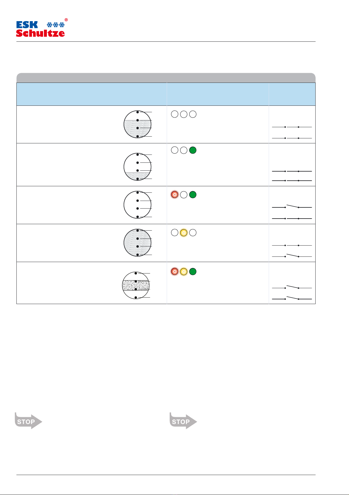
Nr.: Betriebszustand Füllstand im LED-Lichtsignal Kontakte
Prismenschauglas (rot A gelb A grün)
No.: Working state Oil level at the LED light signal Contacts
prism sight glass (red A yellow A green)
Funktionsbeschreibung Operation instruction
!"#$%&'(#)*(#%)+,%*-./0(%(
10*(/+2#3)((%#4-./5,0/*
# 6%7)-%#*8)(-.%2#9+
0):5)2#0%7%0#)*#;)220%#*),.(#,0/**
<"#10*(/+2#*)+=(#5+(%)((%#4-./5,0/*#
>3%**?5+=(#3@AB
# C.%#9)0#0%7%0#2%-&%/*%*#D%+%/(.#
(.%#;)220%#9E#(.%#*),.(#,0/**#
>;%/*5&)+,#?9)+(#3@AB
A"#10*(/+2#E'00(#(&9(F#GH0079&,/+,#8%)(%&#
DF8"#10*(/+2#D%)#4(/&(#2%&#I+0/,%
## J)0#0%7%0#2%-&%/*%*#)+#*?)(%#9E#
(.%#&%E)00)+,#9&#*(/&()+,#9)0#0%7%0
K"#10&H-=EH.&5+,#/5*#2%&#I+0/,%#%&.L.(#DF8"#
%&.L.(%&#M5&D%0,%.'5*%NGH00*(/+2#/5E,&5+2#
79+#M'0(%;)((%07%&0/,%&5+,
# O+-&%/*%2#9)0#&%(5&+#(.&95,.#(.%#*P*(%;#
9&#.),.%&#-&/+=-/*%#9)0#0%7%0#25%#(9#(.%#
&%E&),%&/+(#2)*?0/-%;%+(
Q"#R%&5+&%)+),5+,#);#S%&%)-.#3@#<#T#3@#A#
5+2#10*(/+2#*)+=(#5+(%@K#U#
V9(0/5ED%(&)%D#*(/&(%(#>*)%.%#W&=0'&5+,B
# X9+(/;)+/()9+#)+#(.%#/&%/#9E#3@#<#T#3@#A#
/+2#(.%#9)0#0%7%0#2%-&%/*%*#5+2%@K#U#
%;%&,%+-P#;92%#*(/&(*#>4%%#%Y?0/+/()9+B
M%)+#Z)-.(*),+/0# [# \#
V9#0),.(#*),+/0# ]# !^#
$&H+%#ZW6#0%5-.(%(_#@&9F%**9&#*-./0(%(#3/,+%(7%+()0_#
,%(/=(%(%&#GH0079&,/+,#>GH00%+#5+2#3%**%+B#D%,)++(
$&%%+#ZW6#*.)+%*_#?&9-%**9	?%+*#(.%#*90%+9)2## [# \
7/07%"#C.%#?50*%2#9)0#&%E)00)+,#?&9-%**#>E)00)+,#/+2#
;%/*5&)+,B#)*#*(/&(%2# ]# !^
V/-.#<#3)+5(%+#`+(%&EH005+,#D0)+=(#&9(%#ZW6# [# \
a%2#ZW6#*(/&(*#D0)+=)+,#/E(%&#
(89#;)+5(%*#9E#5+2%&E)00)+,# ]# !^
$%0D%#ZW6#D%,)++(#F5#D0)+=%+#>bD%&EH005+,B# [# \
c%0098#ZW6#*(/&(*#D0)+=)+,#>.),.#0%7%0B# ]# !^
a9(%#5+2#,%0D%#ZW6*#D0)+=%+#U#
,%(/=(%(%&#GH0079&,/+,#D%,)++(# [# \
a%2#/+2#P%0098#ZW6*#*(/&(*#D0)+=)+,#U#
C.%#?50*%2#9)0#&%E)00)+,#?&9-%**#)*#*(/&(%2# ]# !^
Der Notlaufbetrieb
Durch verunreinigtes Öl (zum Beispiel nach einem Motorschaden oder
Wicklungsbrand am Verdichter) können sich am Prismenschauglas Ver-
schmutzungen absetzen.
Treten, bedingt durch die Verschmutzung, Störungen an einem oder meh-
reren Messpunkten auf, wird ein Notlaufbetrieb aktiviert, der die Ölversor-
gung des Verdichters übernimmt.
Dass sich der Regulator im Notbetrieb befindet, wird durch das gleichzei-
tige Blinken der roten und gelben LEDs signalisiert. Die Kontakte [T\ und
]T!^ sind dabei permanent geöffnet. Das Öffnen des Magnetventils zeigt
die grüne LED an.
Der Ölstand im Verdichter wird je nach Verschmutzungsgrad des Prismen-
schauglases zwischen den Messpunkten 3@A und 3@K gehalten.
Der Notlaufbetrieb gewährleistet einen minimalen Füllstand und verhin-
dert so bis zum Eintreffen des Service den Ölnotstand.
Alarm » ÜBERFÜLLUNG« : Es wird empfohlen, den Verdichter
NICHT mittels dieser Funktion abzuschalten, denn:
befindet sich der Verdichter im Stillstand und die Überfüllungsanzeige
leuchtet, kann dieser nicht gestartet werden. Ein Reset ist nicht möglich.
gelangt während des Betriebs zusätzlich Öl über die Saugseite in das
Kurbelwannengehäuse, so dass Überfüllung signalisiert wird, wird der
Verdichter abgeschaltet.
Das Signal kann verwendet werden, um weitere Informationen
über den Anlagenzustand zu bekommen.
The emergency operation
Dirt at the surface of the prism sight glass, for example caused by engine
damage or a burn out of the motor winding, maybe generate failure mal-
functions on one or more points of measurement.
In such conditions a emergency operation will be activated. This operating
mode ensures the oil supply of the compressor.
The emergency operating mode is signalized by simultaneously blinking
of the red and the yellow LEDs. The contacts [T\ and ]T!^ of the relays are
open. The opening of the solenoid valve is signalized by the green LED.
In subject to the degree of pollution the oil level inside the crankcase of
the compressor will be adjusted between the measuring points 3@A and
3@K.
The emergency operation mode warranted a minimum oil level and pre-
vents hazardous oil deficiency until the arrival of a refrigeration service
technician.
Alarm » HIGH LEVEL« : It is recommended NOT TO USE this
function to switch off the compressor because:
the compressor can‘t start, if the high level alarm is activated. A reset is
not possible.
the compressor will switch off during working, if you have oil carry over
the suction line in the crankcase and the level increasing the high level
alarm.
The signal can be used to get further details about
the operating condition of the refrigerating plant.
Elektron. Ölspiegelregulatoren
Electronic Oil Level Regulators
ERM
5
www.esk-schultze.de
!www.esk-schultze.de
6/8

1 2 3 2 4
BI-BI BO DO / DO-1 1.3/4”-UN MR R
!
!
!
!
!
!!
"#$%&'&()
"#$%&'&()&*
"#$%&+)
"#$%&+)&(
"#$%&),-&+)
!
"#$%&),-&./
"#$%&
'
&()�/0
MA 1.1/8”-UNEF ME*1.1/4”-UNF TK* 3/4”-NPT GA-DO-CDH M38 x1.5
1PS234: 130 bar5
Elektron. Ölspiegelregulatoren
Electronic Oil Level Regulators
ERM
5
ཟ,6789:2;<:3=8!;><8!?@3A:87
!B!!C86<8!?D372EF<9:6;<
BB!!,87!234G!HFDIJJ6=8!(8:768KJ@7FL9!@8J!M87@6L>:87J!D68=:!
!NK87!@82!234G!HFDIJJ6=8<!O87:!EN7!@8<!#8=FD3:;7G
!?DD8!?@3A:87JI:H8!6<9DFJ6P8!$;<:3=8HFK8>Q7!
!1RL>73FK8<S!+<=!8:LG5!T!
Weitere Adapter auf Anfrage!
!
!!!!
ཟ,678L:!6<J:3DD3:6;<!U6:>;F:!3@3A:87
!B!!?D372!EF<L:6;<!6J!<;:!3P36D3KD8
BB!!V>8!234G!3DD;U3KD8!;A873:6<=!A78JJF78!;E!:>8!L;2A78J&!
!J;7!84L88@J!:>8!234G!3DD;U3KD8!P3DF8!E;7!:>8!78=FD3:;7G
!?DD!3@3A:87!96:J!6<LDF@8!2;F<:6<=!3LL8JJ;768J!
!1JL78UJS!+&76<=!8:LG5!T!Further adapters on request !
!!!!!
,68J8!WK87J6L>:!UF7@8!26:!=7QX:87!R;7=E3D:!
87J:8DD:S!86<8!.373<:68!EN7!?9:F3D6:I:!F<@!
#6L>:6=986:!93<<!<6L>:!=8=8K8<!U87@8<G!
V>8!=F6@8!U3J!U76::8<!U6:>!=783:8J:!L378S!
U8!L3<!<;:!=F373<:88!E;7!FA&:;&@3:8<8JJ!
;7!L;778L:<8JJG
!!
!Y'!K37! /Z'!K37! Z/!K37
Verdichter-Hersteller / Baureihe
Compressor manufacturer / line!!!!!!!!!!!!!!!!!
BITZER [M)RGG[\)RS!!!].)GG]^)S!!!]."GG]^"S!!![M"RGG[\"RS!!![M"GG[\"S!!![MR*GG[\R*S!!![M-)GG[\-)S!!!
ཟ ཟ
! [M,)GG[\,)S!![M)GG[\)S!!!_-*GG_)*S!!!_`GG_\S!!![aGG[\S!!!R[VGGR[.S!
ཟ ཟ
! [bGG[.S!!!YbGGY^S!!!![b"GG[^"S!!!Yb"GGY^"S!!!!
+!
ࠐࠗࠐࠗ ཟ
! _")GG_))S!!!![^)GG[))S!!!_""RGG_)"RS!![^"RGG[)"RS!!!_"-)GG_)-)S!![^-)GG[)-)S!!_"R*GG_)R*S!!!
+!
ࠛࠏ
+!
ࠛࠏ ཟ
! [^R*GG[)R*S!![^,)GG[),)S!!![^"GG[)"S!!!![,"GG[)"S!!!!R[()^S
!!
+!
ࠛࠏ
+!
ࠛࠏ ཟ
! _C)GG_^)S!!!_C"RGG_^"RS!!!_$-)GG_^-)S!!!_\R*GG_^R*!
ཟ
! _$V"GG_CV"S!!![cV)GG[CV)S!!![bV)GG[)V)S!!!Y^V"GGY)V"S!!!_$$"GG_,$"
ཟ߸߸ ཟ
O_GG! !! ! ! ! ! ! ! +!
ࠐࠗࠐࠗ
O[GGS!!!OYGG! !! ! ! ! ! ! !
ཟ
BOCK -.!1-?5![GGS!!-.!1-?5!%GGS!!!!-.!1-?5!YGGS!!!-.0GGS!!-.]GGS!!"d&-.[GGS!!"d&-.%GGS!!!!!
ཟ ཟ
! "d&-.YGGS!!"d&-.0GGS!!"d&-.]GGS!!-.[[GGS!!-.]]GGS!!-.d[!)+_!
ཟ ཟ
! ^_GGS!!^ZGGS!!^[GGS!!^%GGS!!^/[GGS!!^/YGGS!!^/]GGS!!?$GG!
+!
ࠐࠝ
+!
ࠐࠝ
!!! -.!1-?5!/_GGS!!-.!1-?5!__GGS!-.!1-?5!Z[GGS!"d&-./_GGS!!"d&-.__GGS!!"d&-.Z[GGS!!!!!!!
+!
ࠛࠏ
+!
ࠛࠏ ཟ
!
! -.d/_!)+_S!!-.d__!)+_S!!-.dZ[!)+_S!!-.d__GGS!!!!!!
+!
ࠛࠏ
+!
ࠛࠏ
!
ཟ
-.dZ[!)+_VS!!-.d[Y!)+_VS
ཟ߸߸ ཟ
!!!
-.d1-?d5_
!)+_V!
ཟ
^!\-ZS!!!^,C!\-Z! !! ! ! ! ! ! ! +!
ࠐࠝ
CARLYLE
,?GGS!!,#GGS!!'%^eGGS!!'%.GGS!!!'%-eGGS!!! !!
+!
ࠑࠠ
+!
ࠑࠠ
! 'Y"GGS!!'Y$GGS
!
ཟ ཟ
COPELAND ,_fS!!,ZGGS!!!!,[GGS!!,YGGS!!,gGGS!![$GGS!!!!Y$GGS!!,$GGS!!![))S!!Y))S!!]))S!!_(-S!!!CGGdS!!*GGdS!!],GGS!!,_,GGS!
ཟ ཟ
! ,CGGS!!,*GGS!
+!
ࠏ߸
+!
ࠏ߸
!!
! ,Y,GGS!!,GGYbhVS!!,]GG!
+!
ࠠ ཟ
! a(//$)"S!!a(%YCS!!GG0%CS!!GGg_CS!!GG__'CS!!a^_[S!!GG[]CS!!aR//$["S!!
+!
ࠛࠠ
+!
ࠛࠠ
!
! aR%YCS!!GG0%CS!!GGg_CS!!a#_%'CS!!GGZ]'CS!!a#//$GGa#/g$S!!a#g'C!
+!
ࠛࠠ
+!
ࠛࠠ
!
!a#//$GGa#/g$S!!a#g'C!
!+!
ࠛࠏ
+!
ࠛࠏ
࠽ࡀ
!
ࠛࠠ ࠽ࡀ
!
ࠛࠠ
!!
Bis / before 06/2014:!!!a(/%GG[]CS!!a(,_/GG[%CS!!a^'YGG/]CS!!a^,/ZCGG_%CS!!aR/%GG[%S!!a#g[GG/g'C!
+!
ࠢ࠙߸
+!
ࠢ࠙߸
Ab / since 06/2014:!!!!!a(/%GG//[CS!!a(,_/GG0YCS!!a^'YGG/]CS!!a^,/ZCGG_%CS!!aR/%GG[%S!!a#g[GG_%'CS!!a+GG! !+!
ࠛࠓ߸
+!
ࠛࠓ߸
! [$V*S!![$R*S!!
ཟ߸߸ ཟ
DANFOSS $VGGMS!!!*VaGGM!!! !
+!
ࠛࠏ
!+!
ࠛࠏ
!
ཟ
!
DORIN -[/S!!!-"d[/S!!-"c[/S!!-i[/S!!-0S!!!-"d0S!!!-"c0S!!C_GGS!!CZGGS!!!C[GGS!!!C%GGS!!!CYGGS!),R[/S!!R))jZ_GGR))j[S!!
ཟ ཟ
! -%S!!!-"d%S!!-"c%S!!_R&-%S!!-YS!!-"dYS!!-"cYS!!_R&-YS!!C0f!
+!
ࠠ
ཟ
!
! -//S!!-"d//S!!),R//S!!-i//S!!-_S!!-"d_S!!-Z_S!!-"dZ_S!!-Z%S!!-"dZ%S!!),RZ%S!!-"cZ%S!!!!-iZ%S!!C/GGS!!R))j/! +!
ࠛࠏ
!+!
ࠛࠏ
!
ཟ
! ),_R_''S!!),_''S!!),Z''S!!),[''S!!),R_R[''S! !! !
+!
ࠒࠝ߸߸
!! ! !!!!
+!
ࠕࠏࠒࠝࠑࠒࠖ
FRASCOLD ?GGS!!(GGS!!,GGS!!^GGS!!RGGS!!MGGS!!?&RCS!!,&RC!
ཟ ཟ
! kGGS!!k&RCS!!aGGS!!OGGS!!
+!
ࠠ
ཟ
!
! RGGVCS!!kGGVCS!!! !
+!
ࠛࠏ߸߸
!+!
ࠛࠏ߸߸
!
ཟ߸߸ ཟ
HKT !!! -R!h!-V!h-a!!h!+!/_GGZ[! !
+!
ࠛࠏ
!+!
ࠛࠏ
!
ཟ
GOELDNER! -R!h!-V!h-a!h!+!![[GG%[!!
26:!h!U6:>!-CV&?@3A:87!$!ZY!4!/G%!ϭ!/G/h]l&/]`\"^!!1i,G\7Gm!!-CVm!"RG_''Gg5
!!
+!
ࠛࠏ
!+!
ࠛࠏ
!
ཟ
Adaptersätze für Regulator-Montage Adapter kits for regulator installation
/! M87@6L>:87!
! );2A78JJ;7
_! +<=!
Z! ?@3A:87!
[! #8=FD3:;7
!
MADE
IN
GERMANY
!www.esk-schultze.de 7/8
20160308
A* 1.1/8”-UNF
!
!
!!
!
!
!!
!
!
!
!
!
!
!

Quality Products · Made in Germany
Qu
Qu
Qu
Qu
Q
Qu
Qu
u
l
l
l
al
al
i
it
it
t
y
y
Produc
t
ts
Q
Qu
Qu
u
al
al
it
it
y
Prod
uc
c
t
ts
ESK Schultze GmbH & Co. KG
Parkallee 8
D-16727 Velten
TEL: +49 (0) 3304 3903 0
FAX: +49 (0) 3304 3903 34
MAIL: info@esk-schultze.de
www.esk-schultze.de
Für technische Fragen steht Ihnen
unsere Service-Hotline zur Verfügung:
Montag bis Donnerstag: 9:00 Uhr BIS 17:00 Uhr
Freitag: 9:00 Uhr BIS 16:00 Uhr
TELEFON: +49(0)1805 375 463*
oder: + 49 (0) 1805 ESKINF*
* 5,88 Cent / 30 sec aus dem dt. Festnetz, abweichende
Preise für Anrufe aus dem Mobilfunknetz möglich
For technical questions contact
our technical support via phone:
Monday – Thursday: 9:00 AM to 5:00 PM
Friday: 9:00 AM to 4:00 PM (CET)
TEL.: +49(0)1805 375 463
or: + 49 (0) 1805 E S K I N F
Änderungen vorbehalten! ¹Subject to modification!
ESK
Komponenten für Kältetechnik, Klimaanlagen und Wärmepumpensysteme
Komponenten für den Einsatz von HFKW / HFCKW inkl. R410A
und von natürlichen Kältemitteln (R744, R717, R290 u.a.):
Ölabscheider ¹Hochleistungs-Ölabscheider ¹Ölabscheider-Sammler
Ölsammler ¹Ölspiegelregulatoren ¹Adapter ¹Ventile ¹Filter
Flüssigkeitsabscheider ¹Filtertrockner ¹Geräuschdämpfer
Flüssigkeitssammler ¹Füllstandskontrollen
Zubehör ¹Ersatzteile ¹Handelsware
ESK
Components
for cooling,
air conditioning and heat pump systems
Components for applications with HFC / HCFC incl. R410A
and natural refrigerants (especially R744, R717, R290):
Oil Separators ¹High performance Oil Separators ¹Oil Separator Reservoirs
Oil Reservoirs ¹Oil Level Regulators ¹Adapters ¹Valves ¹Strainers
Suction Line Accumulators ¹Filter Driers ¹Discharge Line Mufflers
Liquid Receivers ¹Level Control ¹Accessories ¹Spare parts ¹Merchandise
Elektron. Ölspiegelregulatoren
Electronic Oil Level Regulators
ERM
5
Sicherheitshinweise
Alle Komponenten und deren Zubehör sind für die Handhabung, Installa-
tion und den Gebrauch durch fach- und sachkundige Anlagenbauer, Instal-
lateure und Betreiber vorgesehen. Diese müssen über grundlegende Kennt-
nisse der Kältetechnik, der Kältemittel und der Kältemaschinenöle verfügen.
Unsachgemäße Handhabung oder Missbrauch
können zu Sach- oder Personenschäden führen.
Die Einhaltung der Einbauvorschriften und Anwendungsgrenzen
(Druck, Temperatur, Medien) sind Voraussetzung für eine sichere Funktion.
Vor Befüllung der Kälteanlage mit Kältemittel ist eine Dichtigkeitsprüfung
der Anlage, einschließlich der eingebauten ESK-Komponenten durchzu-
führen. Für die Druckprüfung darf kein reiner Sauerstoff verwendet werden.
Bei der Handhabung von Kältemitteln und Kältemaschinenölen und bei
der Durchführung von Arbeiten am gefüllten Kältekreislauf sind die jeweils
gültigen Unfallverhütungsvorschriften zu beachten.
Bei der Entsorgung von Altöl bzw. Kältemittel
sind die gesetzlichen Vorschriften einzuhalten.
Das Öffnen von ESK-Geräten darf nur im
drucklosen und abgekühlten Zustand erfolgen.
Magnetventilkörper (MV ohne Spule) und Prismenschauglas
dürfen nur im drucklosen Zustand des Regulators gelöst werden.
Das stirnseitig eingeklebte Schauglas ist nicht demontierbar!
Elektrische Anschlüsse nur durch Fachpersonal vornehmen!
Vor Öffnen des Gerätes spannungsfrei schalten!
Elektrische Anschlüsse vor Feuchtigkeit schützen!
Rücksendung von Komponenten
Vor der Rückgabe sind die Geräte vom Rücksender komplett zu entleeren,
das heißt, die Geräte werden ohne Öl und Kältemittel angeliefert.
Safety instructions
All components and accessories are for use and installation by
competent experts with fundamental knowledge of refrigeration
systems, refrigerants and refrigeration oils only.
Improper use can lead to material damage or personal injury.
Keeping all instructions (pressure, temperature, media)
creates the condition for a reliable function.
Before charging the refrigeration system with refrigerants you have to
make sure that the system, including the ESK-components, is tight. Do not
use oxygen for this test.
While handling refrigerants, refrigeration oils or handling with filled
up refrigeration systems, you have to pay attention to all regulations for
prevention of accidents.
If you have to dispose refrigerants or refrigeration oils,
make sure to keep all legal regulations.
ESK products must not be opened while they are
under pressure and until the vessel has cooled down.
Do not untighten the solenoid valve body (valve without coil) or the
prism sight glass, while the regulator is under pressure! The glued-in
sight glass on the face side is not removable.
Electrical connections must be made only by qualified staff!
Disconnect the unit from the power supply before opening it!
Protect electrical connections against moisture!
Return of components
When returning components the devices must be exhausted completely by
the return sender, i.e. the devices are delivered without oil and refrigerants.
www.esk-schultze.de
8/8
MAL-ERM5 2016.03-08
This manual suits for next models
1
Table of contents
Other ESK Schultze Controllers manuals


