Ekinex EK-HE1-TP User manual

1
Actuator / controller for
electrothermal actuators
Code: EK-HE1-TP
• Detection and reporting of short-circuit through moni-
toring of the current absorbed by the electrothermal
actuators connected to the outputs
• Detection and reporting of lack of supply voltage on
the electrothermal actuators connected to the outputs
(only if supplied at 230 Vac)
• Selective single channel enabling for only one con-
duction mode. In systems with radiant oor panels, the
function allows to simulate different steps of laying of
the pipes depending on the conduction mode in order
to achieve a higher cooling power
• Valve protection function (anti-seizure) during long
periods of inactivity
• Delayed activation of the outputs (in the range 5-40
s) in order to avoid power-absorption peaks by the
electrothermal actuators
• Automatic evaluation of the energy demand, available
as a communication object, to activate the thermal
generators and / or a circulator
• 4-channel and 4 inputs each channel logic functions,
to realize combinatorial building automation logic
through AND, OR, NOT and exclusive OR blocks
Other characteristics
• Housing in plastic material
• Mounting on 35 mm rail (according to EN 60715)
• Protection degree IP20 (installed device)
• Overvoltage class III (according to EN 60664-1)
• Classication climatic 3K5 and mechanical 3M2 (accor-
ding to EN 50491-2)
• Pollution degree 2 (according to IEC 60664-1)
• 4 modular units (1 unit = 18 mm)
• Weight 160 g
• Dimensions 72 x 90 x 70 mm (WxHxD)
Use
The device may be used as simple actuator or as actua-
tor / controller.
Actuator
The device receives controls and parameters via bus by
one or more KNX room temperature controllers.
• 8 or 4 ON / OFF or PWM independent outputs respec-
tively for 2-pipe or 4-pipe installations
• Heating / cooling changeover from bus
Actuator / controller
The device receives the temperature value via bus by one
or more KNX temperature sensors.
• 8 independent regulators (2-pipe systems) or 4 in-
dependent regulators (4-pipe systems), ON / OFF or
PWM
• Heating / cooling changeover from the bus (2 or 4-pipe
systems) or automatic switching based on the room
temperature (4-pipe systems)
• Management with single setpoint or absolute or rela-
tive setpoint with that may be activated through the
HVAC system mode
• Acquisition of two room temperature values received
via bus from other KNX devices with calculation of a
weighted average
• Surface temperature limiting function through value
received from the bus for heating applications with
radiant panels
• Anti-condensation protection function through sensor
status received from the bus for cooling applications
with radiant panels
• Energy saving functions with limitations and / or exten-
sion of comfort mode, with status received via bus from
window contacts or presence sensors
KNX device for control of electrothermal actuators for
zone valves in heating and / or cooling systems. It has
to be used in KNX installations for control of homes and
buildings.
Description
The EK-HE1-TP actuator / controller is an ekinex®KNX
S-mode bus device for the control of electrothermal ac-
tuators and / or motors for zone valves installed on di-
stribution manifolds of installations with radiant panels or
radiators. The 8 output channels use TRIAC to ensure a
noiseless command and a high number of cycles. The de-
vice may work in combination with NC (normally closed)
or NO (normallly opened) actuators and may be used in
installations with 2 or 4-pipe hydraulic distribution; in the
latter application it is possible to interlock the outputs,
completely closing the active valve before the opening of
the coupled valve, avoiding the mix of heating and col-
ling conveying uids. The device is provided with a mem-
brane keypad for manual control of the outputs and LED
indicators for the diagnosis of the operation state and of
alarms triggered by short-circuit of the outputs or power
failure. The device can be congured as simple actuator,
in combination with one or more KNX room temperature
controllers, or as actuator / controller with acquisition of
max 2 temperature values from KNX room temperature
sensors. The device integrates a KNX bus communica-
tion module and is realized for mounting on a standard
35 mm rail. The device is supplied by the KNX bus and
requires an additional 230 Vac or 24 Vac power supply for
the electrothermal actuators.
Functional characteristics
• 8 congurable channels for use with NC (normally
closed) or NO (normallly opened) electrothermal
actuators
• Independent conguration of each output channel
as actuator or actuator / controller for 2 or 4-pipe
systems, channel in parallel or as simple controlled
output through communication object
Datasheet STEKHE1TP_EN
REAEKHE1TP
2
Technical data
Power supply
• 30 Vdc from bus (electronics)
• 230 Vac 50/60 Hz or 24 Vac (loads)
• Current consumption from bus < 30 mA
• Power consumption from bus 720 mW
TRIAC outputs
• Nr: 8 independent (2-pipe systems)
4 coupled (4-pipe systems)
• Max current Imax: 2(1) A
• Max 4 electrothermal actuators in parallel for each
TRIAC output 0,5(0,3) A max
Environmental conditions
• Operating temperature: 0 ... + 55°C
• Storage temperature: - 25 ... + 55°C
• Transport temperature: - 25 ... + 70°C
• Relative humidity: 95% not condensing)
DCEKHE1TP
1) Programming pushbutton
2) Programming LED
3) Terminal block for KNX bus line
4) Field for physical address
Dev.
Line
Area
bus KNX
1A
21 43
1B 2A 2B
3A
109 1211
3B 4A 4B
65
L
87
N
1413 1615
L N
N
N
1
3
2
4
Membrane keypad
5) Signalling LED for xy channel (x = 1 ... 4; y = A, B)
6) Pushbutton for manual operation of xy channel (x = 1 ... 4; y = A, B)
7) Pushbutton for switching manual / automatic operation
8) LED for signalling manual / automatic operation mode
68
5
7
Note. To switch between manual mode and auto-
matic mode (and vice versa), press the appropriate
pushbutton for a time > 3 s.
i
LED Status Meaning
Single channel on Presence of power supply
off Absence of power supply
Group of 4
channels
slow blinking
(1 s)
Absence of power supply for a
4-channels group
Single channel fast blinking
(1 / 4 s) Short-circuit alarm*
Pushbutton ma-
nual / automatic
on Manual mode active
off Automatic mode active
Signalling LED
*) To acknowledge a short-circuit alarm, keep pressed the correspon-
ding channel pushbutton for a time > 3 s.
1A
21 43
1B 2A 2B
3A
109 1211
3B 4A 4B
65
L
87
N
1413 1615
L N
N
N
Terminal blocks for power supply and outputs
Nr. Sign Connection
1 1A TRIAC output for valve drive
21B TRIAC output for valve drive
3 2A TRIAC output for valve drive
42B TRIAC output for valve drive
9 3A TRIAC output for valve drive
10 3B TRIAC output for valve drive
11 4A TRIAC output for valve drive
12 4B TRIAC output for valve drive
6, 14 L Power supply phase (230 Vac or 24 Vac)
7, 8, 15, 16 N Power supply neutral (230 Vac or 24 Vac)
Mounting
The device has degree of protection IP20, and is there-
fore suitable for use in dry interior rooms. The housing
is made for rail mounting according to EN 60715 in bo-
ards or cabinets for electrical distribution. The correct
mounting is when the KNX bus terminal is located at the
bottom. When installing be sure to leave accessible only
the front panel; all other sides must not be accessible.
For the installation of the device on the rail proceed as
follows:
• with the aid of a tool bring the locking device in the fully
lowered position (1);
• place the upper edge of the rear inner prole on the
upper edge of the rail (2);
Note. For controlling loads different than electro-
thermal drives and servomotors for zone valve or
loads with rated current higher than the maximum
current, interface relays must be used.
i
Switching, display and connection elements
The device is provided with a membrane front keypad
with signalling LEDs and pushbuttons, programming LED
and pushbutton, a terminal for connecting the KNX bus
line and screw terminals for connecting the power supply
and the outputs.
Note. Use only servomotors for zone valve equip-
ped with stroke-end microswitches.
i

3
• rotate the device towards the rail (3);
• push the locking device upward until it stops (4).
Before removing the device, be sure that power supply
and controlled loads have been disconnected and the bus
terminal has been extracted from its slot. Use a screwdri-
ver to slide down the locking device and remove the de-
vice from the rail.
Connection of the KNX bus line
The connection of the KNX bus line is made with the ter-
minal block included in delivery and inserted into the slot
at the bottom of the housing.
Characteristics of the KNX terminal block
• spring clamping of conductors
• 4 seats for conductors for each polarity
• terminal suitable for KNX bus cable with single-wire
conductors and diameter between 0.6 and 0.8 mm
• recommended wire stripping approx. 5 mm
• color codication: red = + (positive) bus conductor,
black = – (negative) bus conductor
1 2
43
EKINSTGUIDAEKAB1TP
Note. When mounting the device in boards and ca-
binets it shall be provided the necessary ventilation
so that the temperature can be kept within the ope-
rating range of the device.
i
DCEKHE1TP
+
-
KNX
Bus
Dev.
Line
Area
bus KNX
1A
21 43
1B 2A 2B
3A
109 1211
3B 4A 4B
65
L
87
N
1413 1615
L N
N
N
Warning! In order to supply the KNX bus lines use
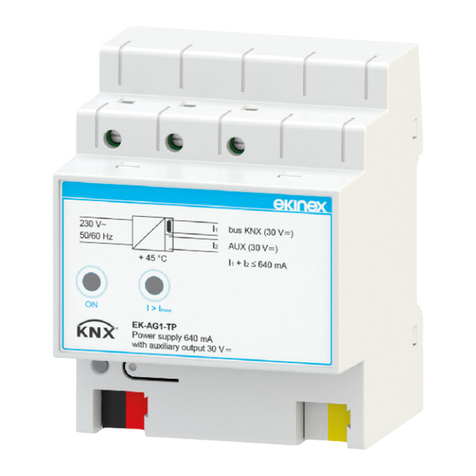
only KNX bus power supplies (e.g. ekinex EK-AB1-
TP or EK-AG1-TP). The use of other power supplies
can compromise the communication and damage
the devices connected to the bus.
!
Warning! The electrical connection of the device
can be carried out only by qualied personnel. The
incorrect installation may result in electric shock or
re. Before making the electrical connections, make
sure the power supply has been turned off.
!
Connection of the power supply
The connection of the 230 Vac or 24 Vac power supply is
made with the screw terminals (L, N) located at the top
front of the device.
Characteristics of the terminals
• screw clamping of conductors
• maximum cross section of conductor 2,5 mm²
• recommended wire stripping approx. 6 mm
• torque max 0,5 Nm
Warming! The number of electrothermal actuators
that can be connected in parallel to each output is
limited by the rated current and the starting current
of the device. Carefully check the information on
the technical documentation of the manufacturer of
actuators.
!
Connection of the outputs
The connection of the outputs is made with the screw ter-
minals located at the top front of the device.
Characteristics of the terminals
• screw clamping of conductors
• maximum cross section of conductor 2.5 mm² (single-
wire) or 1.5 mm² (multi-wire)
• recommended wire stripping approx. 6 mm
• torque max 0.8 Nm
To reduce the total starting current, in case of simulta-
neous activation of two or more output channels, it is pre-
ferable to enable the delayed start function during con-
guration via the ETS; in this case, each output channel
is activated with a delay time after the previous channel.
The delay is adjustable in the range 5 ... 40 s and is equal
for all channels.
Dev.
Line
Area
bus KNX
1A
21 43
1B 2A 2B
3A
109 1211
3B 4A 4B
65
L
87
N
1413 1615
L N
N
N
Connection in 4-pipe systems
L
N
230 Vac or
24 Vac
1 2
Valve actuator
(heating)
1 2
Valve actuator
(cooling)

4
Disposal
At the end of its useful life the product
described in this datasheet is classied
as waste from electronic equipment
and cannot be disposed together with
the municipal undifferentiated solid
waste.
Conguration and commissioning
Conguration and commissioning of the device require
the use of the ETS®(Engineering Tool Software) program
V4 or later releases. These activities must be carried out
according to the design of the building automation system
done by a qualied planner.
Note. The conguration and commissioning of KNX
devices require specialized skills. To acquire these
skills, you should attend the workshops at KNX cer-
tied training centers.
i
Note. When using in installations with 4-pipe
hydraulic distribution, the outputs have to be used
respecting the coupling between the channel pairs
1A-1B, 2A-2B, 3A-3B, 4A-4B.
i
Conguration
For the conguration of the device parameters the corre-
sponding application program or the whole ekinex®pro-
duct database must be loaded in the ETS program. For
detailed information on conguration options, refer to the
application manual of the device available on the website
www.ekinex.com.
Product
code
Application program
(## = release)
Communica-
tion objects
(nr. max)
Group
adresses
(nr. max)
EK-HE1-TP
APEKHE1TP##.knxprod
244 244
Commissioning
For commissioning the device the following activities are
required:
• make the electrical connections as described above;
• turn on the bus power supply;
• switch the device operation to the programming mode
by pressing the programming pushbutton located on
the front side of the housing. In this mode of operation,
the programming LED is turned on;
• download into the device the physical address and the
conguration with the ETS®program.
At the end of the download the operation of the device
automatically returns to normal mode; in this mode the
programming LED is turned off. Now the bus device is
programmed and ready for use.
Reset of the device
To reset the device remove the bus connection by ex-
tracting the bus terminal from its seat. Keeping pressed
the programming pushbutton, reinsert the bus terminal in
his seat; the programming LED blinks fast. Release the
programming button and remove the bus terminal again;
the reset was carried out. Now you need to address and
congure again the device via ETS.
Dimensions [mm]
72
70
5 25 20 20
45
90
Dev.
Line
Area
bus KNX
1A
21 43
1B 2A 2B
3A
109 1211
3B 4A 4B
65
L
87
N
1413 1615
L N
N
N
DQEKHE1TP
Warning! Incorrect disposal of this product may
cause serious damage to the environment and hu-
man health. Please be informed about the correct
disposal procedures for waste collecting and pro-
cessing provided by local authorities.
!
Warning! The reset restores the device back to the
state of delivery from the factory. The address and
the value of the parameters set during conguration
will be lost.
!
Marks
• KNX
• CE: the device complies with the Low Voltage Directi-
ve (2014/35/EC) and the Electromagnetic Compatibili-
ty Directive (2014/30/EC). Tests carried out according
to EN 50491-2:2010, EN 50491-3:2009, EN 50491-
4-1:2012, EN 50491-5-1:2010, EN 50491-5-2:2010,
EN 50428:2005 +A1:2007 + A2:2009
Maintenance
The device is maintenance-free. To clean use a dry cloth.
It must be avoided the use of solvents or other aggressive
substances.
Connection in 2-pipe systems
Dev.
Line
Area
bus KNX
1A
21 43
1B 2A 2B
3A
109 1211
3B 4A 4B
65
L
87
N
1413 1615
L N
N
N
L
N
230 Vac or
24 Vac
1 2
Valve actuator

5
Documentation
This datasheet refers to the release A1.0 of the ekinex®
device EK-HE1-TP, and is available for download at www.
ekinex.com as a PDF (Portable Data Format) le.
File name Device release Updating
STEKHE1TP_IT.pdf A1.0 11 / 2016
Warnings
• Installation, electrical connection, conguration and
commissioning of the device can only be carried out
by qualied personnel in compliance with the appli-
cable technical standards and laws of the respective
countries
• Opening the housing of the device causes the imme-
diate end of the warranty period
• In case of tampering, the compliance with the essen-
tial requirements of the applicable directives, for which
the device has been certied, is no longer guaranteed
• ekinex®KNX defective devices must be returned to the
manufacturer at the following address: EKINEX S.p.A.
Via Novara 37 I-28010 Vaprio d’Agogna (NO) Italy
Other information
• This datasheet is aimed at installers, system integra-
tors and planners
• For further information on the product, please contact
the ekinex®technical support at the e-mail address:
[email protected] or visit the website www.ekinex.
com
• Each ekinex®device has a unique serial number on
the label. The serial number can be used by installers
or system integrators for documentation purposes and
has to be added in each communication addressed to
the EKINEX technical support in case of malfunctio-
ning of the device
• KNX®and ETS®are registered trademarks of KNX
Association cvba, Brussels
© EKINEX S.p.A. The company reserves the right to make changes to this
documentation without notice.
Table of contents
Other Ekinex Controllers manuals

Ekinex
Ekinex KNX EK-FB1-TP User manual

Ekinex
Ekinex EK-HA1-TP User manual

Ekinex
Ekinex EK-FE1-TP User manual

Ekinex
Ekinex EK-AG1-TP User manual

Ekinex
Ekinex EK-HH1-TP Instructions for use

Ekinex
Ekinex EK-GC1-TP User manual

Ekinex
Ekinex EK-ET2-TP User manual

Ekinex
Ekinex KNX FF Series User manual

Ekinex
Ekinex EK-HH1-TP User manual

Ekinex
Ekinex 71 Series User manual
Popular Controllers manuals by other brands

Safeline
Safeline THOR Hardware manual

Siemens
Siemens Raja+ 3TE7431-2BC24-1A Series Installation, Maintenance & Troubleshooting Guide

Leroy-Somer
Leroy-Somer DIGISTART D3 Getting started guide

MicroStep
MicroStep CC-S1 user manual

Dolby Laboratories
Dolby Laboratories CP500 user manual

YASKAWA
YASKAWA MP2300 user manual