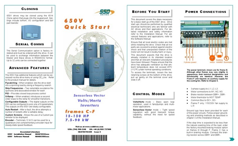
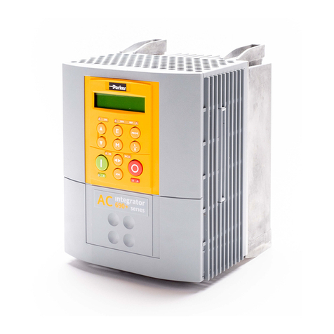
SSD Drives 650V User manual

Copyright 2005 SSD Drives Limited (formerly Eurotherm Drives Limited)
All rights strictly reserved. No part of this document may be stored in a retrieval system, or transmitted in any form or by
any means to persons not employed by an SSD Drives company without written permission from SSD Drives Ltd.
Although every effort has been taken to ensure the accuracy of this document it may be necessary, without notice, to
make amendments or correct omissions. SSD Drives cannot accept responsibility for damage, injury, or expenses
resulting therefrom.
650V AC Drive
Frames 1, 2, 3, C, D, E & F
Software Product Manual
HA466358U001 Issue 4
Compatible with Version 4.8 (onwards) Software

Cont.2
WARRANTY
SSD Drives warrants the goods against defects in design, materials and workmanship
for the period of 12 months from the date of delivery on the terms
detailed in SSD Drives Standard Conditions of Sale IA058393C.
SSD Drives reserves the right to change the content and product specification without notice.

Cont.3
Requirements
IMPORTANT: Please read this information BEFORE installing the equipment.
Intended Users
This manual is to be made available to all persons who are required to install, configure or
service equipment described herein, or any other associated operation.
The information given is intended to highlight safety issues, and to enable the user to obtain
maximum benefit from the equipment.
Complete the following table for future reference detailing how the unit is to be installed and
used.
INSTALLATION DETAILS
Serial Number
(see product label)
Where installed
(for your own
information)
Unit used as a:
(refer to Certification
for the drive)
RComponent RRelevant Apparatus
Unit fitted: RWall-mounted REnclosure
Application Area
The equipment described is intended for industrial motor speed control utilising AC induction or
AC synchronous machines.
Personnel
Installation, operation and maintenance of the equipment should be carried out by qualified
personnel. A qualified person is someone who is technically competent and familiar with all
safety information and established safety practices; with the installation process, operation and
maintenance of this equipment; and with all the hazards involved.
!
Safety Information

Cont.4
Hazards
WARNING!
This equipment can endanger life through rotating machinery and high voltages.
Failure to observe the following will constitute an ELECTRICAL SHOCK HAZARD.
This is a product of the restricted sales distribution class according to IEC 61800-3.
In a domestic environment this product may cause radio interference in which case
the user may be required to take adequate measures.
This product is designated as “professional equipment” as defined in EN61000-3-2.
Permission of the supply authority shall be obtained before connection to the low
voltage supply.
•The equipment must be permanently earthed due to the high earth leakage current.
•The drive motor must be connected to an appropriate safety earth.
•The equipment contains high value capacitors which take time to discharge after removal of
the mains supply.
•Before working on the equipment, ensure isolation of the mains supply from terminals L1,
L2 and L3. Wait for at least 3 minutes for the dc link terminals (DC+ and DC-) to discharge
to safe voltage levels (<50V). Measure the DC+ and DC- terminal voltage with a meter to
confirm that the voltage is less than 50V.
•Never perform high voltage resistance checks on the wiring without first disconnecting the
drive from the circuit being tested.
•When replacing a drive in an application and before returning to use, it is essential that all
user defined parameters for the product’s operation are correctly installed.
•This equipment contains electrostatic discharge (ESD) sensitive parts. Observe static
control precautions when handling, installing and servicing this product.
IMPORTANT: Metal parts may reach a temperature of 90 degrees centigrade in operation.
Application Risk
The specifications, processes and circuitry described herein are for guidance only and may need
to be adapted to the user’s specific application.
SSD Drives does not guarantee the suitability of the equipment described in this Manual for
individual applications.
Risk Assessment
Under fault conditions, power loss or other operating conditions not intended, the equipment
may not operate as specified. In particular:
•The motor speed may not be controlled
•The direction of rotation of the motor may not be controlled
•The motor may be energised
Guards
The user must provide guarding and /or additional safety systems to prevent risk of injury and
electric shock.
Protective Insulation
•All control and signal terminals are SELV, i.e. protected by double insulation. Ensure all
wiring is rated for the highest system voltage.
Note: Thermal sensors contained within the motor must be double insulated.
•All exposed metalwork in the drive is protected by basic insulation and bonding to a safety
earth.
RCDs
These are not recommended for use with this product but ,where their use is mandatory, only
Type B RCDs should be used.
!
Safety Information

Contents
Contents Page
Cont.5
Chapter 1 PROGRAMMING YOUR APPLICATION
Programming with Block Diagrams .............................................................1-1
Modifying a Block Diagram Over Comms ................................................................1-1
•Configuration and Parameterisation Modes.........................................................1-1
•Execution Rules...................................................................................................1-2
•Saving Your Modifications...................................................................................1-2
Function Block Descriptions.......................................................................... 1-3
Understanding the Function Block Description ..........................................................1-3
Function Blocks by Category ....................................................................................1-4
Function Blocks in Alphabetical Order ......................................................................1-5
•ANALOG INPUT ................................................................................................1-5
•ANALOG OUTPUT.............................................................................................1-7
•APP CONFIG .....................................................................................................1-8
•AT LOAD ...........................................................................................................1-9
•AT SPEED.........................................................................................................1-10
•AUTO RESTART ................................................................................................1-11
•AUTOTUNE .....................................................................................................1-12
•BRAKE CONTROL ............................................................................................1-13
•COMMS CONTROL .........................................................................................1-14
•COMMS PORTS ...............................................................................................1-15
•CURRENT LIMIT ...............................................................................................1-17
•CUSTOM MENU ..............................................................................................1-18
•DEMULTIPLEXER...............................................................................................1-19
•DIGITAL INPUT ................................................................................................1-20
•DIGITAL OUTPUT.............................................................................................1-21
•DISPLAY/KEYPAD .............................................................................................1-22
•DYNAMIC BRAKING.........................................................................................1-23
•ENCODER .......................................................................................................1-24
•ENERGY METER ...............................................................................................1-25
•FEEDBACKS .....................................................................................................1-26
•FLUXING .........................................................................................................1-28
•FLYCATCHING ................................................................................................1-31
•INJ BRAKING ...................................................................................................1-33
•INVERSE TIME ..................................................................................................1-34
•I/O TRIPS.........................................................................................................1-35
•LOCAL CONTROL ...........................................................................................1-36
•LOGIC FUNCTION ..........................................................................................1-37
•MINIMUM SPEED .............................................................................................1-41
•MMI ACCESS ...................................................................................................1-42
•MOTOR DATA .................................................................................................1-43
•MULTIPLEXER ...................................................................................................1-45
•PATTERN GEN .................................................................................................1-46
•PID ..................................................................................................................1-47
•PRESET ............................................................................................................1-49
•RAISE/LOWER ..................................................................................................1-51
•REFERENCE......................................................................................................1-52
•REFERENCE JOG .............................................................................................1-54

Contents
Contents Page
Cont.6
•REFERENCE RAMP ............................................................................................1-55
•REFERENCE STOP ............................................................................................1-57
•SEQUENCING LOGIC .....................................................................................1-58
•SKIP FREQUENCIES..........................................................................................1-60
•SLEW RATE LIMIT..............................................................................................1-62
•SLIP COMP ......................................................................................................1-63
•SPEED LOOP ...................................................................................................1-64
•STABILISATION ................................................................................................1-66
•STALL TRIP .......................................................................................................1-67
•TORQUE LIMIT ................................................................................................1-68
•TRIPS HISTORY.................................................................................................1-69
•TRIPS STATUS...................................................................................................1-70
•VALUE FUNCTION...........................................................................................1-73
•VOLTAGE CONTROL .......................................................................................1-80
•ZERO SPEED ....................................................................................................1-81
Normal/Heavy Duty Selection ....................................................................1-82
Chapter 2 PARAMETER SPECIFICATION
Specification Table: Tag Number Order....................................................... 2-2
MMI Parameters ......................................................................................... 2-13
Pref Cross Reference Table ....................................................................................2-16
Product-Related Default Values .................................................................2-17
* Frequency Dependent Defaults ............................................................................2-17
** Power Dependent Defaults.................................................................................2-18
Chapter 3 SERIAL COMMUNICATIONS
Communications Technology Options...........................................................3-1
ConfigEd Lite ..........................................................................................................3-1
Connection to the P3 Port .............................................................................3-1

Contents
Contents Page
Cont.7
Chapter 4 SEQUENCING LOGIC
Principle State Machine ................................................................................ 4-1
Main Sequencing States...........................................................................................4-1
State Outputs of the SEQUENCING LOGIC Function Block .......................................4-1
Transition of States..................................................................................................4-2
State Diagram ........................................................................................................4-3
External Control of the Drive ........................................................................4-4
Communications Command....................................................................................4-4
•Example Commands.............................................................................4-5
Communications Status ...........................................................................................4-6
Chapter 5 APPLICATIONS
The Default Application ................................................................................ 5-1
How to Load an Application .........................................................................5-1
Application Description ................................................................................ 5-1
Application 1 : Basic Speed Control (default) ............................................................5-3
Application 2 : Auto/Manual Control ......................................................................5-5
Application 3 Preset Speeds ..................................................................................5-7
Application 4 : Raise/Lower Trim..............................................................................5-9
Application 5 : PID ................................................................................................5-11
Application Control Blocks.....................................................................................5-13

Contents
Contents Page
Cont.8

Programming Your Application 1-1
650V AC Drive
1PROGRAMMING YOUR APPLICATION
You can program the drive to your specific application. This programming simply involves
changing parameter values. Access the parameters using the keypad, or ConfigEd Lite (or other
suitable programming tool).
Each Application recalls a pre-programmed set of default parameters and links when it is
loaded.
Refer to Chapter 5: “Applications” for further information.
Programming with Block Diagrams
Block diagram programming provides a visual method of planning the software to suit your
application. There are block diagrams provided at the end of this chapter, each showing the
software connections for an Application. These pages replicate the ConfigEd Lite programming
screens. ConfigEd Lite is SSD Drive’s own programming tool.
The processes performed by an Application are represented as a block diagram, consisting of
function blocks and links:
•Each function block contains the parameters required for setting-up a particular processing
feature. Sometimes more than one instance of a function block is provided for a feature, i.e.
for multiple digital inputs.
•Software links are used to connect the function blocks. Each link transfers the value of an
output parameter to an input parameter of another (or the same) function block.
Each individual block is a processing feature, i.e. it takes the input parameter, processes the
information, and makes the result available as one or more output parameters.
Modifying a Block Diagram Over Comms
Configuration and Parameterisation Modes
There are two modes of operation used while modifying a block diagram:
Configuration and Parameterisation modes.
Configuration Mode
In the Configuration Mode you can modify the links in the function block diagram.
You can also change parameter values, as above. The drive cannot run in this mode.
When you attempt to change a parameter value requiring Configuration Mode to be
enabled, the drive automatically enters Configuration Mode.
Once in Configuration Mode, to return to Parameterisation Mode simply press the E
key repeatedly.
Parameterisation Mode
In parameterisation mode you can change parameter values. The drive can be running
or stopped. Note that some parameters can only be changed when the drive is stopped.
It is not possible to modify the internal links when the drive is in parameterisation
mode.
DEFAULT

1-2 Programming Your Application
650V AC Drive
Execution Rules
The complete block diagram is executed every 5ms. Just before a function block is executed, all
the links that have that block as their destination are executed, thereby copying new values in to
the block’s parameter inputs. The input parameters are then processed to produce a new set of
output parameters. The execution order of the blocks is automatically arranged for minimal
delay.
•The output value transferred by a link on execution is clamped to be between the maximum
and minimum value for its destination input parameter.
•Refer to the table below for the result of linking different parameter types.
Source Value
(the input)
Source Type Destination
Type
Destination Value
(the result)
TRUE Boolean Real 0.01
FALSE Boolean Real 0.00
≥0.005 Real Boolean TRUE
≤0.005 Real Boolean FALSE
LOCAL ONLY (1) Enumerated Real 1.00
2.00 Real Enumerated REMOTE ONLY (2) (Note that (2) will not
always return Remote Only)
Table 1-1 Execution Rules
Saving Your Modifications
Whenever a value/link is changed, the modification is stored automatically and will be saved on
power-down.

Programming Your Application 1-3
650V AC Drive
Function Block Descriptions
Note: To view all parameters available on the MMI, Full menu detail must be selected in the
DETAILED MENUS parameter ( ST99). Additional blocks/parameters are available over the
Comms.
Understanding the Function Block Description
The following function
blocks show the parameter
information necessary for
programming the drive.
Input parameters are shown
on the left hand side, and
output parameters are shown
on the right hand side of the
block.
The diagrams assume that the
UK country code is selected
and that a 400V 11kW Frame
C power board is fitted. This
is reflected in the values of
certain parameters, see “*”
and “**” in the table below.
Instance Name Names the function block and MMI menu
Default Value The default value of the unmodified macro, Macro 0
Input/Output
Parameter Name
The name shown on ConfigEd Lite
Tag Number Unique identification used for communications
*Parameters marked with “*” are set to a value depending upon the
“operating frequency” of the drive. Refer to Chapter 2: “Parameter
Specification” - Frequency Dependent Defaults; and the Installation
Product Manual, Chapter 5: “The Operator Station” - Changing the
Product Code (3-button reset).
** Parameters marked with “**” are set to a value depending on the overall
“power build “ of the drive indicated by the product code. Refer to
Chapter 2: “Parameter Specification” - Power Dependent Defaults; and the
Installation Product Manual: Chapter 2: “Understanding the Product
Code”.
Note: The “Range” for a parameter value is given in the Parameter Description Table on each
Function Block page. Ranges for outputs are given as “—.xx %”, for example, indicating
an indeterminate integer for the value, to two decimal places.
F
Parameters indicated with Fare visible with Full menus only. Refer to the DETAILED
MENUS parameter ( ST99) in the MMI ACCESS function block, page 1-42.
MParameters indicated with Mare Motor Parameters. They are not reset by changing
Application using parameter P1; all other parameters are reset to default values.
VF Parameters indicated with VF are only visible when the drive is in VF (Volts/Hz)
motor control mode, as selected by parameter SCL01.
SV Parameters indicated with SV are only visible when the drive is in SV (Sensorless
Vector) motor control mode, as selected by parameter SCL01.
Default Value
Output Parameter
Name
Default Value
Instance Name
Input Parameter
Name
Tag Number
Analog Input 1
–VALUE [ 16] –0.0 %
100.00 % –[ 14] SCALE –
0.00 % –[ 15] OFFSET –
0..+10 V –[ 13] TYPE –
Figure 1-1 Function Block Parameter Information

1-4 Programming Your Application
650V AC Drive
Function Blocks by Category
The function block descriptions in this chapter are arranged in alphabetical order, however, they
are listed below by Category.
Communications
COMMS PORTS 1-15
Configuration
APP CONFIG 1-8
Encoder Functions
ENCODER 1-24
Hoist/Lift
BRAKE CONTROL 1-13
Inputs/Outputs
ANALOG INPUT 1-5 DIGITAL INPUT 1-20
ANALOG OUTPUT 1-7 DIGITAL OUTPUT 1-21
Menus
CUSTOM MENU 1-18 MMI ACCESS 1-42
Miscellaneous
DEMULTIPLEXER 1-19 MULTIPLEXER 1-45
LOGIC FUNCTION 1-37 VALUE FUNCTION 1-73
Motor Control
AUTOTUNE 1-12 INVERSE TIME 1-34
CURRENT LIMIT 1-17 MOTOR DATA 1-42
DISPLAY/KEYPAD 1-22 PATTERN GEN 1-46
DYNAMIC BRAKING 1-23 SLEW RATE LIMIT 1-62
ENERGY METER 1-25 SLIP COMP 1-63
FEEDBACKS 1-26 SPEED LOOP 1-64
FLUXING 1-28 STABILISATION 1-66
FLYCATCHING 1-31 TORQUE LIMIT 1-68
INJ BRAKING 1-33 VOLTAGE CONTROL 1-80
Sequencing and Referencing
AUTO RESTART 1-11 REFERENCE JOG 1-54
COMMS CONTROL 1-14 REFERENCE RAMP 1-55
LOCAL CONTROL 1-36 REFERENCE STOP 1-57
REFERENCE 1-52 SEQUENCING LOGIC 1-58
Setpoint Functions
AT LOAD 1-9 PRESET 1-49
AT SPEED 1-10 RAISE/LOWER 1-51
MINIMUM SPEED 1-41 SKIP FREQUENCIES 1-60
PID 1-47 ZERO SPEED 1-81
Trips
I/O TRIPS 1-35 TRIPS HISTORY 1-69
STALL TRIP 1-67 TRIPS STATUS 1-70

Programming Your Application 1-5
650V AC Drive
Function Blocks in Alphabetical Order
ANALOG INPUT
The analog input block converts the input voltage or current into a value expressed as a
percentage of a configurable range.
Analog Input 1
–VALUE [ 16] –0.0 %
100.00 % –[ 14] SCALE –
0.00 % –[ 15] OFFSET –
0..+10 V –[ 13] TYPE –
Analog Input 2
–VALUE [ 25] –0.0 %
100.00 % –[ 23] SCALE –
0.00 % –[ 24] OFFSET –
4..20 mA –[ 22] TYPE –
0.0 % –[ 26] BREAK VALUE –
Parameter Descriptions
SCALE SET/IN IP11 & IP21 Range: -300.00 to 300.00 %
A scaling factor applied to the raw input. With a scaling factor of 100.00% and an offset of
0.00%, an input equal to the low input range will appear as a value of 0.00%. Similarly, an
input equal to the high input range will appear as a value of 100.00%.
OFFSET SET/IN IP12 & IP22 Range: -300.00 to 300.00 %
An offset added to the input after the scaling factor has been applied.
TYPE SET/IN IP13 & IP23 Range: Enumerated - see below
The input range and type.
ANALOG INPUT 1 supports Types 0 and 1 only. ANALOG INPUT 2 support all types.
Enumerated Value : Type
0 : 0..+10 V
1 : 0..+5 V
2 : 0..20 mA
3 : 4..20 mA
BREAK VALUE Range: -100.0 to 100.0 %
The value that will appear as the VALUE output when BREAK is TRUE
VALUE FSET/IN IPA1 & IPA2 Range: —.x %
The input reading with scaling and offset applied.

1-6 Programming Your Application
650V AC Drive
Functional Description
The drive has two analog inputs. There is an analog input function block for each:
ANALOG INPUT 1 is associated with the signal on terminal 2
ANALOG INPUT 2 is associated with the signal on terminal 3
The input voltage is pre-processed and converted into a numeric value by the analog input
electronics of the drive. The analog input function blocks further process this reading so that a
value of 0.00% represents an input equal to the low input range, while a value of 100.00%
represents an input equal to the high input range. The SCALE and OFFSET factors are then
applied as shown to produce a value suitable for use in the application.
The break detect facility is only used in conjunction with the "4 to 20mA" hardware range. An
input break is defined as an input reading less than either 0.1V or 0.45mA. When an input break
has been detected, the VALUE output is forced to be the BREAK VALUE.
If you don't want the break detect facility, select the "0 to 20mA". You can also apply OFFSET
to recreate the "4 to 20mA" hardware range.
+
VALUE
SCALING OFFSET
X
INPUT
BREAK VALUE
INPUT LOSS LEVEL
TYPE
UNPROCESSED

Programming Your Application 1-7
650V AC Drive
ANALOG OUTPUT
The analog output block converts the
demand percentage into a form suitable
for driving the analog output electronics
of the drive.
Functional Description
The drive has one analog outputs:
ANALOG OUTPUT 1 is associated with terminal 6
The scaling and offset parameters are applied to the demand value as shown.
If ABS is TRUE then the final output is the magnitude of value after being scaled and offset and
the output sign is ignored
If ABS is FALSE then as above, except that the output sign is valid.
XOUTPUT
SCALE
+
OFFSET
VALUE
ABS
Analog Output
0.0 % –[ 45] VALUE –
100.00 % –[ 46] SCALE –
0.00 % –[ 47] OFFSET –
TRUE –[ 48] ABSOLUTE –
Parameter Descriptions
VALUE SET/OUT OP05 Range: -300.0 to 300.0 %
The demanded value to output.
SCALE SET/OUT OP02 Range: -300.00 to 300.00 %
A scaling factor to apply to VALUE . A scaling factor of 100.00% has no effect.
OFFSET SET/OUT OP03 Range: -300.00 to 300.00 %
An offset added to VALUE after the scaling factor has been applied. An offset factor of 0.00%
has no effect.
ABS SET/OUT OP04 Range: FALSE / TRUE
When TRUE the output sign is ignored.

1-8 Programming Your Application
650V AC Drive
APP CONFIG
This block controls the selection of user
application and of the output wiring
App Config
STANDARD –[1091] APPLICATION –
DEMAND –[1092] ANOUT SOURCE –
HEALTH –[1093] RELAY SOURCE –
NONE –[1094] DIGIO2 SOURCE –
FALSE –[1064] APP LOCK –
Parameter Descriptions
APPLICATION PAR\ P1 Range: Enumerated - see below
This parameter selects and loads the Application to be used. APP 0 will not control a motor. APP
6, 7 & 8 are for future use. You can edit an Application in ConfigEd Lite and, then set this
parameter to CUSTOM to produce your own custom Application.
Refer to Chapter 5: "Applications" which gives detailed information about each Application.
0 : NULL
1 : STANDARD
2 : LOCAL/REM (AUTO/MANUAL)
3 : PRESETS
4 : RAISE/LOWER
5 : PID
6 : APP 6
7 : APP 7
8 : APP 8
9 : CUSTOM
ANOUT SOURCE SET/OUT OP01 Range: Enumerated - see below
The source of the analog output, terminal 5. An internal link is made to one of the following
parameters:
0 : NONE No link is made
1 : DEMAND SPEED DEMAND in the REFERENCE block
2 : CURRENT MOTOR CURRENT% in the FEEDBACKS block
3 : PID ERROR ERROR in the PID Block
4 : R/L OUTPUT OUTPUT in the RAISE/LOWER block
RELAY SOURCE SET/OUT OP31 Range: Enumerated - see below
The source of the relay output, terminals RL1A and RL1B. An internal link is made to one of the
following parameters:
0 : NONE No link is made
1 : HEALTH HEALTHY in the SEQ LOGIC block
2 : TRIPPED TRIPPED in the SEQ LOGIC block
3 : RUNNING RUNNING in the SEQ LOGIC block
4 : AT ZERO AT ZERO SPD in the ZERO SPEED block
5 : AT SPEED AT SPEED in the AT SPEED block
6 : AT LOAD AT OR ABOVE LOAD in the AT LOAD block
DIGIO2 SOURCE SET/OUT OP21 Range: Enumerated - see below
The source of the digital output 2, terminal 10. An internal link is made to one of the following
parameters:
0 : NONE No link is made
1 : HEALTH HEALTHY in the SEQ LOGIC block
2 : TRIPPED TRIPPED in the SEQ LOGIC block
3 : RUNNING RUNNING in the SEQ LOGIC block
4 : AT ZERO AT ZERO SPD in the ZERO SPEED block
5 : AT SPEED AT SPEED in the AT SPEED block
6 : AT LOAD AT OR ABOVE LOAD in the AT LOAD block
APP LOCK FSET\SETP ST98 Range: FALSE / TRUE
Set this parameter to TRUE to prevent the APPLICATION parameter from being edited.

Programming Your Application 1-9
650V AC Drive
AT LOAD
This function block is used to generate the
AT OR ABOVE LOAD signal that may be
used as a digital output (refer to the APP
CONFIG block).
If operating as an open-loop drive (V/F fluxing) it is important to enter the no-load current at
rated speed in to the MAG CURRENT parameter (SCL14 - MOTOR DATA function block),
otherwise the LEVEL from this block could be inaccurate.
At Load
–AT OR ABOVE LOAD [622] –FALSE
100.0 % –[621] LEVEL –
FALSE –[1259] ABSOLUTE –
Parameter Descriptions
LEVEL SET\SETP ST42 Range: -300.0 to 300.0 %
This parameter sets the value of load at which the AT OR ABOVE LOAD parameter becomes
TRUE. 100% = rated torque for the motor.
ABSOLUTE SET\SETP ST43 Range: FALSE / TRUE
When TRUE, the direction of rotation is ignored. In this case, the comparison level should
always be positive.
When FALSE, the direction of rotation is not ignored. Driving a load in the reverse direction
gives a negative value for torque. In this case, the comparison level may be positive or
negative.
AT OR ABOVE LOAD Range: FALSE / TRUE
This parameter is TRUE if the load is equal to or above the value set by the LEVEL parameter.

1-10 Programming Your Application
650V AC Drive
AT SPEED
This function block is used to generate
the AT SPEED signal that may be used
as a digital output (refer to the APP
CONFIG block).
At Speed
AT SPEED [1096] –FALSE
1.0 % –[1095] HYSTERISIS –
Parameter Descriptions
HYSTERISIS Range: 0.0 to 300.0 %
Provides a hysteresis band about the Speed Setpoint in which the AT SPEED output is stable.
The Speed Setpoint is shown by the Speed Setpoint (%) diagnostic in the Diagnostics menu,
which is shown as a percentage of the MAX SPEED parameter (Hz).
true zero
SPEED SETPOINT
speed demand
AT SPEED
0.5%
0.3%
0.7%
HYSTERESIS
Example where HYSTERISIS = 0.2%
Off level
On level
true
false
AT SPEED Range: FALSE / TRUE
This parameter is TRUE when the speed demand is within the hysterisis band, as shown
above, otherwise it is FALSE.

Programming Your Application 1-11
650V AC Drive
AUTO RESTART
Auto Restart (or Auto Reset) provides the
facility to automatically reset a choice of trip
events and restart the drive with a
programmed number of attempts, after
which, a manual or remote trip reset is
required if the drive is not successfully
restarted. The number of attempted restarts
are recorded. This count is cleared after a
trip-free period of operation
(5 minutes or 4 x ATTEMPT DELAY 1,
whichever is the longer), or after a successful manual or remote trip reset, or by removing the
Run signal.
In addition, if the POWER UP START parameter in the SEQUENCING LOGIC function block
is True, then the Auto Restart feature will also operate even if the trip initially occurs when the
drive is not running (as long as the Run signal remains True).
Auto Restart
–PENDING [608] –FALSE
–RESTARTING [616] –FALSE
–ATTEMPTS LEFT [614] –0
–TIME LEFT [615] –0.0 s
0–[612] ATTEMPTS –
10.0 s –[613] ATTEMPT DELAY 1 –
0x0000 –[609] TRIGGERS 1 –
0x0000 –[744] TRIGGERS 1+ –
Parameter Descriptions
ATTEMPTS SET\SETP ST21 Range: 1 to 10
Determines the number of restarts that will be permitted before requiring an external fault
reset.
ATTEMPT DELAY 1 SET\SETP ST22 Range: 0.0 to 600.0 s
Determines the delay between restart attempts for a trip included in TRIGGERS 1 . The delay
is measured from all error conditions clearing.
TRIGGERS 1 and
TRIGGERS+ 1
SET\SETP ST23 and
SET\SETP ST24
Range: 0000 to FFFF
Allows Auto Restart to be enabled for a selection of trip conditions.
Refer to TRIPS STATUS, page 1-70 for an explanation of the four-digit codes.
PENDING Range: FALSE / TRUE
Indicates that an auto restart will occur after the programmed delay.
RESTARTING Range: FALSE / TRUE
Indicates that an auto restart is occurring. TRUE for a single block diagram execution cycle.
ATTEMPTS LEFT Range: —.
Indicates the number of attempts left before an external fault reset is required.
TIME LEFT Range: —.x s
When in the Restarting state, this parameter indicates the time left before an auto restart
attempt will be permitted. When non-zero, this value is unaffected by changes to ATTEMPT
DELAY 1.

1-12 Programming Your Application
650V AC Drive
AUTOTUNE
Designed for SENSORLESS VEC Motor
Control Mode.
The Autotune is an automatic test sequence
performed by the drive to identify motor
model parameters. The motor model is used
by the Sensorless Vector control mode. You MUST perform an Autotune before operating the
drive in the Sensorless Vector control mode.
Refer to the Installation Product Manual, Chapter 4: “Operating the Drive” - Set-up using the
Sensorless Vector Fluxing Mode.
Functional Description
The Autotune sequence identifies the following motor parameters:-
•Per-phase stator resistance (STATOR RES)
•Per-phase leakage inductance (LEAKAGE INDUC)
•Per-phase mutual inductance (MUTUAL INDUC)
•Rotor time constant (ROTOR TIME CONST)
•No-load magnetising line current (MAG CURRENT)
The Rotating Autotune sequence rotates the motor up to the user-programmed MAX SPEED
(REFERENCE function block) in order to identify these parameters.
The Stationary Autotune sequence does not rotate the motor and requires the correct value of
Magnetising Current to be entered.
The values of the above are stored in the MOTOR DATA function block. Autotune will
overwrite any previous entry made for these parameters. Autotune can only be initiated from the
“stopped” condition. When the test is complete, the stack is disabled and ENABLE is set to
FALSE.
Autotune
–ACTIVE [604] –FALSE
FALSE –[603] ENABLE –
STATIONARY –[689] MODE –
0x0000 –[1025] TEST DISABLE
Parameter Descriptions
ENABLE SV SET\CTRL CL21 Range: FALSE / TRUE
Determines whether the Autotune sequence is operational or not. The Autotune sequence is
operational when set to TRUE and the drive is run. Refer to the Installation Product Manual,
Chapter 4: “Operating the Drive” - The Autotune Feature.
MODE SV SET\CTRL CL20 Range: Enumerated - see below
Selects the Autotune operating mode. Refer to the Installation Product Manual, Chapter 4:
“Operating the Drive” – The Autotune Feature.
Enumerated Value : Mode
0 : STATIONARY
1 : ROTATING
ACTIVE Range: FALSE / TRUE
This indicates the current state of the Autotune sequence. The Autotune sequence is
operational when displaying TRUE.
TEST DISABLE Range: 0000 to FFFF
This allows individual Autotune tests to be disabled. The values corresponding to disabled
tests are shown below.
Value Disabled Tests
0000 None
0001 Stator Resistance
0002 Leakage Inductance
0003 Stator Resistance and Leakage Inductance
0004 Magnetising Current
0005 Stator Resistance and Magnetising Current
0006 Leakage Inductance and Magnetising Current
0007 All tests
Other manuals for 650V
2
Table of contents
Other SSD Drives Controllers manuals
Popular Controllers manuals by other brands
Kitz
Kitz EXCN Operation manual

CiA
CiA TVMX2406 How to install
Osram
Osram OPTOTRONIC OT40W/25W Programmable Series Operational Procedures Guide
Signcomplex
Signcomplex LC-0RGB-WiFi-01 manual
salmson
salmson ACSON VARIO Installation and starting instructions
Pleion
Pleion EOLIPSE Installation and operating manual
