manuals.online logo
Brands
  1. Home
  2. •
  3. Brands
  4. •
  5. Paragon
  6. •
  7. Controllers
  8. •
  9. Paragon TnF 2 User manual

Paragon TnF 2 User manual

Important Guidelines
1Do NOT cut or bend the thermocouple.
2Keep thermocouple wires and the thick end of the thermo-
couple completely out of the firing chamber. Only the 1/8"
diameter tube should be inserted into a firebrick hole.
3Keep the thermocouple wires from touching the hot kiln
case. The thermocouple itself must not touch anything metal-
lic during operation.
4Even though protected by insulation, thermocouple wires
are sensitive to electromagnetic interference. Position the lead
wires away from electrical appliances and wires such as the
kiln cordset.
5The thermocouple must protrude into the firing chamber at
least ½" to 5/8” for accurate readings. (Over 1” is not recom-
mended.) Keep the thermocouple at least ½” away from ware
or furniture.
6Position the thermocouple hole approximately midway be-
tween the firing chamber floor and roof.
7Before using your TnF 2, please read the digital controller
operating instructions.
Step 1: Position the TnF 2
Position the TnF 2 far enough away from your kiln to avoid
heat damage. If your TnF 2 uses a mercury relay, the TnF 2
must be wall-mounted so that it is vertical. TnF 2s that have
mechanical rather than mercury relays can hang vertically on a
wall or lie flat on a table.
How to tell if your TnF 2 has a mercury relay: If the TnF 2 is
placed horizontally on a table, the mercury relay will turn on
power to the kiln, even when the controller is idle. When the
TnF 2 is held upright, the power will shut back off.
Step 2: Attach the
thermocouple to the kiln
You can install the thermocouple (temperature sensor)
through an existing ½” thermocouple hole, through a drilled
peephole plug, or by drilling a new hole in the kiln.
2011 South Town East Blvd.
Mesquite, Texas 75149-1122
800-876-4328 / 972-288-7557
Toll Free Fax: 888-222-6450
[email protected]
Installing the
TnF 2 Portable
Controller
Using a drilled peephole plug to attach the thermocouple to the
kiln. Make sure the thermocouple does not fall out of the kiln.
©2004, by Paragon Industries, L.P. IM-73/8-05
If you use an existing ½” hole, first insert the porcelain insu-
lator on the thermocouple. Then insert the thermocouple into
the hole. The thermocouple must protrude into the firing
chamber at least ½” to 5/8”.
IMPORTANT! If the thermocouple falls out of the kiln dur-
ing firing or if the tip moves out of the firing chamber, the
kiln will over-fire. Monitor the kiln during firing to make
sure the thermocouple has not moved.
Drilling a 1/8” Thermocouple Hole
1
2Wearing safety glasses, drill a 1/8" hole all the way through
the kiln case and wall.
3Enlarge the 1/8” hole in
the kiln case to 1/4". Using a
¼” drill bit, drill just deep
enough to go through the
case and no further. En-
larging the hole in the kiln
case to 1/4" will prevent the
thermocouple from touching
the grounded steel case.
4Press the thermocouple
into the hole so that ½” to
5/8" or more of the tip pro-
trudes into the firing cham-
ber.
REMINDER: If the thermocouple is pulled out of the hole,
the kiln will overfire.
5Position the thermocouple lead wires so they are away from
the hot sides of the kiln case, the cord set, or any other electri-
cal appliances or wiring.
Step 3: Plug the kiln into the
receptacle on the TnF 2.
Step 4: Plug the TnF 2 into
the wall receptacle.
Plug your TnF 2 into the wall receptacle your kiln was us-
ing. Do NOT change the TnF 2 plug if it won’t fit the wall re-
ceptacle.
Step 5: Turn the kiln switches
to High.
Turn all kiln switches to the On or High position. Leave all
switches on full power when firing with the TnF 2.
If kiln does not have a Kiln Sitter, the installation is com-
plete. Read the controller instruction manual before firing.
Step 6: Insert a cone in Kiln
Sitter, set Limit Timer.
1If your kiln has a Kiln Sitter® or Limit Timer, use it as a
back up shut-off for the TnF 2. Place a cone in the Kiln Sitter
rated one or two cones hotter than the firing. Set the Limit
Timer for a few minutes
longer than the expected fir-
ing time.
It will be necessary to use
a new cone for every firing
even if the previous cone
did not bend.
WARNING: We cannot extend our
warranty to cover any damage caused
by overfiring, regardless of the
circumstances. Even though your TnF
2 is an automatic controller, do not
leave your kiln unattended while
firing.
Wear firing safety glasses when
looking into the peephole during
firing.
Other Paragon Controllers manuals

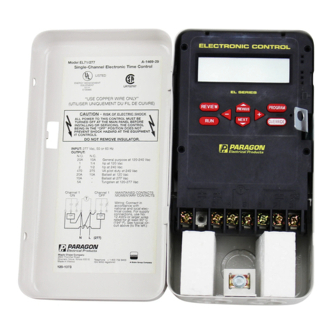
Paragon EL78 Instruction manual

Paragon

Paragon EL78 Instruction manual

Paragon Sentry Xpress 2.0 User manual

Paragon

Paragon Sentry Xpress 2.0 User manual

Paragon EL712 Instruction manual

Paragon

Paragon EL712 Instruction manual

Paragon EC7000 Series Instruction manual

Paragon

Paragon EC7000 Series Instruction manual

Paragon EL7100 Instruction manual

Paragon

Paragon EL7100 Instruction manual

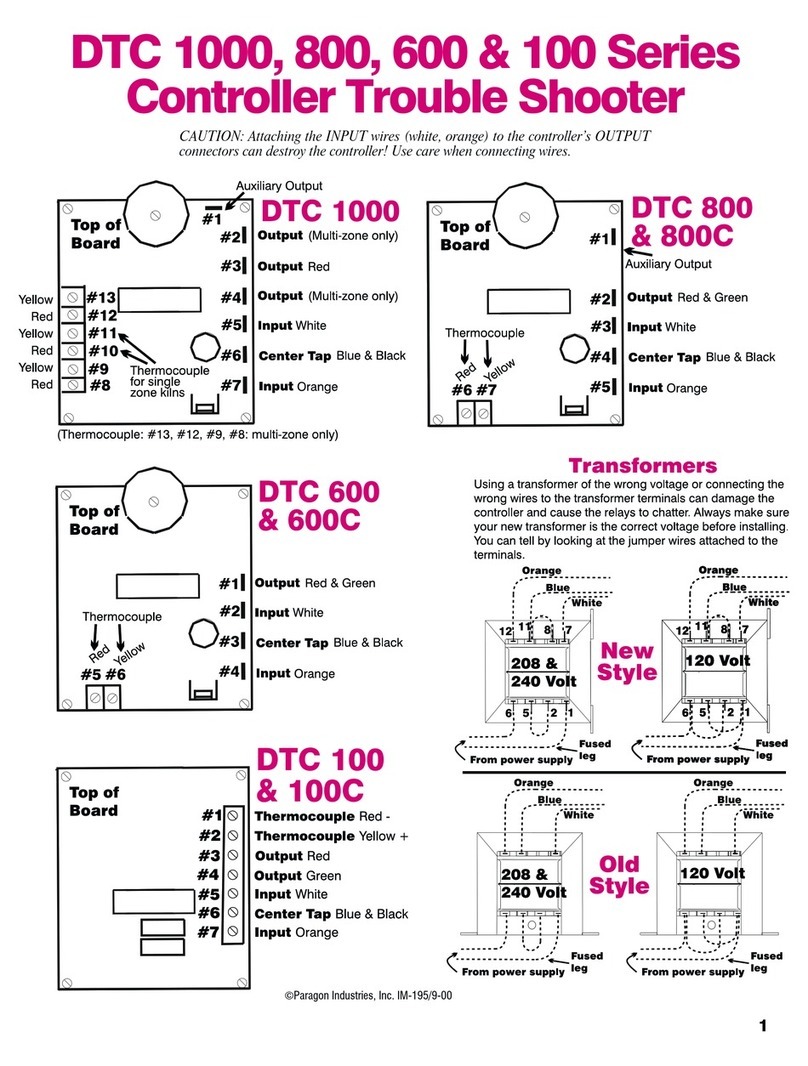
Paragon DTC 1000 series User manual

Paragon

Paragon DTC 1000 series User manual

Paragon DTC 1000 Instruction Manual

Paragon

Paragon DTC 1000 Instruction Manual

Paragon EL71 Instruction manual

Paragon

Paragon EL71 Instruction manual

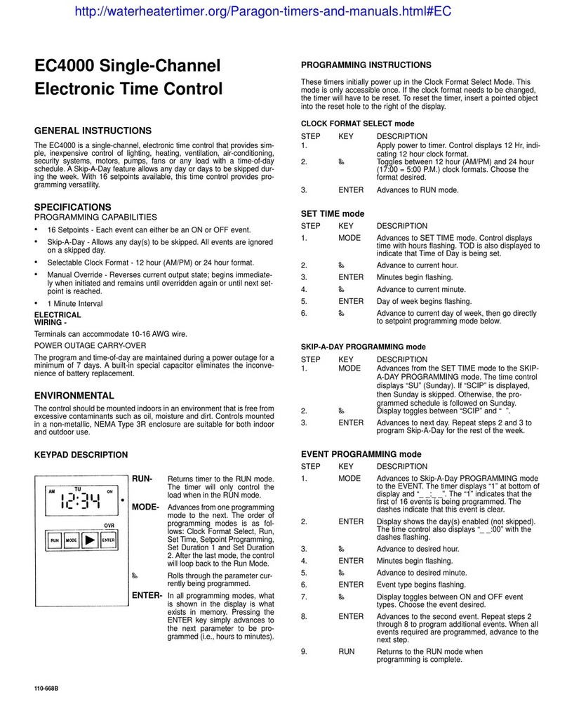
Paragon EC4000 User manual

Paragon

Paragon EC4000 User manual

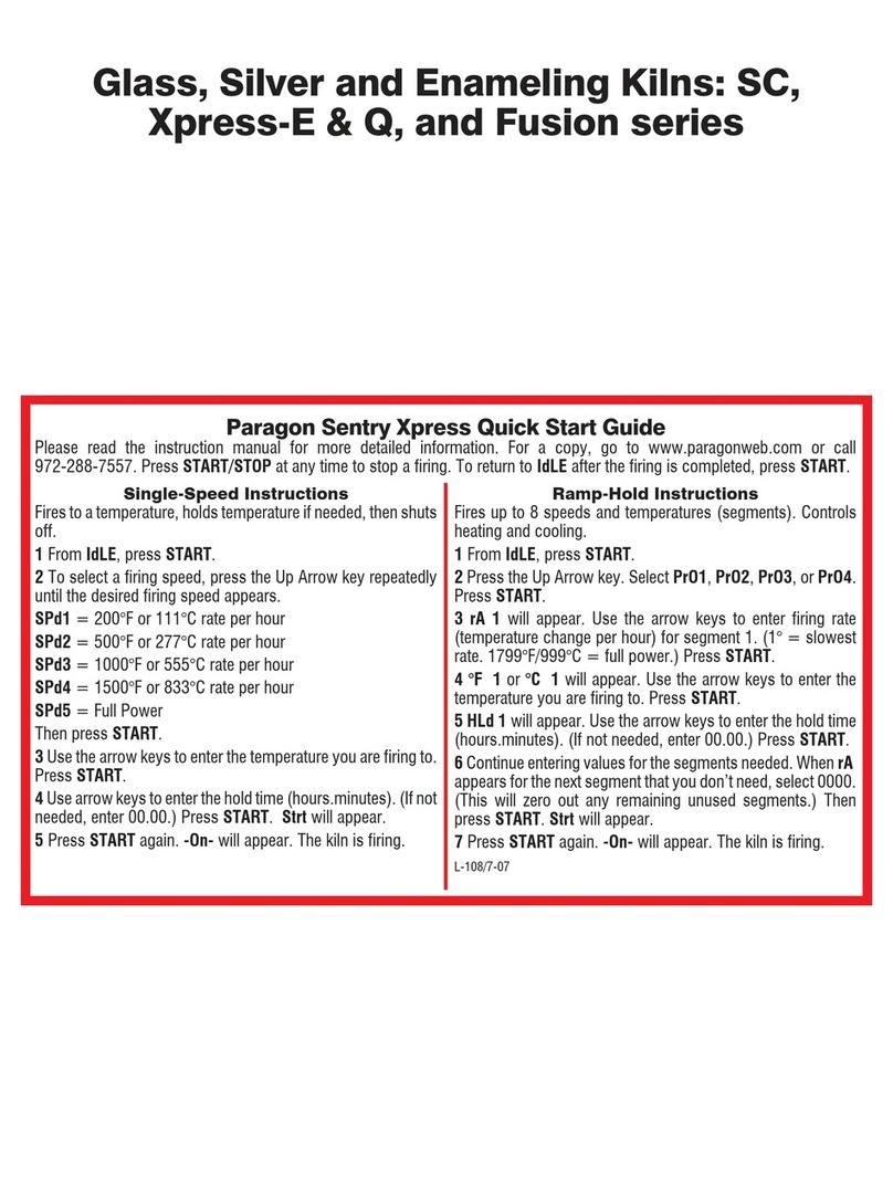
Paragon Sentry Xpress SC Series User manual

Paragon

Paragon Sentry Xpress SC Series User manual

Popular Controllers manuals by other brands

Nvidia BlueField-2 BF2500 Hardware installation

Nvidia

Nvidia BlueField-2 BF2500 Hardware installation

Attainment Company StepPad user guide

Attainment Company

Attainment Company StepPad user guide

Luxul XWC-2000 Quick install guide

Luxul

Luxul XWC-2000 Quick install guide

Tunze 7094 Instructions for use

Tunze

Tunze 7094 Instructions for use

Delta Controls DLC-D312 Installation & Application Guide

Delta Controls

Delta Controls DLC-D312 Installation & Application Guide

Castle Creations Pixie-20P user manual

Castle Creations

Castle Creations Pixie-20P user manual

Unitech UT-102 instruction manual

Unitech

Unitech UT-102 instruction manual

KE2 Therm Solutions Temp + Air Defrost installation manual

KE2 Therm Solutions

KE2 Therm Solutions Temp + Air Defrost installation manual

Honeywell 5 Nm Series Product data

Honeywell

Honeywell 5 Nm Series Product data

YASKAWA Motoman NXC100 manual

YASKAWA

YASKAWA Motoman NXC100 manual

RTI KA8 reference guide

RTI

RTI KA8 reference guide

Active-semi PAC5222EVK1 user guide

Active-semi

Active-semi PAC5222EVK1 user guide

KMC Controls KMD-7001 Installation & operation guide

KMC Controls

KMC Controls KMD-7001 Installation & operation guide

SLV 470700 operating manual

SLV

SLV 470700 operating manual

Juniper WLM1200-RMTS user guide

Juniper

Juniper WLM1200-RMTS user guide

Regulus uREG user manual

Regulus

Regulus uREG user manual

Delta VFD-V Series user manual

Delta

Delta VFD-V Series user manual

AUMA SG Series Operation instructions

AUMA

AUMA SG Series Operation instructions

manuals.online logo
manuals.online logoBrands
  • About & Mission
  • Contact us
  • Privacy Policy
  • Terms and Conditions

Copyright 2025 Manuals.Online. All Rights Reserved.