Eskridge 50L User manual
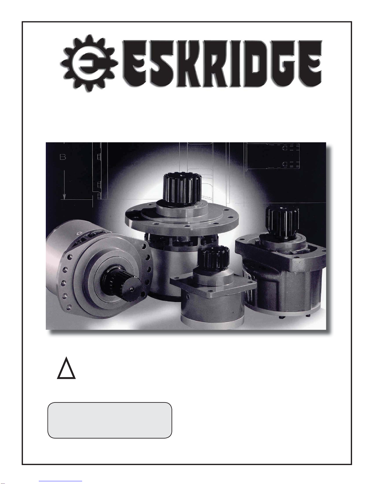
MODEL 50L PLANETARY GEAR
DRIVE SERVICE MANUAL
THIS SERVICE MANUAL IS EFFECTIVE:
S
/N: 38489# TO CURRENT
DATE: 12-16-98 TO CURRENT
VERSION:SM50LD2-AB
!WARNING: While working on this equipment, use safe lifting procedures,
wear adequate clothing and wear hearing, eye and respiratory protection.
NOTE: Individual customer specifications (mounting
case, output shaft, brake assembly, etc.) may vary from
exploded drawing and standard part numbers shown.
If applicable, refer to customer drawing for details.
Model 50 service manual, SM50LD2-AB Page 2
Eskridge, Inc. Olathe, Ks. 913-782-1238 www.eskridgeinc.com
MATCHING
HALVES
2
NOTES:
BEARING PRELOAD DETERMINES QUANTITY OF SHIMS.
30A
30B
(OPTIONAL)
35C
35B
35A
20C
20D
16B
1
20B
20A
16A
2
S2 - SHAFT REQUIRES STUDS (QTY 5) PART NO. 01-164-0040.
FOR GREASE ZERK OPTION, ADD 'Z' SUFFIX TO BASE P/N
(OPTIONAL)
30C
25A
25B
30A
14B
4
5C
5B
5D
5E
5D
5E
14A
5A
5F
12
16B
E.C.N. # 2791
X50LD1-AF 01/15/08
WITH CODE 4
INPUT SPLINE
ONLY
4
35D
14C
ITEMQTY.
85-004-1051
-
DESCRIPTION
RING GEAR
CARRIER
PLANET GEAR
SHIM(S)
SUN GEAR
PLANET SHAFT
CARRIER THRUST WASHER
PLANET THRUST WASHER
BEARING CONE (OUTER)
BEARING CONE (INNER)
BEARING CUP (OUTER)
BEARING CUP (INNER)
PLANET BEARING
INPUT THRUST WASHER
HEX CAPSCREW
ROLL PIN
LOCKWASHER
PIPE PLUG-MAGNETIC
O-RING
SEAL-SHAFT
1
1
3
*
-
3
1
6
1
1
1
1
1
1
6
1
12
3
12
2
2
1
12
3
5A
5B
35A
6
5C
14A
5E
20A
20C
20B
20D
35C
35B
5D
14B
25A
5F
25B
30A
16B
16A
30B
50-004-1033
01-102-0140
01-102-0150
01-103-0130
01-103-0140
01-150-1540
01-166-0340
01-207-0070
01-402-0560
01-405-0530
3/16 X 7/8
7/16 MED
3/8 NPT-SOC HD
11
50-004-3003
50-004-3013
50-004-3193
50-004-1173
50-004-1183
50-004-1233
50-004-1333
12
14
85-004-1382 85-004-1392
85-004-1272 85-004-1262
85-004-1292
85-004-1562 85-004-1572
85-004-1592
COVERS SHAFTS
C
O
D
E
01-215-0010
01-216-0070
(1)
(1)
5:1
5.05 RATIO
PART NUMBER PART NUMBER
BASES
INPUT GEARS
SINGLE PLANETARY
AIR VENT 3/8 NPT (OPTIONAL)
GREASE FITTING (OPTIONAL) STR. 1/8 NPT
MODEL 50L
2
71-004-0121
50-004-1011
85-004-1181
01-105-0010
50-004-1091
01-153-0210
114C
135D
THRUST WASHER
RETAINING RING
4:1
4.08
50-004-1023
85-004-1041
71-004-0121
50-004-1011
85-004-1181
01-105-0010
50-004-1091
01-150-1550
01-153-0210
50-004-1112
5:1
5.05
PART NUMBER
WITHOUT CODE 4
INPUT SPLINE
WITH CODE 4
INPUT SPLINE
81-004-2883
01-160-0350
LOCK RING
50-004-1462
50-004-1452 SPLIT RING (MATCHING HALVES)
50-004-4012L
50-004-4022L
50-004-4032L
50-004-4052L
50-004-4212L
50-004-4082L
50-004-4092L
50-004-4312L
50-004-4292L
50-004-1521
7/16-20 GR8
50-004-4502L
EFFECTIVE
FROM: S/N 16130 07-01-93
TO: (CURRENT)
50-004-1062 50-004-1052 1
CARRIER ASSEMBLY
5
50-005-2041 50-005-2031 1
INPUT GEAR 13T 16/32 DP SPLINE
INPUT GEAR SAE 1"-6B SPLINE
INPUT GEAR14T 12/24 DP SPLINE
INPUT GEAR 15T 16/32 DP SPLINE
INPUT GEAR 1" DIA X .25 KEY
COVER-SAE 'A'
2"DIA SHAFT-3/8" KEYWAY
COVER-SAE 'B' 2-BOLT
23T 12/24 D.P. SPLINE
COVER-SAE 'C' 4-BOLT
COVER-SAE 'C' 2-BOLT
2"DIA X .50" KEY (INTERNAL)
2"DIA SHAFT-1/2" KEYWAY
2"HEX SHAFT-13/16 DIA.HOLE
2"DIA AUGER-.562"HOLE
SHAFT-CUSTOM
A
FLANGLESS (NO ZERK)
7" SPINDLE 50L (5) X 1/2-13
2-1/8"DIA SHAFT-1/2" KEYWAY
7" SPINDLE 50L (5) X .610 DIA THRU HOLES
2-5/8"HEX SHAFT-13/16 DIA.HOLE
CUSTOM
ROUND FLANGE (NO ZERK)
RECTANGULAR FLANGE (NO ZERK)E
F
C
D1
D2
D3
D4
F2
H2
H3
R2
S1
S2
C1
A
B
C
K
2
3
4
5
6
30C
30D
01-207-0030 (1) PIPE PLUG (C & K COVER ONLY) 1/8 NPT
3
SEAL KIT (1 SEAL, 2 O-RINGS)
16
85-016-0601 -
-
X50LD1-AF,
Page 1 of 1
Effective date 7-16-93
Effective serial # 16130
Model 50 service manual, SM50LD2-AB Page 1
Eskridge, Inc. Olathe, Ks. 913-782-1238 www.eskridgeinc.com
MATCHING
HALVES
2
NOTES:
BEARING PRELOAD DETERMINES QUANTITY OF SHIMS.
30A
30B
(OPTIONAL)
35C
35B
35A
20C
20D
16B
1
20B
20A
16A
2
S2 - SHAFT REQUIRES STUDS (QTY 5) PART NO. 01-164-0040.
FOR GREASE ZERK OPTION, ADD 'Z' SUFFIX TO BASE P/N
(OPTIONAL)
30C
25A
25B
30A
14B
4
5C
5B
5D
5E
5D
5E
14A
5A
5F
12
16B
E.C.N. # 2791
X50LD2-AE 01/15/08
ITEMQTY.
50-004-1082
85-004-1051
85-004-1031
DESCRIPTION
RING GEAR
CARRIER
PLANET GEAR
PLANET GEAR
SHIM(S)
SUN GEAR
PLANET SHAFT
PLANET SHAFT
CARRIER THRUST WASHER
PLANET THRUST WASHER
PLANET THRUST WASHER
BEARING CONE (OUTER)
BEARING CONE (INNER)
BEARING CUP (OUTER)
BEARING CUP (INNER)
PLANET BEARING
PLANET BEARING
INPUT THRUST WASHER
HEX CAPSCREW
ROLL PIN
ROLL PIN
LOCKWASHER
PIPE PLUG-MAGNETIC
O-RING
SEAL-SHAFT
1
1
3
*
-
3
1
6
1
1
1
1
1
1
1
12
3
12
2
2
1
12
3
5A
7B
5B
35A
6
7C
5C
14A
7E
5E
20A
20C
20B
20D
35C
35B
7D
5D
14B
25A
7F
5F
25B
30A
16B
16A
30B
30C
50-004-1023
81-004-1561
01-102-0140
01-102-0150
01-103-0130
01-103-0140
01-150-1550
01-153-0080
01-166-0340
01-207-0070
01-402-0560
01-405-0530
3/16 X 7/8
1/8 X 1
7/16 MED
3/8 NPT-SOC HD
01-105-0410
1 1
50-004-3003
50-004-3013
50-004-3193
50-004-1173
50-004-1183
50-004-1233
50-004-1333
12
14
85-004-1102 85-004-1062
85-004-1122 85-004-1112
85-004-1533
85-004-1542 85-004-1422
85-004-1582
COVERS SHAFTS
C
O
D
E
INPUT GEAR 13T 16/32 DP SPLINE
INPUT GEAR SAE 1"-6B SPLINE
INPUT GEAR 14T 12/24 DP SPLINE
INPUT GEAR 15T 16/32 DP SPLINE
INPUT GEAR 1" DIA X .25 KEY
COVER-SAE 'A'
2"DIA SHAFT-3/8" KEYWAY
COVER-SAE 'B' 2-BOLT
23T 12/24 D.P. SPLINE
COVER-SAE 'C' 4-BOLT
COVER-SAE 'C' 2-BOLT
2"DIA X .50" KEY (INTERNAL)
2"DIA SHAFT-1/2" KEYWAY
2"HEX SHAFT-13/16 DIA.HOLE
SHAFT-CUSTOM
01-215-0010
01-216-0070
(1)
(1)
RATIO
PART NUMBER PART NUMBER
BASES
INPUT GEARS
AIR VENT 3/8 NPT (OPTIONAL)
GREASE FITTING (OPTIONAL) STR. 1/8 NPT
MODEL 50L
A
FLANGLESS (NO ZERK)
2
81-004-0071
50-004-1072
85-004-1041
85-004-1021
71-004-0121
50-004-1011
85-004-1181
01-105-0010
50-004-1091
01-153-0210
PART NUMBER
LOCK RING
50-004-1462
50-004-1452 SPLIT RING (MATCHING HALVES)
7" SPINDLE 50L (5) X 1/2-13
50-004-4012L
50-004-4022L
50-004-4032L
50-004-4052L
50-004-4212L
50-004-4082L
50-004-4312L
50-004-4292L
50-004-1521
7/16-20 GR8
2-1/8"DIA SHAFT-1/2" KEYWAY
7" SPINDLE 50L (5) X .610 DIA THRU HOLES
2-5/8"HEX SHAFT-13/16 DIA.HOLE
50-004-4502L
CARRIER7A
50-004-1062
1
CARRIER ASSEMBLY5
CARRIER ASSEMBLY7
50-005-2041
1
25.53:1
5.05
5.05
20.62:1
4.08
5.05
INVERTED
1
16.65:1
4.08
4.08
20.62:1
5.05
4.08
PART NUMBER
50-004-1082
85-004-1031
50-004-1052
50-005-2031
50-005-2011 50-005-2021 50-005-2011
85-004-1072
85-004-1412 85-004-1092
INVERTED RATIO SUNGEAR IS NOT COUNTERBORED FOR CODE 4 INPUT. MOTOR COMPATIBILITY MUST BE VERIFIED.
1
6
7B
7D
7E
7E
7C
7A
7F
EFFECTIVE
FROM: S/N 38000 11-01-98
TO: (CURRENT)
DOUBLE PLANETARY
CUSTOM
ROUND FLANGE (NO ZERK)
RECTANGULAR FLANGE (NO ZERK)
E
F
C
D1
D2
D3
D4
F2
H2
H3
S1
S2
C1
A
B
C
K
2
3
4
5
6
30D01-207-0030 (1) PIPE PLUG (C & K COVER ONLY) 1/8 NPT
3
3
6
6
3
1
1
3
3
-
-
85-004-1533
-
85-004-1582
SEAL KIT (1 SEAL, 2 O-RINGS)
-1685-016-0601
X50LD2-AE,
Page 1 of 1
Effective date 12-16-98
Effective serial # 38489
Model 50 service manual, SM50LD2-AB Page 2
Eskridge, Inc. Olathe, Ks. 913-782-1238 www.eskridgeinc.com
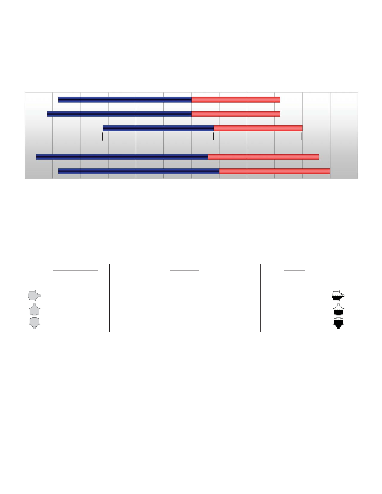
LUBRICATION & MAINTENANCE
Operating Position
Single stage
Oil Capacity
Double stage Triple stage
Oil Level
Horizontal Shaft 1.4 pt / 0.7 l 1.6 pt / 0.8 l 1.8 pt / 0.9 l To horizontal centerline of
gear drive
Vertical Shaft (Pinion Up) 1.7pt / 0.8 l 2.2 pt /1.0 l 2.7 pt /1.3 l To side port on gear drive
base
Vertical Shaft (Pinion Down) 2.2pt / 1.0 l 2.7 pt /1.3 l 3.2 pt /1.6 l To midway on upper/
primary gear set
Using the chart below, determine an appropriate lubricant viscosity. Use only EP (extreme pressure) or API GL-5 designated lubricants.
Change the lubricant after the first 50 hours of operation and at 500 hour intervals thereafter. The gear drive should be partially disas-
sembled to inspect gears and bearings at 1000 hour intervals.
80W90 conventional
75W90 conventional
85W140 conventional
75W90 synthetic
80W140 synthetic
Note: Ambient temperature is the air temperature measured in the immediate vicintiy of the gearbox. A Gearbox exposed to the direct rays of
the sun or other radiant heat sources will operate at higher temperatures and therefore must be given special consideration. The max operating
temp must not be exceeded under any circumstances, regardless of ambient temperature.
If your unit was specified “shaft up” or with a “-Z” option, a grease zerk was provided in the base housing. For shaft-up operation, the
output bearing will not run in oil and must be grease lubricated. Use a lithium based or general purpose bearing grease sparingly every
50 operating hours or at regular maintenance intervals. Over-greasing the output bearing should be avoided as it tends to fill the housing
with grease and thicken the oil
Recommended ambient and operating temperatures for conventional and synthetic gear lubricants
-50 -25 0 25 50 75 100 125 150 175 200 225 250 F
-45 -32 -18 -4 10 24 38 52 66 79 93 107 121 C
Min Ambient/operating temp Max Operating temp
Max Ambient temp
ESKRIDGE MODEL 50 OIL CAPACITIES
ESKRIDGE PART NUMBER INTERPRETATION
Note:All non-custom Eskridge Geardrives are issued a descriptive part number which includes information regard-
ing the Model, means of shaft retention, base style, shaft style, input mounting, input shaft size, overall ratio and
various available options. For a detailed breakdown of this information, please refer to Eskridge product specifica-
tion sheets found at: http://www.eskridgeinc.com/geardrives/gearprodspecs.html

Model 50 service manual, SM50LD2-AB Page 3
Eskridge, Inc. Olathe, Ks. 913-782-1238 www.eskridgeinc.com
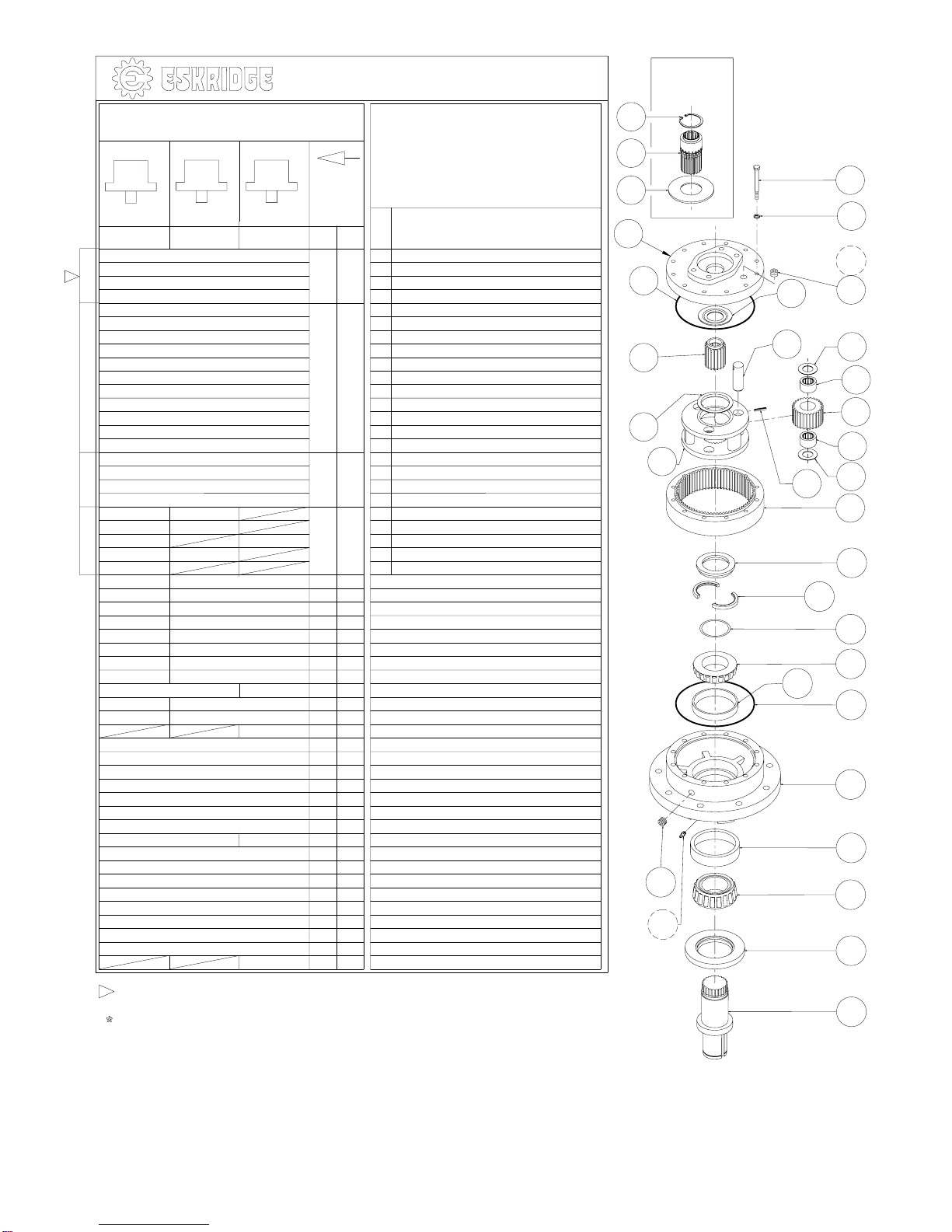
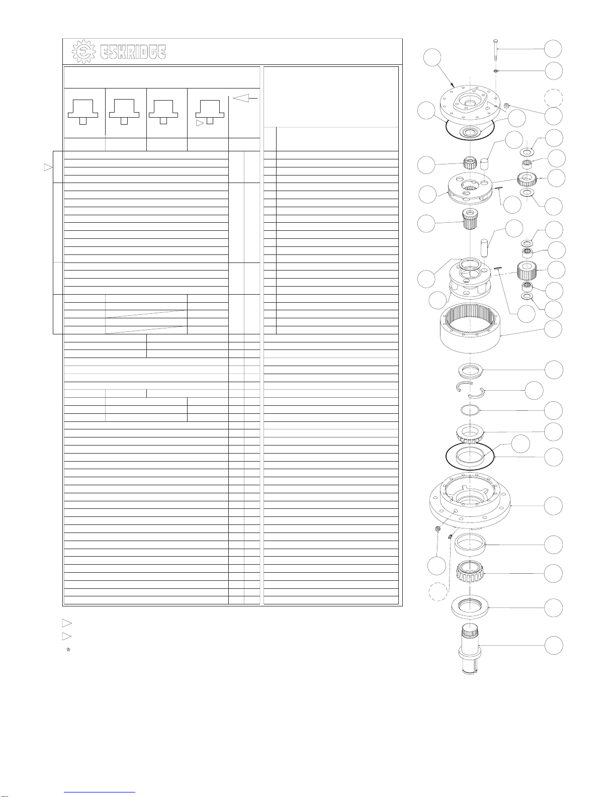
Unit Teardown
1) Scribe a diagonal line across the outside of the unit from the
cover (3) to the base (1) before disassembly to aid in the proper
positioning of pieces during reassembly.
2) Remove drain plugs (30A) and drain oil from unit. The oil will
drain out more quickly and completely if warm.
3) Remove the 12 7/16-20 capscrews (25A) and lockwashers
(25B) securing the cover.
4) Remove the cover (3), thrust washer (14B), and input gear (4).
Inspect o-ring (16B); discard if damaged or deformed.
5) Lift the planet carrier assembly out of the unit .
6) Remove ring gear(s) (12) and subsequent carrier assemblies
and thrustwasher (14A). Inspect gear to gear and gear to base
O-ring(s) (16B); as before, discard if damaged or deformed.
7) The unit is now disassembled into groups of parts. the area(s)
requiring repair should be identified by thorough inspection of
the individual components after they have been cleaned and
dried.
Carrier Assembly Teardown
Rotate planet gears (7B pri/5B sec) to check for abnormal
noise or roughness in bearings (7D pri/5D sec). If further in-
spection or replacement is required, proceed as follows.
1) Drive roll pins (7F pri/5F sec) completely into the planet shafts
(7C pri/5C sec).
2) Slide planet shafts (7C pri/5C sec) out of carrier (7A pri/5A
sec).
3) Remove planet gears (7B pri/5B sec), washers (7E pri/5E
sec) and bearings (7D pri/5D sec) from carrier (7A/5A).
4) Inspect the planet gear (7B pri/5B sec), bearing bore and plan-
et shaft (7C pri/5C sec) and bearings (7D pri/5D sec). Check
for spalling, bruising or other damage and replace components
as necessary.
5) Remove roll pins (7F pri/5F sec) from planet shafts (7C pri/5C
sec) using a 1/8” (pri) or 3/16” (sec) pin punch.
Carrier Reassembly
1) Planet shafts (7C pri/5C sec) should be installed with cham-
fered end of 1/8”(pri), or 3/16”(sec) roll pin hole towards outside
diameter of carrier (7A pri/5A sec); this will ease alignment of
holes while inserting roll pins (7F pri/5F sec).
2) Drive roll pin (7F pri/5F sec) into the carrier hole and into plan-
et shaft to retain parts. Repeat for remaining planet gears.
Base Subassembly Teardown
1) Remove the shaft retainer lock ring (35C) using a heel bar or
puller; if using a heel bar, be sure not to pry against the cage
of the inner output shaft bearing (20C). Remove the split ring
segments (35B) and shims (35A).
Caution: Since the shaft is no longer positively retained,
care should be taken to avoid personal injury. Care should
also be taken not to damage it while pressing through
base.
Note: Removing the shaft from the base assembly damages
the shaft seal. The seal will need to be replaced.
2) Place base (1) external side down, supported at the case
perimeter. Press output shaft out bottom of base by apply-
ing a load to internal end of shaft until it passes through
inner shaft bearing cone (20C).
3) A gear puller may be used to remove the outer bearing
cone (20A) from the shaft (2). If reusing old bearing cone,
donotpullonordamagerollercage.If shaft bearings show
evidence of wear or damage they should be replaced at
this time. Remove the shaft seal (16A) for inspection or
replacement.
Note: When installing new shaft bearings. press the bearing
cone onto output shaft by pressing on inner race only. DO
NOT press on roller cage, as it will damage the bearing.
4) Lubricate inner lip of new shaft seal (16A) and slide it onto
the shaft (2) until it fits snugly over the shaft seal diameter
with the open side toward the interior of the gear drive.
5) Inspect inner and outer bearing cups (20D & 20B). If cups
are damaged, drive them out using a brass drift and utiliz-
ing the bearing knock-out notches in the base (1)
Base Reassembly
1) Clean all foreign material from any magnetic oil plugs lo-
cated on base (1).
2) Place base exterior side up on work table.
3) Apply a layer of lithium or general purpose bearing grease
to the roller contact surface of outer bearing cup (20B).
4) Press outer bearing cone (20A) onto the shaft until it seats
against the shoulder.
5) Place the shaft (2) with the bearing cone (20A) into the
base.
6) Flip shaft/base assembly, and apply lithium or general pur-
pose bearing grease to roller contact surface of the inner
cup (20D), then press inner bearing cone (20C) onto shaft
until it seats against inner bearing cup (20D).
7) Prior to installation of the shaft seal (16A), the pre-
load may result in a rolling torque which varies be-
tween 50 to 80 in-lb. The bearing preload should be
tailored to your application; a low-speed application may
require a high pre-load, while high-speed applications
usually benefit from low pre-load. Adding shims (35A) will
increase the pre-load on the bearing set. Determine your
pre-load requirement and install shims to obtain this pre-
load.
8) Install the Load-N-Lock™ segments (35B) over the shims

Model 50 service manual, SM50LD2-AB Page 4
Eskridge, Inc. Olathe, Ks. 913-782-1238 www.eskridgeinc.com
(35A) and into the groove in the shaft (2). Then, install the lock
ring (35C) over the segments (35B).
All subassembly service or repairs should be complete at this
time. Continue to Unit Reassembly to complete unit buildup..
Unit Reassembly
1) Install the secondary carrier assembly (5) onto the output shaft
(2); align the splines of the carrier (5A) with the output shaft (2)
splines and slide the carrier onto the shaft.
2) Lubricate o-rings (16B) and install into the corresponding base
(1) and cover (3) pilot(s).
Caution: Hold ring gear(s) by outside diameter or use lifting de-
vice to avoid injury.
3) Aligngearteethoftheringgear(12)withthegearteethoftheplan-
etgears(5B)andplaceonbase(1),thenalignmountingholesof
ring gear (12) with holes in base (1). Use the scribed line made
during disassembly for reference.
4) Install the carrier thrust washer (14A) and sun gear (6) into the
secondary carrier (5A).
5) Install the primary carrier assembly (7).
6) Install the input gear (4).
7) Install the input thrust washer (14B) Refer to exploded view for
details.
8) Noting the scribed line made during disassembly, (with lubri-
cated o-ring in place) align and install the cover (3).
9) Install and torque the 12 7/16-20 hex-head cap-screws (25A)
with lockwashers (25B). The torque for the cap-screws: 80 ft-lb
dry, 60 ft-lb if lubricated.
10) Using a splined shaft to drive the input gear (4) ensure that the
unit spins freely.
11) Fill the unit to the proper level, as specified, with recommended
gear oil (refer to chart, page 2) after unit is sealed with brake
and/or motor.
The gearbox is now ready to use.
Table of contents
Other Eskridge DC Drive manuals


Popular DC Drive manuals by other brands

Rockwell Automation
Rockwell Automation Allen-Bradley PowerFlex 7000 user manual

Nidec
Nidec DFS Series Power Installation Guide

StepperOnline
StepperOnline DM556T user manual

Smartrise
Smartrise HPV900 Startup manual

GFA
GFA ELEKTROMAT SE 9.15 WS-25,40 installation instructions

Knauer
Knauer Azura V 2.1S user manual


