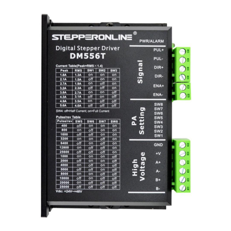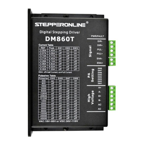
DM556T Digital Stepper Drive User Manual
Table of Contents
1. Features ........................................................................................................................................................................... 1
2. Specifications .................................................................................................................................................................. 1
2.1 Electrical Specifications .........................................................................................................................................1
2.2 Environment ...........................................................................................................................................................1
2.3 Mechanical Specifications ..................................................................................................................................... 1
2.4 Elimination of Heat ................................................................................................................................................2
3. Connection Pin Assignments and LED Indication ..................................................................................................... 2
3.1 Control Connector ..................................................................................................................................................2
3.2 Fault Output Connector ..........................................................................................................................................3
3.3 Motor and Power Supply Connector ..................................................................................................................... 3
3.4 LED Light Indication ............................................................................................................................................. 3
4. Control Signal and Output Signal ................................................................................................................................3
4.1 Control Signal Connection .....................................................................................................................................3
4.2 Fault Output Connection ........................................................................................................................................3
5. Motor Connection .......................................................................................................................................................... 4
6. Power Supply Selection ................................................................................................................................................. 4
6.1 Power Supply Sharing ............................................................................................................................................4
6.2 Selecting Supply Voltage ....................................................................................................................................... 5
7. DIP Switch Configurations ............................................................................................................................................5
7.1 Microstep Resolution Configurations ....................................................................................................................5
7.2 Output Current Configurations .............................................................................................................................. 5
7.2.1 Dynamic Current Configurations ............................................................................................................... 6
7.2.2 Idle Current Configuration ..........................................................................................................................6
8. Wiring Notes ................................................................................................................................................................... 6
9. Typical Connection .........................................................................................................................................................6
10. Sequence Chart of Control Signals ............................................................................................................................ 7
11. Protection Functions .................................................................................................................................................... 7
12. Troubleshooting ............................................................................................................................................................8


