perating manual
solar battery station 12 V/ 24 Ah
These instructions relate NLY to this product and contain important
information for using the product for the first time. Please keep these
instructions for later reference and should always accompany the pro-
duct in the event of transference to a new user.
1. Introduction
Dear Costumer, thank you for purchasing the solar pump kit.
With this solar pump kit you purchased a product manufactured according to the
current state of technology.
This product fulfils all requirements of the valid European and national
regulations. The conformity was proved. The relevant declarations and
documentation are deposited with the manufacturer.
To maintain this state and guarantee a safe operation, you as the user will have
to follow this operating manual!
2. Safety Instructions
- In case of damages caused by not following
this operating manual, the warranty rights
will expire! We exclude liability for any
consequential damages!
- We exclude liability for property or
personal damages caused by inappropriate
handling or not following the safety instructions.
- In these cases any guarantee rights will expire.
Due to safety and admission reasons (CE) it is not allowed to arbitrarily recon-
struct and/or change the solar pump kit.
Therefore, please keep to the operating manual.
The accident prevention rules of the association of the industrial trade coopera-
tive association for electric plants and working material are to be considered in
industrial environments
3. Intended Use
- The accumulator station can be universally used in order to supply the
pumps Rimini, Palermo, Verona, Toscana, apoli, Siena, Garda, the air
pump Solar Air or other 12 Volt devices (e.g. illumination, radio, etc.) with
energy.
- The accumulator station has 4 switchable outputs with different voltages.
- Via controller, the output 4 may be adjusted between 12 and 18 V. It is pos-
sible to activate a timer function.
- The accumulator station may be switched on or off via a switch. However,
the charging is continued.
- The integrated accumulator is protected against deep discharge, overchar-
ging and short circuit.
- LEDs inform the user about the state of charge and charging of the accumu-
lator as well as the status of the outputs.
- The system is plug-in-ready and set up within minutes.
Note: The accumulator station must not be set up in the blazing sun or in the
water. It is constructed in IP 44 (splashproof).
Mode of operation:
The accumulator station is interconnected between the solar module(s) and the
corresponding devices.
With solar radiation, the solar module generates electric energy and charges the
installed accumulator. The connected consumers are switched on if the accu-
mulator voltage is within its operative range. The LED „SYSTEM“ will inform
the user about the state of charge of the accumulator.
The electronics protects the accumulator against deep discharge, overcharging
or short circuit.
The charging of the accumulator has always priority over the operation of
the consumers.
4. Assembly/installation and start of operation
4.1 Connection of the solar module
A maximum power of the solar module of 50
Wp may be connected to the accumulator box.
The module has to be connected to the socket
„I PUT DC 18V“ on the back side of the accu-
mulator box.
Depending on the type/version, you will have one or two solar module(s) with
the matching plug in the set. One solar module may directly be connected to the
accumulator box. If you have two solar modules (e.g. each 25 Wp), it is requi-
red to use an Y-manifold.
Included in the delivery is a 5 m extension cable. If required, it is possible to con-
nect another 5 m extension cable (esotec Art.- o: 101736).
As soon as the solar module is connected and the solar module is exposed to
sunlight, the LED „Charging“ will be illuminated. The accumulator is fully char-
ged if the LED is flashing.
Please note that the solar modules have to be set up in a shadow-free place ori-
ented towards the south and that they have to be mounted stably.
The cap nut of the plugs has to be screwed tightly.
Attention: The electronics in the accumulator box will be destroyed if a solar
module power of more than 50 W is connected!
4.2 Main switch „SYSTEM“
The toggle switch „SYSTEM N/ FF“ is
mounted on the back side of the accumulator
box. If this switch is switched off, then the out-
puts are deactivated. However, the charging of
the accumulator is continued.
In position „O “, the LED „SYSTEM“ will be
illuminated red or green.
A green LED means that the accumulator is sufficiently charged and the outputs
may, as required, be operated via the buttons on the lid of the box.
A red LED means that the outputs are deactivated (switched off) and that the
accumulator has to be charged until the LED is illuminated in green.
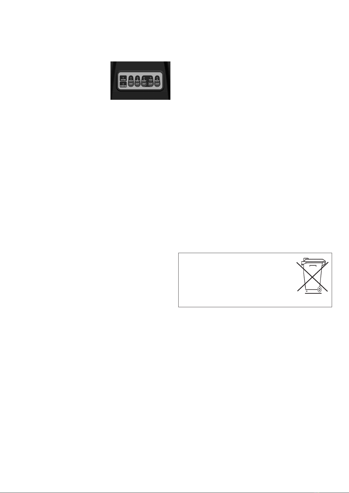
4.3 Connection of the consumers
The accumulator box has 4 outputs. Those outputs may be switched on or off
via the „ N/ FF“ buttons. The green LED above the button will be illuminated
in green if the output is active.
All outputs are protected against short cir-
cuit. In case of a short circuit, the correspon-
ding green LED of the output will flash until
the short circuit is eliminated.
Below, every output will be described indivi-
dually. All outputs are equipped with a pro-
tective cap. Those caps have to be removed
before you connect anything.
- utput 1:
utput voltage: 6 VDC, max. current load: 1 A
For the connection of esotec pump „Rimini“ (Art.- o.: 101750), esotec pump
„Palermo“ (Art.- o.: 101756) or pond aerator „Solar Air-S“ (Art.- o.:
101871).
- utput 2:
utput voltage: 12 VDC, max. current load: 1 A
For the connection of esotec pump „ apoli“ (Art.- o.: 101757), esotec pump
„Siena“ (Art.- o.: 101758), esotec pump „Verona“ (Art.- o.: 101752) or eso-
tec pump „Toscana“ (Art.- o.: 101754).
- utput 3:
utput voltage: 12-18 VDC, max. current load: 1 A
For the connection of esotec watercourse pump „Garda“ (Art.- o.: 101760).
The output voltage may be adjusted between 12 V and 18 V by means of
the control dial.
The timer operation is activated by pressing the button „Timer“. That means
that every hour the output „ UTPUT 3“ is each activated for approx. 10
minutes. This operation mode is particularly useful in case of insufficient
solar radiation.
- utput 4:
utput voltage: 12 VDC, max. current
load: 4 A
For the connection of various consumers
such as e.g. LED lamps, radio, etc. Those
devices are connected by means of screw-
type terminals on the back side of the box.
!
GB
Customer support:
If you have problems or questions regarding this product, simply contact us!
Monday to Friday 8 am to 12 noon and 1 pm to 4 pm.
By phone: +49 9605-92206-0
Product: Manufacturer Item No.: 101729