Espedeo DAC Series User manual

DAC Series
Digital-to-Analog Audio Converter
(Model: DAC-2808 · DAC-2812 · DAC-2816 · DAC-2824 · DAC-2832)
User Manual
Before installing and operating the DAC Series Digital-to-Analog Audio Converter, please read this User Manual thoroughly

-2 -
Table of Contents
1. Introduction....................................................................................................................3
2. Dimensions ....................................................................................................................4
3. Technical Specifications...............................................................................................5
4. Packing List ...................................................................................................................6
5. Safety Instructions ........................................................................................................7
6. Regulatory Information .................................................................................................9
7. AES3 / Analog Output Connection.............................................................................10
8. Routing Diagram..........................................................................................................11
9. Installation and Panel Description.............................................................................13
9.1 Installation..................................................................................................................13
9.2 AC Mains Supply .......................................................................................................13
9.3 Front Panel of DAC Series ........................................................................................14
9.4 Rear Panel of DAC Series .........................................................................................15

-3 -
1. Introduction
The Espedeo™DAC Series offers five Digital-to-Analog Audio Converters models [DAC-28xx, where ‘xx’
represents the number of analog output channels, that is 08 /12 /16 /24 /32] designed to interface with the
GDC SR-1000 Integrated Media Block™and the Espedeo Supra-5000 RGB+ Laser Phosphor Cinema
Projector. Each model supports the specified number of AES3 digital audio inputs through RJ-45 socket(s)
and the outputs are accessible via Phoenix connectors.
The Espedeo DAC Series’ front panel LED indicators show signal presence on each AES3 pair, providing an
audio interface solution for your entertainment needs.
For details regarding the usage of the DAC Series Digital-to-Analog Audio Converter with the GDC SR-1000 or
the Espedeo Supra-5000, please refer to the product documentation on the GDC or Espedeo website.
-4 -
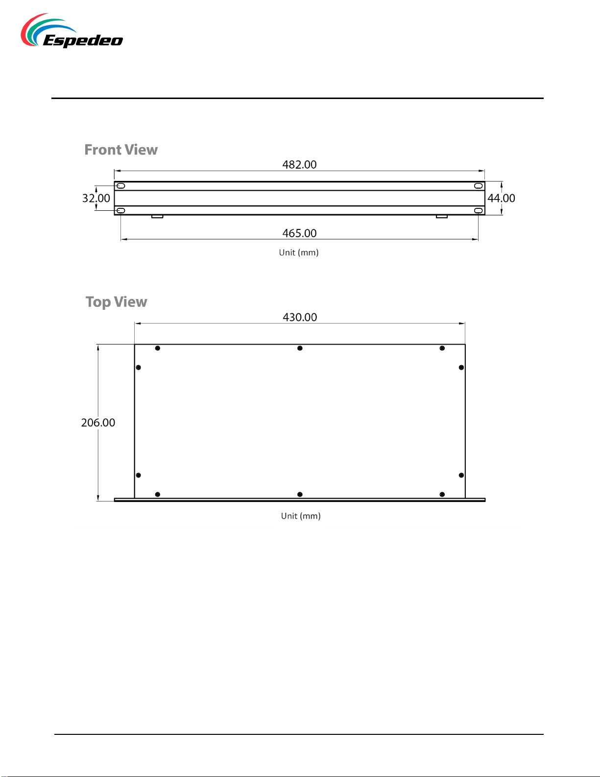
2. Dimensions
Figure 1: DAC Series Dimensions (in mm)
-5 -
3. Technical Specifications
Model →
DAC-2808
DAC-2812
DAC-2816
DAC-2824
DAC-2832
Frequency Range
20 Hz –20,000 Hz
AES3 Input
1 x RJ-45
2 x RJ-45
2 x RJ-45
3 x RJ-45
4 x RJ-45
Max. AES3 Input Pairs
4
6
8
12
16
Analog Balanced Output
8 x
3 pin Phoenix
12 x
3 pin Phoenix
16 x
3 pin Phoenix
24 x
3 pin Phoenix
32 x
3 pin Phoenix
LED Indicators
AES3 signal presence
Input Sample Rate
32 –192KHz
Power Rating
AC 100V –240V 1.0A Max. 50/60Hz
Max. Power Consumption
15W
Power Cable
1.5m mains cable
(EU: Type F –C13 or US: Type B –C13 or
UK: Type G –C13 or CN: Type I –C13 or IN: Type M –C13)
Rack Height
1U
Product Dimensions
(WxHxD)
482 x 44 x 206 mm
Package Dimensions
(WxHxD)
530 x 110 x 330 mm
Product Weight
2.4kg
2.5kg
2.6kg
2.7kg
2.8kg
Package Weight
3.3kg
3.4kg
3.5kg
3.6kg
3.7kg
Table 1

-6 -
4. Packing List
The DAC Series Digital-to-Analog Audio Converter package consists of the components listed under Table 2.
Sr. No.
Part Description
Quantity
①
DAC 28xx Digital-to-Analog Audio Converter Unit
1 PCS.
②
Analog Output Terminal
Model: DAC-2808
8 PCS.
Model: DAC-2812
12 PCS.
Model: DAC-2816
16 PCS.
Model: DAC-2824
24 PCS.
Model: DAC-2832
32 PCS.
③
Power Cable#
1 PCS.
# The required plug type for the power cord can be specified as per regional requirements.
Table 2
NOTE:Please retain the original packaging of the DAC for RMA shipments. The transport and protective packing
have been selected from materials that are environmentally friendly, which can normally be recycled.
-7 -
5. Safety Instructions
Explanation of Graphical Symbols:
The triangle with the lightning bolt is used to alert the user to the risk of electric shock.
The triangle with the exclamation point is used to alert the user to important operating or
maintenance instructions.
The CE-mark indicates compliance with low voltage and electromagnetic compatibility.
Symbol for earth/ground connection.
Symbol indicating that the equipment is for indoor use only.
Symbol for conformity with Directive 2002/96/EC and Directive 2003/108/EC of the European
Parliament on waste electrical and electronic equipment (WEEE).
WARNING: TO REDUCE THE RISK OF ELECTRIC SHOCK, DO NOT ATTEMPT TO OPEN
ANY PART OF THE UNIT. NO USER-SERVICEABLE PARTS INSIDE. REFER SERVICING
TO QUALIFIED SERVICE PERSONNEL.
TO COMPLETELY DISCONNECT THIS APPARATUS FROM THE AC MAINS,
DISCONNECT THE POWER SUPPLY CORD PLUG FROM THE AC RECEPTACLE.
THE MAINS PLUG OF THE POWER SUPPLY CORD MUST REMAIN READILY ACCESSIBLE.
DO NOT EXPOSE THIS EQUIPMENT TO RAIN OR MOISTURE, DRIPPING OR
SPLASHING LIQUIDS. OBJECTS FILLED WITH LIQUIDS, SUCH AS VASES, SHOULD
NOT BE PLACED ON THIS APPARATUS.
WHEN THE UNIT IS INSTALLED IN RACK CABINET OR A SHEFL, MAKE SURE THAT IT
HAS SUFFICIENT SPACE ON ALL SIDES TO ALLOW FOR PROPER VENTILATION (50
CM FROM THE FRONT AND REAR VENTILATION OPENINGS).
CONNECTIONS TO THE MAINS SHALL BE DONE ONLY BY AN ELECTROTECHNICALLY
SKILLED PERSON ACCORDING TO THE NATIONAL REQUIREMENTS OF THE
COUNTRIES WHERE THE UNIT IS SOLD.

-8 -
IMPORTANT SAFETY INSTRUCTIONS
1. Read these instructions carefully.
2. Do not use this equipment near water.
3. Clean only with a dry cloth.
4. Do not block any ventilation openings. Install in accordance with the
manufacturer’s instructions.
5. Do not use near heat sources such as stoves, heat registers, radiators or other equipment
(including amplifiers) that produces heat.
6. Do not use the unit near open fire sources.
7. Connect the unit only to the electric network with grounding. Use only electric plugs that
provide grounding.
8. Protect the power cord from being walked on, pinched or otherwise damaged.
9. Use only accessories specified by the manufacturer.
10. Unplug this unit during lightning storms or when unused for long periods.
11. Refer all servicing to qualified service personnel. Servicing is required when the system has been
damaged in any way, such as power supply cord or plug is damaged, liquid has been spilled or
objects have fallen into the unit, the unit has been exposed to rain or moisture, does not operate
normally or has been dropped.
12. WARNING - TO REDUCE THE RISK OF FIRE OR ELECTRIC SHOCK, DO NOT EXPOSE THIS
SYSTEM UNIT TO RAIN OR MOISTURE.
THIS UNIT CONTAINS POTENTIALLY LETHAL VOLTAGES. TO PREVENT ELECTRIC SHOCK
OR HAZARD, DO NOT REMOVE THE COVER. NO USER-SERVICEABLE PARTS INSIDE.
REFER SERVICING TO QUALIFIED SERVICE PERSONNEL.
INSTALLING OF THIS UNIT MUST BE PERFORMED ONLY BY QUALIFIED TRAINED PERSONNEL
FOLLOWING APPLICABLE SAFETY RULES. DO NOT ALLOW INSTALLING OF THIS UNIT IF
INSTALLATION HARDWARE IS BROKEN, BENT, PARTS ARE MISSING OR IS OTHERWISE DAMAGED.

-9 -
6. Regulatory Information
FCC COMPLIANCE STATEMENT
This device complies with Part 15 of the FCC rules. Operation is subject to the following two conditions:
(1) This device may not cause harmful interference and (2) this device must accept any interference received,
including interference that may cause undesired operation.
CAUTION: Changes or modifications not expressly approved by the party responsible for compliance could void
the user’s authority to operate the equipment.
NOTE:This equipment has been tested and found to comply with the limits for a Class B digital device, pursuant to
Part 15 of the FCC Rules. These limits are designed to provide reasonable protection against harmful interference
in a residential installation. This equipment generates, uses and can radiate radio frequency energy and, if not
installed and used in accordance with the instruction manual, may cause harmful interference to radio
communications. However, there is no guarantee that interference will not occur in a particular installation. If this
equipment does cause harmful interference to radio or television reception, which can be determined by turning
the equipment off and on, the user is encouraged to try to correct the interference by one or more of the following
measures:
▪Reorient or relocate the receiving antenna.
▪Increase the separation between the equipment and receiver.
▪Connect the equipment into an outlet on a circuit different from that to which the receiver is connected.
▪Consult the dealer or an experienced radio/TV technician for help.
-10 -
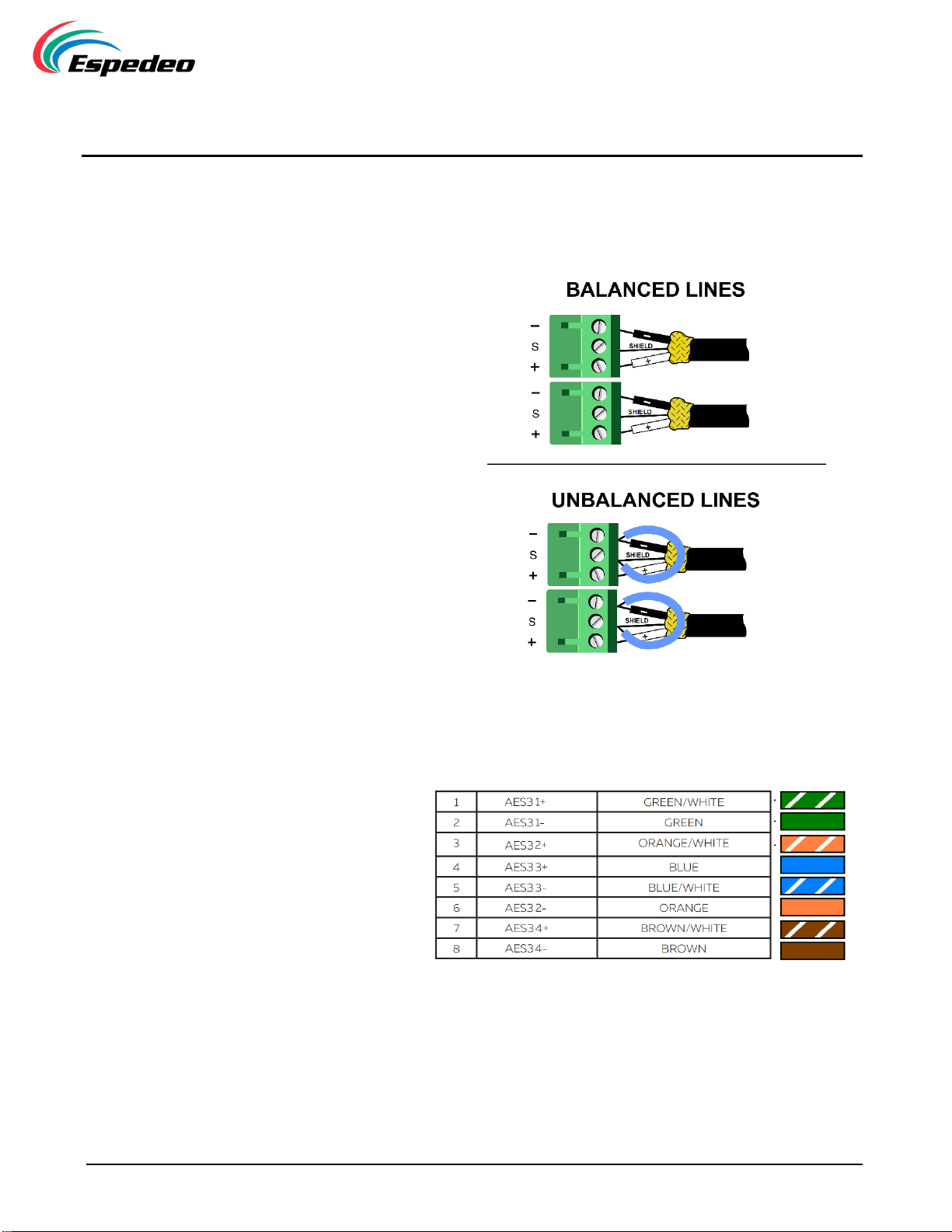
7. AES3 / Analog Output Connection
Analog Outputs
AES3 In
-11 -
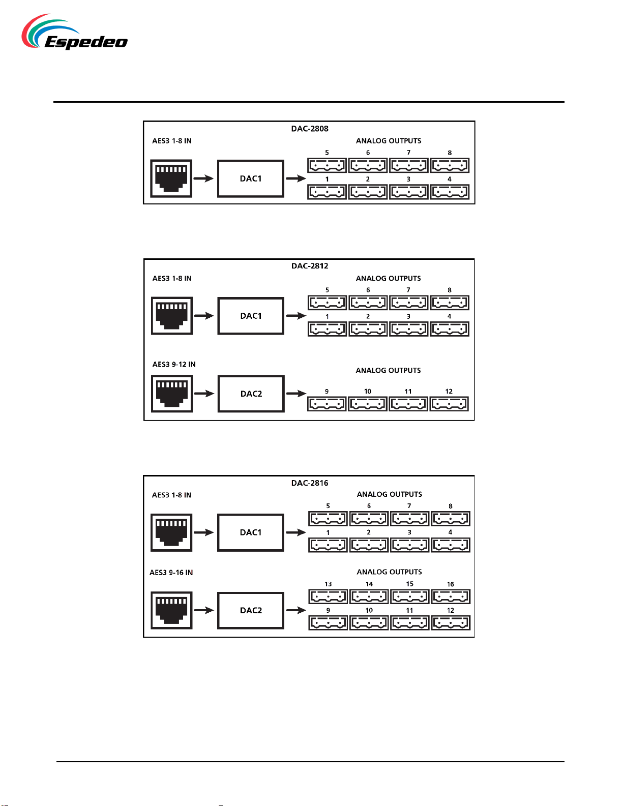
8. Routing Diagram
Figure 2: Routing Diagram for DAC-2808
Figure 3: Routing Diagram for DAC-2812
Figure 4: Routing Diagram for DAC-2816
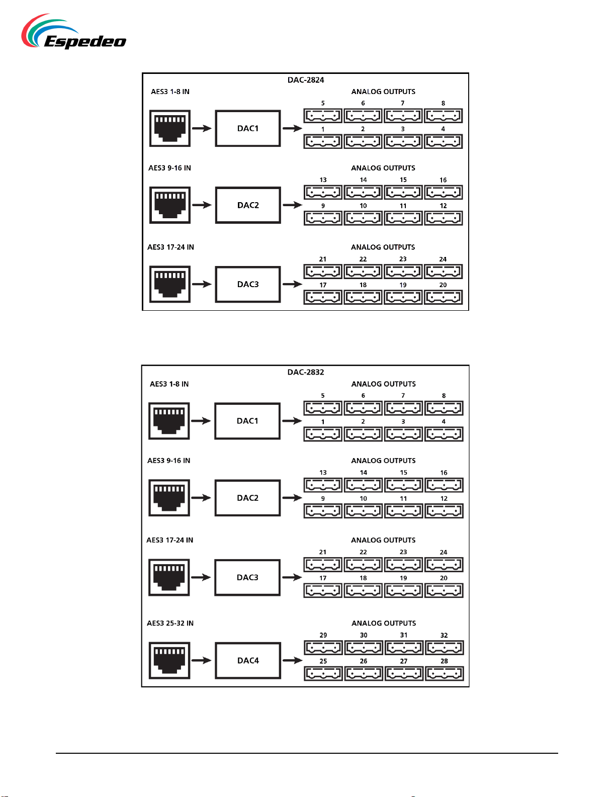
-12 -
Figure 5 : Routing Diagram for DAC-2824
Figure 6: Routing Diagram for DAC-2832
-13 -
9. Installation and Panel Description
9.1 Installation
The DAC-28xx Digital-to-Analog Audio Converter is a 1U Rack device and can most conveniently be
installed in the amplifier rack it connects to.
NOTE:Instead of connecting the DAC-28xx to the power grid directly, it is recommended to plug the device’s
mains connection to a UPS outlet.
9.2 AC Mains Supply
The AC Main connection is made via the IEC C13 connector.
The DC series amplifiers have an automatic power factor correction system - PFC - for a perfect mains
network interface. The PFC minimizes the reactive power reflected on the network and reduces the harmonic
distortion on voltage/current waveform: in this way the amplifier is seen as a resistive load from the mains
network. Furthermore, the system allows performance to be maintained even in case of varying mains voltage.
-14 -
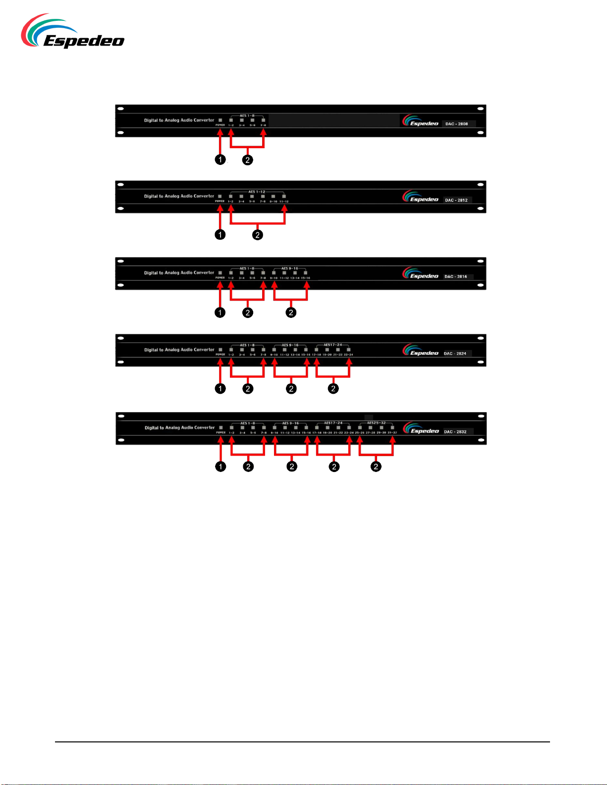
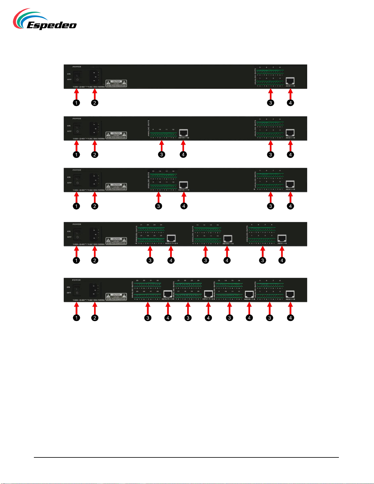
9.3 Front Panel of DAC Series
Figure 7: DAC Series Front Panel
①→Power indicator
②→AES3 Input Signal Indicators
-15 -
9.4 Rear Panel of DAC Series
Figure 8: DAC Series Rear Panel
①→Power Switch
②→Equipment Power Supply:
C14 mains socket. AC 100V - 240V 1.0A Max. 50/60Hz.
The following power cord types are supplied with DAC Series unit, depending on the
shipment region:
▪EU - Type F - C13
▪US - Type B - C13
▪UK - Type G - C13
▪CN - Type I - C13
▪IN - Type M - C13

-16 -
③→AES3 Input:
8-channel AES3 signal input. RJ-45 connector receives the AES3 stream which can be routed to analog
output as mentioned below:
DAC-2808/-2812/-2816/-2824/-2832 (wherever applicable):
▪AES3 1-8 IN - Analog Outputs 1-8
▪AES3 9-12 IN - Analog Outputs 9-12
▪AES3 9-16 IN - Analog Outputs 9-16
▪AES3 17-24 IN - Analog Outputs 17-24
▪AES3 25-32 IN - Analog Outputs 25-32
④→Phoenix Analog Outputs:
8 x 3 pin Phoenix connectors provide analog output for connection to analog amplifiers.
-17 -
Copyright © 2023 Espedeo Holdings Limited. All rights reserved.
All trademarks listed on this website are properties of their respective owners.
Specifications are subject to change without notice due to ongoing product development and improvement.
Espedeo Website
Contact Us
Technical Support
Worldwide Offices
This manual suits for next models
5
Table of contents


