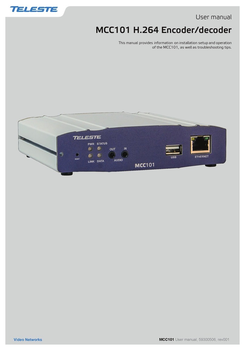
Teleste EASI IP Series User manual

EASI™IP Series
User Manual
BLUEbox MPEG-2 encoder & decoder
BLUEbox user manual, 59300233, rev002

BLUEbox series user manual rev002
Introduction..................................................................................................................................................................... 1
General .................................................................................................................................................................... 1
Software version...................................................................................................................................................... 1
Features................................................................................................................................................................... 1
Installation....................................................................................................................................................................... 2
Quick instructions .................................................................................................................................................... 2
Mechanical connections .......................................................................................................................................... 3
Indicator leds ........................................................................................................................................................... 3
Connections.................................................................................................................................................................... 4
General .................................................................................................................................................................... 4
Video connection ..................................................................................................................................................... 4
Audio connections ................................................................................................................................................... 4
Data connections..................................................................................................................................................... 5
Mgmt connection ..................................................................................................................................................... 6
Ethernet connection................................................................................................................................................. 7
Changing the settings of EASITM BLUEbox devices................................................................................................... 8
General .................................................................................................................................................................... 8
Web user interface (WebUI) .................................................................................................................................... 8
Command line interface (CLI) ................................................................................................................................. 8
User groups ............................................................................................................................................................. 8
Web user interface (WebUI)........................................................................................................................................... 9
Introducion ............................................................................................................................................................... 9
General .................................................................................................................................................................... 9
Operation ................................................................................................................................................................. 9
Starting ...................................................................................................................................................................10
User groups for WebUI ...........................................................................................................................................10
General information - page.....................................................................................................................................11
Network configuration - page..................................................................................................................................12
Video configuration - page......................................................................................................................................13
Video management - page .....................................................................................................................................14
SAP management - page........................................................................................................................................15
Video statistics - page ............................................................................................................................................16
Change password / User management - page.......................................................................................................17
Services - page.......................................................................................................................................................18
Data channel 1...3 - pages......................................................................................................................................19
Data channel statistics - page ............................................................................................................................... 20
Command Line Interface - CLI..................................................................................................................................... 21
Connection methods - Hyper Terminal.................................................................................................................. 21
Connection methods - Telnet................................................................................................................................. 22
How to use the CLI........................................................................................................................................................ 23
CLI levels ............................................................................................................................................................... 23
Detailed descriptions of commands .......................................................................................................................... 24
Disable level........................................................................................................................................................... 24
Enable level............................................................................................................................................................ 25
Config level ............................................................................................................................................................ 26
Config-if level for data channels ............................................................................................................................ 27
Config-if level for Fast Ethernet ............................................................................................................................. 28
Config-sap level ..................................................................................................................................................... 29
Config-ts level ........................................................................................................................................................ 30
Config-filter level .................................................................................................................................................... 31
Config-line level ..................................................................................................................................................... 32
Glossary....................................................................................................................................................................33-38
Copyright acknowledgements .................................................................................................................................... 39
Technical specifications .............................................................................................................................................. 40
Contents

Welcome, and thank you for purchasing Teleste’s
EASI™ Products.
General
EASI™ BLUEbox is a stand-alone video, audio & data
Encoder/Decoder device for business television
type applications.
The permitted supply voltage range is 10.5...18 V DC.
The power consumption is 6 W. The permitted operational
temperature range is -10...+55 °C.
These devices provides not only a transparent link of
PAL or NTSC video signal, but also two uni-directional
audio channels and three independent separately
configurable general-purpose asynchronous data
channels in both directions.
BLUEbox MPEG-2 Encoder (BBE) makes up pair with
BLUEbox MPEG-2 Decoder (BBD).
The transmission is accomplished over 10/100Base-Tx
network utilizing TCP/UDP/IP streaming.
These devices are equipped with an MPEG-2 video
compression engine compliant with the ISO/IEC 13818-2
standard. Audio is compressed in the same direction with
video, as described in ISO / IEC 11172-3 MPEG-1 audio
compression standard.
General-purpose asynchronous data channels are
transferred separately from encoded video and audio signals.
Software version
Device functional and operational suitability described in this
manual is for software version BBE 2.4.1 and BBD 2.4.23.
Features
• Selectable CVBS and Y/C video input and output
• Frame rate 25 (PAL), 30 (NTSC)
• Video bit rate scalable up to 3000...10000 kbps
• GOP structure selectable
• Balanced audio input and output
• Bi-directional data interface (EIA232/422/485), user
data rate up to 115kbps / Channel
• Web User Interface / Command Line Interface
• Low latency mode
Stand-alone CAT5 devices with one video, two audio
and three data channels, In-band management
D
x3
A
x2
E
x1
M
gmt
V
x
1
BLUEbox encoder & decoder introduction
BLUEbox series user manual rev002 1

Quick Instructions
Install the stand-alone BLUEbox device to the installation place.
A 12 V supply voltage is provided by a CPS22x mains adapter.
Switch on the system power and see that the “module”, “link”
and “video” -indicators on the front panel of the device are lit.
The “module” should lit green to show that hardware is
operating properly.
Connect all needed audio/data signals to their respective
connectors on the device’s rear panel.
Connect either a CVBS video signal to the BNC connector or a
S-VIDEO signal to the mini-DIN connector of the device.
Connect the Ethernet 100Base network to port “10/100Base-Tx”
in the rear panel.
Note! You can create a local WebUI connection by this
connector using an Ethernet cable (e.g. OPUS1CCC0050X
cross-connection cable).
Create management connection to the device either by over an
Ethernet network or by a Mgmt port and then set all necessary
settings in the device.
Default network addresses for the devices are are the following:
BBE: 10.9.96.10 (IP address)
BBD: 10.9.96.20 (IP address)
BBE/BBD: 255.255.255.0 (Netmask address)
Make sure that the device is not indicating any alarms or
warnings. The “module”, “link” and “video” -indicators on the
front panel should now lit green. If the “module” indicator is red,
the device in question has a module error and is giving an alarm.
Installation
1
2
3
4
5
6
7
2 BLUEbox series user manual rev002

BLUEbox Mechanical Connections
1. Composite (CVBS) video input / output (BBE / BBD),
BNC female connector.
2. S-video (Y/C) input / output (BBE / BBD), 4 pin
min-DIN female connector.
3. 2 audio inputs / outputs (BBE / BBD), RJ-45
female connector.
4. 3 EIA-RS data interfaces, RJ-45 female connector.
5. Management interface for device’s local
management operation, RJ-45 female connector.
6. Ethernet 10/100Base interface (CAT-5), RJ-45
female connector.
7. Supply voltage connector (+ 12 VDC)
Indicator Leds
There is three dual colour leds on the front panel;
video-led indicates state of video, link-led indicates
state of Ethernet connection and module-led indicates
state of hardware.
The “video”, “link” and “module” -indicators on the front
panel should lit green in normal operation. If the led
indicator is red or yellow, the function in question has a
error and is giving an alarm.
Picture 1.
BBE Mpeg-2
Encoder / connections.
Picture 2.
BBD Mpeg-2
Decoder / connections.
Video S-Video Audio L Audio R Data 1 Data 2 Data 3 Mgmt 10/100Base-T 12 VDC
1
2
3
4
5
6
7
Video S-Video Audio L Audio R Data 1 Data 2 Data 3 Mgmt 10/100Base-T 12 VDC
1
2
3
4
5
6
7
BLUEbox series user manual rev002 3

General
All products in EASI™ IP family have the same connection scheme in
their connectors. Depending on the model, there are Video, S-Video,
Audio, Data, Mgmt & Ethernet 100Base-TX connections.
Video,
audio, data and Ethernet port settings can be configured from web
user interface (WebUI) or command line interface (CLI).
Video Connection
The video connection provides one uni-directional video channel line
(BBE -- > BBD). The video connector is either type BNC female
(CVBS) or a 4 pin min-DIN female (S-video, see picture 3).
The impedance of the video (input/output is) 75 Ω. The nominal
input/output level is 1 Vpp.
When the Video connection status is OK, the “video” led on the front
panel is green. If the video signal is missing or it’s level is too low, the
“video” led is yellow.
Audio Connections
The audio connectors (1 & 2) provide one uni-directional audio
channel line (BBE -- > BBD). The audio impedance is constant and
cannot be adjusted. The audio input impedance is >10 kΩand the
output impedance is <10 Ω. The connector is type RJ-45 female
(see picture 4 and table 1 for detailed description).
Connections
43
12
Picture 3. S-video connector
(4 pin min-DIN female).
Pin 1 - Ground (Y)
Pin 2 - Ground (C)
Pin 3 - Luminance (Y)
Pin 4 - Chrominance (C)
Audio
Picture 4.Audio connector.
Table 1. Audio connector’s pinout.
Pin BBE BBD
Audio 1 Audio 2 Audio 1 Audio 2
1 Ground Ground Ground Ground
2 Mgmt out Mgmt out
3 Ground Ground Ground Ground
4 out + out +
5 out - out -
6 Mgmt in Mgmt in
7 in + in +
8 in - in -
4 BLUEbox series user manual rev002

Data Connections
The data connectors (1, 2 & 3) provide one bi-directional data
channel (BBE <--> BBD). The data type can be set to RS232,
RS422, RS485-2w or RS485-4w. You can configure data settings
by help of WebUI or CLI. The connector is type RJ-45 female
(see picture 5 and table 2 for detailed description).
Table 2. Data connector’s pinout and supported data types.
Pin RS232 RS422 RS485-2w RS485-4w
1 out + in / out + out +
2 out out - in / out - out -
3 in - in / out - in -
4
5 Ground Ground Ground Ground
6 in in + in / out + in +
7
8 Ground Ground Ground Ground
Data
Picture 5.Data connector.
BLUEbox series user manual rev002 5

Management Connection
The Mgmt (Management) connector provides one bi-directional data
channel (RS232). The Mgmt connection is meant for configuration
and controlling of BLUEbox devices locally by CLI. Management
connection between BLUEbox devices and e.g. laptop is based on a
serial data communication by means of any terminal type program
(e.g Windows Hyper Terminal). Management software for BLUEbox
devices is a Command Line Interface (see page 21 for detailed
description). The Mgmt connector is type RJ-45 female (see picture
6 and table 3 for detailed description). The management cable is
type CIC504 (see table 7 on page 8 for pinouts).
Picture 6. Management connector.
Table 3. Mgmt connector’s pinout.
Pin Signal
1
2 Mgmt out
3
4
5 Ground
6 Mgmt in
7
8 Ground
6 BLUEbox series user manual rev002

Led Colour Speed Mode
2 Green 100 Mbps Full Duplex
Blinking Green 100 Mbps Half Duplex
Orange 10 Mbps Full Duplex
Blinking orange 10 Mbps Half Duplex
Ethernet Connection
The Ethernet connector provides 10/100Base-TX Ethernet network
interface. The connector is type RJ-45 female (CAT5, see picture 7
and table 4 for detailed description).
When the Ethernet connection status is OK, the “link” led on the
front panel is green. If the Ethernet signal is missing or it’s level is too
low, the “link” led is yellow.
Note! It is also possible to create Web User Interface (WebUI)
connection locally into the device via this Ethernet connector.
Table 6. Ethernet connector’s led 2 / indicator lights.
Picture 7. Ethernet connector (CAT5).
Table 4. Ethernet connector’s pinout (CAT5).
Pin Signal
1 Tx +
2 Tx -
3 Rx +
4
5
6 Rx -
7
8
Led Colour Ethernet signal
1 Yellow On stream
Blinking yellow Interface up
Dark Signal is missing or it’s level is too low
Table 5. Ethernet connector (RJ-45) / led 1 indicator lights.
BLUEbox series user manual rev002 7

How to change the settings
General
This chapter tells how you can configure and check the settings of
BLUEbox device with help of web user interface (WebUI) or
command line interface (CLI).
Web User Interface (WebUI)
Teleste’s WebUI provides an user friendly way to configure and
manage BLUEbox device. WebUI session can be accessed using
Internet browser such as Internet Explorer. See next page for
detailed description.
Command line interface (CLI)
Teleste’s BLUEbox device includes also a text-based user interface
(CLI) for configuration purposes.
System Requirements:
* PC equipped terminal emulation program e.g. Hyper Terminal
(supporting VT100 / 102 or ANSI protocols).
* RS232-cable (type Teleste CIC504), see table 7 for cable pinout
* Cross-connected Ethernet cable (e.g. Teleste OPUS1CCC0050X
when using TCP/IP connection).
CLI is accessed Locally via Mgmt connector with a serial connection
cable (CIC504) and any terminal emulation type program (e.g. Hyper
Terminal) or Remotely via TCP/IP connection (e.g. Telnet).
The command structure is the same for both session types.
See page 21 for detailed description.
PC/PSION D9 female RJ-45 male BLUEbox
Receive data 2 2 MGMT output
Transmit data 3 6 MGMT input
System ground 5 1 Ground
Table 7. RS232 cable (CIC504) pinout (D9 female / RJ-45 male).
User groups
There are four different groups of authority, which are determined by
the username and password (see table 8). The username and
password can be change: CLI config level (page 26) and
WebUI (page 17).
guest guest guest
technician tech tech
operator oper oper
administrator admin admin
User Group Default Default Authority
Username Password
Read only access to general pages
Read only access to all pages
Read and write access to all pages
and operational settings
Read and write access to all pages
and all settings
Table 8. User groups
8 BLUEbox series user manual rev002

Web User Interface (WebUI)
Introduction
This chapter tells how to configure the settings using web
user interface.
General
The BLUEbox Encoders (BBE) and the BLUEbox Decoders
(BBD) are fully controllable with the Web User Interface (WebUI).
System Requirements:
* The PC equipped with an Ethernet Network card and an
Internet browser installed.
* Cross-connected Ethernet cable
(e.g. type OPUS1CCC0050X).
You can access the Web User Interface locally via Ethernet
connector or remotely over an TCP/IP Ethernet connection.
Operation
Web User Interface window consists of several pages. Only one
page is completely visible at one time. You can activate a page
simply by clicking the page’s heading (see picture 10).
The Web User Interface has the following configuration display
pages that are introduced in this document:
- General Information
- Network Config
- Configuration
- Video Management
- SAP Management
- Statistics (video statistics, only in BLUEbox Decoder)
- Change Password
- User Management
- Services
- Data Channel 1
- Data Channel 2
- Data Channel 3
- Statistics (data channel statistics)
The information on configuration sheets is shown in data fields
or boxes. You can change settings in data fields or boxes whose
background is white. Place your cursor in the desired data field or
box and enter the new setting. Some settings are entered by
ticking a checkbox or clicking on a radio button, by selecting from
a pull-down list or by scrolling digits with the help of spin buttons.
Information without datafield or box is read only parameter and
can not be change.
BLUEbox series WebUI user manual rev002 9

Picture 8. Web User Interface’s start page.
Picture 9. Authorization window.
Starting
To create the WebUI session to the
device, first enter device’s IP address into
the web browser’s address.
Encoder’s default factory IP address is
10.9.96.10 and Decoder’s default factory
IP address is 10.9.96.20.
The following Web User Interface’s start
page will appear on the screen
(picture 8).
Click login to continue --> “Enter Network
Password” window appears on the screen
(picture 9).
Write the required username and
password in the fields and then
click OK button to continue --> Web
User Interface’s “General Information”
page appears on the screen
(picture 10 & 11).
The Web User Interface session to
BLUEbox device is now completed.
User Groups for WebUI
There are four different groups of
authority, which are determined by the
username and password
(see table 8 on page 8 for User groups).
The username and password can be
change on Administration page
(page 17).
10 BLUEbox series WebUI user manual rev002

General
Note! Always click Apply button to activate settings.
Note! Click Refresh button to update the page view.
BLUEbox series WebUI user manual rev002 11
General information
Click heading “General Information”
under the General menu on the left
column. General information / device
information window appears on the right
side of page (picture 10 & 11). On this
page you can see device’s general
settings and change device’s hostname.
Hostname:
User definable alias name for
the device (uniquely identifies each device
of a network). Click ppl button to
confirm a hostname for the device
SW Version: Device software version
Hardware: Device hardware type
HW Version: Device hardware version
Bootloader Version: Device
bootloader version
Serial Number: Device serial number
Picture 10. General information page (BBE).
Picture 11. General information page (BBD).

12 BLUEbox series WebUI user manual rev002
Network configuration
Click heading “Network Config” under
the General menu on the left column.
Network configuration / ethernet
information window appears on the
right side of page (picture 12 & 13).
On this page you can see and change
device’s Ethernet network settings.
DHCP: DHCP server operation enabled/
disabled. If enabled, the device gets its IP
address from the DHCP server.
IP Address: IP address of device.
Note! If this is changed, a new contact
with the new IP address must be
assigned to be able to continue with
WebUI session.
Netmask: Mask for subnet definition.
Gateway: Gateway address for router
definition. Gateway address is necessary
for multicasting video. Device and
gateway addresses should be in the
same network.
Note! Gateway address should be set
before enabling multicast video.
Ethernet MAC: Device MAC address.
Speed: Network connection speed.
Duplex: Network connection type
(half / full).
Link Status: Network connection status.
OK indicates that network connection
works and error indicates that network
connection does not work.
IP Routes:Network parameters
(see glossary for detailed descriptions).
network:
netmask:
gw:
interface:
Picture 12. Network config page (BBE).
Picture 13. Network config page (BBD).

Video
Video configuration
Click heading “Configuration” under the
Video menu on the left column.Video
configuration / video stream window
appears on the right side of page
(pictures 14 & 15).
On this page you can modify device’s
video interface configuration.
Video Enable:
BBE: Sets video encoding enable / disable
BBD: Sets video decoding enable / disable
Streaming Status:
Video indicator (BBE).
(OK/stopped/invalid configuration/error)
Camera Status: Video indicator (BBE).
(OK/not detected)
Video State: Video indicator (BBD).
(active/waiting/inactive/error)
IP Address:
BBE: In multicast case, see note*. In
unicast video case, the IP address should
be receiving decoder device’s
BBD:
In multicast case, see note*. In
unicast video case, the field should be blank
UDP Port: UDP port number. This number
has to be same at both encoder and
decoder pairs
Multicast TTL: “Time to live” value, can
be set 1 to 255 (BBE)
Video Input: Video input type, either
composite (CVBS) or S-video (BBE)
Video Format: Video format type, either
PAL or NTSC
Video PID: MPEG-2 video PID value.
This number has to be same at both
encoder and decoder pairs
Audio PID: MPEG-1 Audio PID value.
This number has to be same at both
encoder and decoder pairs
PCR PID: MPEG-2 PCR PID value
PMT PID: MPEG-2 PMT PID value (BBE)
Low Latency Mode: Video latency
setting. When enabled it reduces the
switching time between different video
sources (i.e.: camera touring). When
disabled it improves video-audio
synchronization. (BBD)
Stream Bitrate: Encoded video bitrate,
selectable 3, 4, 5, 6, 7, 8, 9 & 10 Mbps (BBE)
GOP Format: MPEG-2 GOP format,
selectable I, IP, IBP, IBBP (BBE)
Picture 14. Video configuration page (BBE).
Picture 15. Video configuration page (BBD).
Test Picture: Internally generated test picture
enabled / disabled (BBD).
Test Picture On Error Delay (s): Test picture
activating time in seconds when decoded video
is corrupted or missing.
* In multicast case there should be same IP address /
multicast group for video in Encoder and Decoder device.
Gateway address is necessary for multicasting video
(see Network configuration / Gateway, page 12).
Note! The gateway address should be set before enabling
the multicast video.
BLUEbox series WebUI user manual rev002 13

Video management
Click heading “Video Management”
under the Video menu on the left column
of page.
Video management / quality of
service (when BBE) / unicast video filtering
(when BBD) window appears on the right
side of page (pictures 16 & 17). On this
page you can modify device’s video Qos
and unicast video settings:
BBE:
QoS Precedence: Quality of service
level selection (class 0...4, best
effort=class 0)
Polling Service:
Polling service enabled/
disabled. This is needed to be enabled at
all BBE encoders which are transmitting
the unicast video to the same BBD
decoder. Respectively, the unicast filtering
must be enabled on BBD decoder
BBD:
Filtering Service: Filtering service
enabled/disabled. When enabled, the
BBD decoder will be locked to the first
received unicast video stream.
Respectively, the unicast filtering must be
enabled on BBE encoder
Accepted Video Source IP Address:
Defined source IP address. If left empty,
the BBD decoder will be locked to the first
received video stream
Accepting video from: Actual source
IP address
Received stream from: List of available
sources IP addresses
Picture 17. Video management page (BBD).
Picture 16. Video management page (BBE).
14 BLUEbox series WebUI user manual rev002

SAP management
Click heading “SAP Management” under
the Video menu on the left column of page.
Sap management / session announcement
protocol window appears on the right side
of page (picture 18 & 19). On this page you
can modify device’s session
announcement protocol settings:
SAP Service: Service enabled / disabled
Multicast Group: SAP advertisements
global scope address as described in
RFC 2974. Default IP = 224.2.127.254
Port: SAP advertisements IP port number
as described in RFC 2974.
Default port = 9875.
Multicast Time-To-Live: SAP
advertisements number of hops between
routers. Should be 255 as described in
RFC 2974 (only in BBE)
Announcement Interval (s): SAP timing
in seconds. Retransmit time of SAP-
packet. This time has to be same at both
encoder and decoder pairs
Session Name: The name of the stream
associated with SAP-packet. This name
shows at the decoders SAP page
(only in BBE)
Session Info: Owner of the stream.
User can use own ID to detect ownership
of the stream. SAP application fills the
rest of the string (with user Id IPE12345
eg. IPE12345 IN IP4 xxx.xxx.xxx.xxx)
(only in BBE)
Received announcements: Display
received SAP announcements
(only in BBD)
Picture 18. SAP management page (BBE).
Picture 19. SAP management page (BBD).
BLUEbox series WebUI user manual rev002 15

Video statistics (only in BBD)
Click heading “Statistics” under the
Video menu on the left column.
Video statistics / transport stream window
appears on the right side of page
(picture 20). On this page you can see
BBD device’s video stream settings.
Video state: Display received video state
(active/waiting/inactive/error)
Detected bitrate: Display received
video bitrate.
Detected video Pid: Display received
video pid value.
Detected audio pid: Display received
audio pid value.
Detected pcr pid: Display received pcr
pid value.
Rx frames: Display total number of
received frames.
Picture 20. Video statistics page (only in BBD).
16 BLUEbox series WebUI user manual rev002

Administration
Change password
To change the password, first click
heading “Change Password” under the
Administration menu on the left column.
Administration / change password
window appears on the right side of page
(picture 21). On this page you can change
your username and password.
Note! Use only characters and numbers.
Do not use special characters!
Username: Username of which you are
logged in to the interface.
Old Password: Current password.
New Password: New password.
Retype New Password: Verification of
the new password.
User management
To access user management functions,
admin level access rights are needed.
To change the user information, first click
heading “User Management” under the
Administration menu on the left column.
Administration / user management
window appears on the right side of page
(picture 22).
On this page you can add/remove users
and change their passwords.
To add a new user,
first type the desired user name next to
button (picture 22).
Select the desired user group from pull-
down list on right side.
Click button to activate the
new user.
The new user will appear on the user list.
Note! Always click Apply button to
activate settings.
Picture 21. Change password page (BBE).
Picture 22. User management page (BBE).
BLUEbox series WebUI user manual rev002 17

To change the user password
First select user from users list by ticking
the checkbox before the username.
Write new password to the box after
button.
Click button to activate
the new password.
Note! Use only characters and numbers.
Do not use special characters!
To remove the user,
first select the user from users list by
ticking the checkbox before username.
Click button to remove user.
Note! Always click Apply button to
activate settings.
Services
To reboot or restart the device, first
click heading “Services” under the
Administration menu on the left column.
Administration / services window appears
on the right side of page (picture 24).
Click button to reboot the
device (this takes 90 seconds).
Click button to restart the device.
Picture 24. Services page (BBE).
Picture 23. User management page (BBD).
18 BLUEbox series WebUI user manual rev002
Other manuals for EASI IP Series
1
Table of contents
Other Teleste Media Converter manuals
