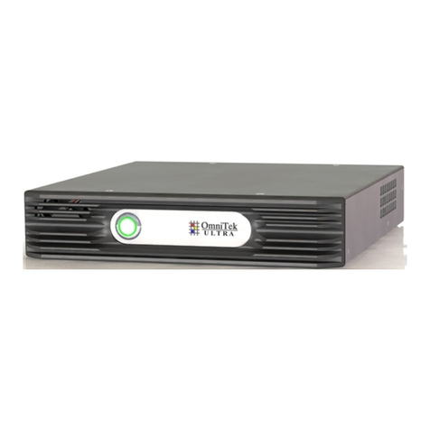
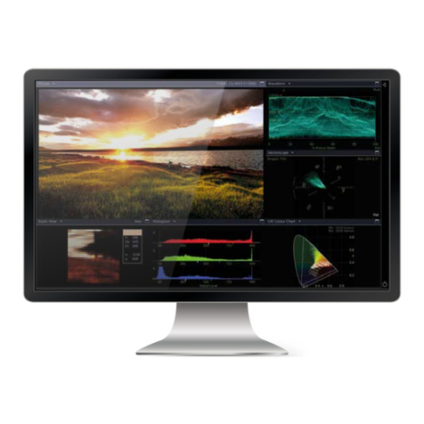
OmniTek Ultra 4K Tool Box User manual

Ultra
4K Tool Box
User Guide
Version: 2.0a
August 2015

Ultra v2.0a User Guide
© 2014-2015 Omnitek. All rights reserved
This documentation contains proprietary information of Omnitek. No part of this documentation
may be reproduced, stored in a retrieval system or transmitted in any form or by any means,
electronic, mechanical, recorded or otherwise without the prior written permission of Omnitek.
The information contained in this documentation was prepared by Omnitek with all reasonable
care and is believed to be accurate. However Omnitek does not assume responsibility for loss or
damage resulting from omissions, inaccuracies or errors contained herein. The information
contained in this document is subject to change and revisions hereto or new additions may be
issued to incorporate such changes.
Warranty
Omnitek systems are warranted for one year from date of purchase. This includes all feature
upgrades and bug fixes to the application software, plus repair or replacement of the hardware
(at the discretion of Omnitek). Extended warranty agreements are also available, please consult
your local dealer.
Contact Information
Omnitek
Intec Unit 3 Level 1, Wade Road, Basingstoke, Hants RG24 8NE, UK
Tel: +44 (0)1256 345900 Fax: +44 (0)1256 345901
Conventions Used in this Guide
The following typographical conventions are used:
Convention Meaning or Use
<item> Placeholder for item of the named type
Italic font Reference to a signal
Or: reference to a separate document
Bold font Reference to a file/software package
xxxxxx Link to additional information.

Ultra v2.0a User Guide
Contents
Section 1: General
A: Equipment Guide ................................................................................................................. A-1
A.1 Introduction ............................................................................................................. A-1
A.1.1 Safety Statement .............................................................................................. A-1
A.1.2 System Features ............................................................................................... A-2
A.1.3 Front and Rear Panels ...................................................................................... A-4
A.1.4 Instrument Options .......................................................................................... A-5
A.2 Installation ............................................................................................................... A-7
A.2.1 Preliminary steps: ............................................................................................ A-7
A.2.2 Typical Set-Up ................................................................................................ A-7
A.2.3 Set-Up Options ................................................................................................ A-8
A.3 Power Up ............................................................................................................... A-10
A.3.1 Power Requirements ...................................................................................... A-10
A.3.2 Start-Up Procedure ........................................................................................ A-10
A.3.3 Shutting Down ............................................................................................... A-11
A.4 The User Interface.................................................................................................. A-12
A.4.1 Button Bars .................................................................................................... A-12
A.4.2 ‘Properties’ .................................................................................................... A-13
A.4.3 User Interface Controls .................................................................................. A-13
A.4.4 Keyboard Alternatives ................................................................................... A-15
A.4.5 Presets Toolbar .............................................................................................. A-16
A.4.6 Saving Settings etc. to Disk ........................................................................... A-16
A.5 System Information ................................................................................................ A-17
A.5.1 System Details ............................................................................................... A-17
A.5.2 System Facilities ............................................................................................ A-19
A.5.3 Updating to the Latest Version ....................................................................... A-20
A.5.4 Installing Additional Facilities ....................................................................... A-20
B: System Configuration & Control ........................................................................................ B-1
B.1 Inputs, Outputs & Internal Connections: the Connections window ........................... B-1
B.1.1 Making Connections ........................................................................................ B-3
B.1.2 Selecting SDI Inputs ........................................................................................ B-4
B.1.3 Selecting SDI Outputs ..................................................................................... B-5
B.1.4 Using the DisplayPort Output .......................................................................... B-5
B.1.5 Setting the Output Video Standard ................................................................... B-5
B.1.6 Genlock ........................................................................................................... B-6
B.1.7 Interpolation Filter ........................................................................................... B-7
B.1.8 Connections needed to display Picture Images on a Monitor ............................ B-8
B.2 System Configuration .............................................................................................. B-9
B.2.1 Video Parameters ........................................................................................... B-10
B.2.2 System Parameters ......................................................................................... B-12
B.2.3 Licensed Facilities ......................................................................................... B-13
B.3 Presets ................................................................................................................... B-13
B.3.1 Recording Presets .......................................................................................... B-14
B.3.2 Preset Selection ............................................................................................. B-14
B.3.3 Changing the Name of a Preset ...................................................................... B-14
B.3.4 Deleting a Preset ............................................................................................ B-15
B.4 Import/Export of Settings etc. ................................................................................ B-15
B.4.1 Overview ....................................................................................................... B-15
B.4.2 Exporting Presets ........................................................................................... B-15
B.4.3 Importing Presets ........................................................................................... B-16

------------------------------------------- Contents -------------------------------------------
Ultra v2.0a User Guide
C: Automated Control .............................................................................................................. C-1
C.1 Background .................................................................................................................. C-1
C.2 Set-up ........................................................................................................................... C-2
C.3 Scope ............................................................................................................................ C-3
C.4 Automating a Test Procedure ....................................................................................... C-5
Section 2: Conversion Facilities
D: Format Conversion .............................................................................................................. D-1
D.1 Overview ...................................................................................................................... D-1
D.2 Setting up the Ultra to carry out the Required Conversion .......................................... D-2
G: Additional SDI Output Features ........................................................................................ G-1
G.1 Interlink Delay Insertion .............................................................................................. G-2
G.2 Jitter Insertion ............................................................................................................... G-3
G.3 Output Voltage and Slew Rate Control (SDI 4 only) ................................................... G-4
Section 3: Signal Analysis
H: The Viewer Window ............................................................................................................ H-1
H.1 Overview ...................................................................................................................... H-1
H.1.1 Screen Layout ...................................................................................................... H-2
H.2 Viewer Window Operations ......................................................................................... H-3
H.2.1 View Selection ..................................................................................................... H-3
H.2.2 Switching between Full Screen and Multiple Tile displays ................................ H-3
H.2.3 Configuring a View ............................................................................................. H-5
H.3 Focus of Analysis ......................................................................................................... H-5
H.4 Saving and Recalling Specific Tile Selections ............................................................. H-6
I: Pixel Data ................................................................................................................................ I-1
I.1 The Focus of the Display and its Movement Pixel-by-Pixel ........................................ I-2
I.2 Data View ...................................................................................................................... I-4
I.2.1 Configuration ........................................................................................................ I-6
I.3 Cable View .................................................................................................................... I-6
I.4 Ancillary Data Viewer .................................................................................................. I-7
J: Picture View ........................................................................................................................... J-1
J.1 Overview ....................................................................................................................... J-1
J.2 Displaying Picture Images ............................................................................................ J-2
J.2.1 System Setup ........................................................................................................ J-2
J.2.2 Picture View Selection ......................................................................................... J-3
J.2.3 Display Options .................................................................................................... J-3
J.3 Cursor ............................................................................................................................ J-3
J.4 Safe Action / Safe Title Cages ...................................................................................... J-4
J.4.1 Set-Up ................................................................................................................... J-5
J.4.2 Displaying the cages ............................................................................................. J-7
J.5 Zoom View .................................................................................................................... J-8
K: Image/Sequence Capture .................................................................................................... K-1
K.1 Overview ...................................................................................................................... K-1
K.2 Capturing images/sequences from the current input .................................................... K-2
K.3 Using Captured Images as Test Patterns ...................................................................... K-3
K.4 Allocating Memory to Capture .................................................................................... K-4

------------------------------------------- Contents -------------------------------------------
Ultra v2.0a User Guide
L: Waveform Display ................................................................................................................ L-1
N: Gamut Analysis .................................................................................................................... N-1
N.1 Gamut Meters ............................................................................................................... N-1
N.1.1 Setting the Permitted Ranges ............................................................................... N-2
N.1.2 Selecting the Colour Components to be Displayed ............................................. N-2
O: Status ..................................................................................................................................... O-1
O.1 The Status View ........................................................................................................... O-1
O.1.1 Selection .............................................................................................................. O-2
O.1.2 Error Ranges, Persistence and Severity ............................................................... O-2
O.1.3 Resetting Error Counts ........................................................................................ O-2
O.2 Video Information Displayed ....................................................................................... O-2
Section 4: Physical Layer Analysis
S: Eye & Jitter Measurement ....................................................................................................S-1
S.1 Overview .......................................................................................................................S-1
S.1.1 Facilities Offered ..................................................................................................S-3
S.1.2 Set-Up ...................................................................................................................S-3
S.2 Eye Waveform ...............................................................................................................S-4
S.2.1 Selecting the Eye Waveform display ....................................................................S-5
S.2.2 Configuring the Eye Waveform display ...............................................................S-5
S.2.3 Obtaining Signal Parameters from the Eye Waveform ........................................S-6
S.2.4 Transmission Integrity ..........................................................................................S-6
S.3 Jitter ...............................................................................................................................S-7
S.3.1 Selecting Jitter displays ........................................................................................S-7
S.3.2 Jitter Meters ..........................................................................................................S-7
S.3.3 Jitter Spectrum ......................................................................................................S-9
S.3.4 Jitter Histogram ..................................................................................................S-11
S.3.5 Jitter Waveform ..................................................................................................S-12
S.3.5 Jitter Insertion .....................................................................................................S-13
T: Timing Measurement ........................................................................................................... T-1
T.1 Overview ...................................................................................................................... T-1
T.2 Set-Up ........................................................................................................................... T-2
T.2.1 Set-Up for Measurement against an External Reference Signal ......................... T-2
T.2.2 Set-Up to give Line-Based Timings .................................................................... T-3
T.3 Comparing the Timing of Constituent Inputs .............................................................. T-3
T.4 Comparing Timing against an External Reference ...................................................... T-4

------------------------------------------- Contents -------------------------------------------
Ultra v2.0a User Guide
Section 5: Generator
V: Generator Basics .................................................................................................................. V-1
V.1 The Generator Window ................................................................................................ V-1
V.1.1 Selecting the Generator Window ......................................................................... V-2
V.1.2 Controls ............................................................................................................... V-2
V.2 Test Patterns from Still Images .................................................................................... V-3
V.2.1 Importing Still Images ......................................................................................... V-3
V.2.2 Playing Out Test Patterns .................................................................................... V-4
V.2.3 Image Data ........................................................................................................... V-4
V.3 Test Sequences ............................................................................................................. V-5
V.3.1 Creating Standard Test Sequences ...................................................................... V-5
V.3.2 Importing Sequences stored on disk .................................................................... V-5
V.3.3 Playing out a Sequence ........................................................................................ V-6
V.4 Cloning Test Patterns ................................................................................................... V-7
V.5 Deleting Test Patterns .................................................................................................. V-7
V.6 Playing-Out a Series of Test Patterns ........................................................................... V-8
W: Creating Test Patterns ....................................................................................................... W-1
W.1 Line (Colour Bar) Patterns .......................................................................................... W-1
W.1.1 Adding a New Line Pattern ................................................................................ W-1
W.1.2 Configuring the Line Pattern .............................................................................. W-2
W.1.3 Modifying an existing Line Pattern .................................................................... W-3
W.2 Zone Plates .................................................................................................................. W-3
W.2.1 Adding a New Zone Plate ................................................................................... W-3
W.2.2 Modifying an existing Zone Plate ...................................................................... W-5
W.3 Combination Test Patterns .......................................................................................... W-5
W.4 Saving Patterns on Disk .............................................................................................. W-6
W.4.1 Saving Patterns ................................................................................................... W-6
W.4.2 Importing Saved Test Patterns/Test Pattern Sets ................................................ W-7
X: Modifying the Output .......................................................................................................... X-1
X.1 Overview ...................................................................................................................... X-1
X.2 Resizing Images ........................................................................................................... X-2
X.3 Luma/Chroma Adjustments ......................................................................................... X-2
X.3.1 Selecting the Colour Range ................................................................................. X-3
X.3.2 Adjusting the Gamma .......................................................................................... X-3
X.4 Image Panning .............................................................................................................. X-3
X.4.1 Setting an Image to Pan ....................................................................................... X-4

Ultra v2.0a User Guide
Section 1: General
This section introduces the facilities offered by an Omnitek Ultra system, explains
how to set it up and describes how it is controlled.
It also gives general maintenance advice and describes the steps used to upgrade to
the latest version of the Ultra software and to add software options.
Note: Throughout this guide, steps are described in terms of mouse operations such
as clicking. Where the user interface to Ultra is displayed on a touch-screen device,
substitute the equivalent finger actions.

------------------------------------------- General -------------------------------------------
Ultra v2.0a User Guide

Ultra v2.0a User Guide A-1
A : Equipment Guide
A.1 Introduction
The Omnitek Ultra 4K Tool Box combines in a single box a video format converter capable of
up/down/cross conversion, colour and image manipulation in all current and anticipated 4K video
formats up to 4096 x 2160/60, with waveform analysis and video generation across the same
range of video formats. In doing so, it offers a complete solution to the conversion and analysis of
Ultra HDTV and Digital Cinema signals, allowing manufacturers, designers, researchers,
broadcast stations, networks, outside broadcast units and systems integrators to build, test and
commission 4K products and systems with complete confidence.
The Omnitek Ultra is also available as a standalone 4K Analyser or 4K Converter or 4K Test
Signal Generator or as any combination of those roles.
All four versions of the Ultra offer of a variety of connection formats – multi-rate SDI, HDMI and
DisplayPort – for both video source and display. Conversion between physical and image formats
allows operation in multi-format video environments, while comprehensive SDI eye and jitter
analysis features (available as an optional extra) enable system designers to rapidly locate sources
of signal error in all signal paths up to 12G-SDI single link 4K.
A.1.1 Safety Statement
To avoid injury and prevent damage to the Ultra or to any products connected to it, use this product
only as specified and take the following safety precautions. Where the Ultra is being used
alongside other equipment, you must also ensure that you act in accordance with the advice given
in the documentation supplied with those other products.
Only use the power cord that is both specified for this product and certified for the country
of use.
Ensure that the product is properly grounded through the grounding conductor within the
power cord.
Ensure that it is always possible for the user to switch off the power to the unit if need be.
Keep all product surfaces clean and dry.
Ensure that the unit is properly ventilated.
Do not operate in an explosive atmosphere or in damp/wet conditions.
Do not operate the Ultra with either the cover or any of the panels removed or otherwise
displaced from their standard positions.
Do not operate an Ultra that has been damaged (or that you suspect has been damaged).
When replacing the power supply fuse, only use a fuse of the specified type and rating.
When replacing the on-board battery, only use a battery of the specified type and rating.
Do not connect or disconnect test leads while they are connected to a voltage source.
Do not touch exposed connections and components without first disconnecting the unit
from mains power.
Please note: The only user-serviceable parts are the fuse associated with the power supply and the
battery on the motherboard that backs up the system clock. There are no other user-serviceable
parts. In particular, the SD card on which the Ultra software is supplied is not a user-serviceable
device: swapping this card out will remove calibration data.

-------------------------------- General: Equipment Guide ---------------------------------
Ultra v2.0a User Guide
A-2
A.1.2 System Features
The main features of the Ultra system are summarised in the following table.
Users upgrading to Ultra V2 from V1 should note that replacement hardware will be needed to
support the new 12G features. It will also be needed to take advantage of the facility to adjust
signal amplitude and slew rate.
Feature
Description
Control System
Web-based UI displayed on handheld device or networked PC
or ‘Local’ UI displayed on monitor attached to Ultra and
driven from mouse/keyboard plugged into Ultra
or Remote control via SNMP.
UI comprises set of windows, dedicated to Connection, Configuration,
Video Analysis ‘Viewer’ and Test Signal Generation. Range of ‘Soft’
buttons offering context-sensitive selection of actions.
Video Formats
Supported
All current and anticipated video formats up to 4096 x 2160/60,
delivered via SD/HD/3G/6G SDI, HDMI 1.4 or DisplayPort 1.2 are
supported as standard (Note: HDMI input only available for
conversion to other standards. DisplayPort output only in the current
version). Support for 12G SDI is available as an optional extra.
Note: A full list of the video standards supported by Ultra systems can
be downloaded from the Manuals etc. page of the Omnitek website.
Configuration
Input and Output formats and routing are configured via a
‘Connections’ window. System parameters are configured via
‘Configuration’ window. Analysis displays (where offered) are
configured via on-screen options and drop-down menus.
Presets
Save and re-call of up to 9 sets of System Configuration, Video
Configuration and Connection settings. Similar ability to save and
recall up to 9 ‘Viewer’ window layouts complete with details of the
individual Views displayed and Generator pattern selections (where
supported).
Format Conversion (4K Tool Box and 4K Converter):
Up/Down/cross
conversion
Offered across entire range of supported video formats.
Analysis (4K Tool Box and 4K Analyser: SDI video only):
Monitoring system
Centred around a single ‘Viewer’ window – divided into four ‘tiles’,
each of which may be used to show the result of a separate type of
analysis applied to the video under test. Individual tiles may be shown
full screen and scrolled to similarly show the next/previous tile.
General Features
Analysis of full raster/active picture area. Fully digital processing.

-------------------------------- General: Equipment Guide ---------------------------------
Ultra v2.0a User Guide
A-3
Feature
Description
Picture Display
Full-resolution video images can be displayed as part of the Viewer
window where the User Interface is displayed on an HDMI monitor.
The Aspect ratio is taken from AFD data.
Safe Area and Safe Title cages can also be shown.
Status Information
Comprehensive Status information with automatic flagging of errors.
Pixel Data
Display of data from both the active area and from the blanking, shown
both in terms of the different ‘virtual interfaces’ (or ‘Inputs’) contributing
to an image and in terms of the data delivered on each cable. ANCs
interpreted and displayed on an associated screen. Current cursor position
in image linked across multiple data streams.
Gamut
Monitored as part of Status information. Also presented in form of bar
charts for each colour component.
Timing
Ability to make both Reference Timing and Relative Timing
measurements.
Physical Layer Analysis (4K Tool Box and 4K Analyser with PHY option):
Physical Layer
Analysis
Option of Eye and Jitter displays and measurement of SDI signal
characteristics across all video standards up to 6G. Addition of
PHY_ADV option extends the range of signal standards supported to
include 12G and adds Jitter Spectrum, Jitter Histogram and Jitter
Insertion (for test purposes) to the facilities offered.
Test Signal Generator (4K Tool Box and 4K Generator):
Test Pattern
Generation
Test signals generated in all video formats from patterns derived from
still images, line patterns and zone plates. Images taken from stored files;
line patterns and zone plates generated within the Ultra from presets.
Easy export and import of both source files and derived patterns.
Option of fixed
Background +
Moving
Foreground
Test Patterns can comprise an image or a line pattern overlaid with a
zone plate. Another option is to divide the Test Pattern into segments
that pan at different speeds as the Test Pattern is played out.
Additional Features for SDI Video:
Interlink Delay
Insertion
Provided with the Generator: Ability to adjust the timing of the
individual signals within a multi-link video format by up to 128 pixels
(depending on the video format).
SDI Jitter insertion
Provided with the PHY_ADV option: Option of inserting jitter into SDI
video, e.g. for testing the robustness of an SDI connection.
Output Voltage
Control
Provided with the PHY_ADV option: Ability to mimic the effect of a long
cable by reducing the signal amplitude and adjusting the slew rate.

-------------------------------- General: Equipment Guide ---------------------------------
Ultra v2.0a User Guide
A-4
A.1.3 Front and Rear Panels
The Ultra has both a front panel and a rear panel:
The main feature of the front panel is an on/off switch.
The back panel offers a range of connectors (detailed below) through which different types
of input and output may be connected to the Ultra.
The socket for the power cord is also on the back panel.
Power Button
Figure A-1: Ultra Front Panel.
Power Socket
HDMI 1.4 Output
HDMI 1.4 Input
Ethernet AUX 1, 2 SDI Inputs
(SD/HD/3G/6G/12G)
AUX 3, 4 SDI Outputs
(SD/HD/3G/6G/12G)
DisplayPort 1.2
Output
DisplayPort 1.2 Input
(Not implemented in this version)
SDI Eye Input
(SD/HD/3G/6G/12G)
SDI 1 – 3 (Bidirectional)
(SD/HD/3G)
SFP+ Cage
CompositeUSB2 ports
SDI 4 Output
(SD/HD/3G/6G/12G)
Figure A-2: Ultra Rear Panel Layout.
The back panel offers the following connectors:
Connector
Connection
Use
SDI 1 – SDI 3
3G/HD/SD BNC, Bi-directional.
75ohm input impedance
Support video standards up to
Quad Link 4Kp60
SDI 4
12G/6G/3G/HD/SD BNC, Output.
75ohm impedance
Support video standards up to 12G
AUX 1 – AUX 2
12G/6G/3G/HD/SD BNC, Input.
75ohm input impedance
Support video standards up to 12G
AUX 3 – AUX 4
12G/6G/3G/HD/SD BNC, Output.
75ohm impedance
Support video standards up to 12G

-------------------------------- General: Equipment Guide ---------------------------------
Ultra v2.0a User Guide
A-5
Connector
Connection
Use
Eye Input
12G/6G/3G/HD/SD BNC, Input.
75ohm input impedance
Supports Eye & Jitter monitoring
(with PHY/PHY_ADV options)
HDMI 1.4
Input & Output
Supports video standards up to
1080p60
DisplayPort 1.2 MST
Only Output supported by current release
(Input to be implemented in a future version)
Supports video standards up to
4Kp60
Composite
BNC, 75ohm input impedance.
Just used for external reference in
current release.
Sync Input
Analogue Black (0.3V p-p) or
Tri-level (0.6V p-p).
Ethernet
RJ45 1Gb/s
Principally used to connect
the Ultra into LAN
USB
2x USB 2.0 ports
For connecting additional devices and
transferring files. Note: Support for
up to FAT32 formatted USB disks
and a maximum file size of 4GB.
SFP+ Cage
Reserved for future use
Power socket
12V DC 60W. PSU 100-240V AC 50-60Hz
Use with supplied cable
IMPORTANT: To maximise the signal integrity on SDI signals, especially at 6Gb/s and 12Gb/s,
it is extremely important to use good quality 75ohm coax cable. The SDI inputs and outputs on
the Omnitek Ultra system have been tested, characterized, and calibrated using Belden 1694A
cable, with Neutrik BNC terminations.
A.1.4 Instrument Options
The Ultra is offered in different forms and with additional options that enhance the facilities it
offers in various ways (see below).
System Options
4K Tool Box
Analyser, Converter and Test Signal Generator with video standard support up to 6G
4K Analyser
Analyser with video standard support up to 6G
4K Converter
Up/Down/Cross converter with video standard support up to 6G
4K Generator
Test signal generator with video standard support up to 6G
SDI Video Support
VIDEO_SD
Support for video conforming to SMPTE ST 259: included as standard
VIDEO_HD
Support for video conforming to SMPTE ST 206, 274 & 2048-2: included as
standard
VIDEO_3G
Support for video conforming to SMPTE ST 425-1, -3 & -5 (Quad Link)
Two Sample Interleave (2SI) and legacy Square Division (SQ) QL supported on
both 3G Level A and 3G Level B DL: included as standard
VIDEO_6G
Support for video conforming to SMPTE ST 2081-10 & -11 (Dual Link) : included
as standard
VIDEO_12G
Support for video conforming to SMPTE ST 2082-10

-------------------------------- General: Equipment Guide ---------------------------------
Ultra v2.0a User Guide
A-6
Other Input/Output Options
VIDEO_HDMI
Support for video input & delivery using the HDMI ports (HDMI input only
supported for Up/Down/Cross conversion) : included as standard
VIDEO_DP
Support for video input & delivery using the DisplayPort ports (currently output
only) : included as standard
Physical Layer Monitoring
Note: May require hardware swap out and replacement at the factory.
PHY
Support for displaying Eye Height, Eye Diagram and Jitter Meters for SDI inputs of
all standards up to 6G covering both timing jitter and alignment jitter: included as
standard in the Ultra 4K Tool Box
PHY_ADV
Support for 12G physical layer measurement; Jitter Spectrum; Jitter Histogram;
Jitter insertion (for test purposes); output voltage & slew rate control
Note:
The range of options available on any Ultra system is defined by the licences that are currently
installed on that system. Information regarding these licences is displayed on the Licences page of
the Ultra’s Configuration window. This is the page to check if you have any doubt about the range
of facilities available on a particular Ultra.
Extra software or firmware facilities are made available by providing an updated licence file. Basic
instructions are given in Section A.5.4, while more specific instructions will be provided alongside
the new licence file.
When installing new facilities, it is a good idea to check that you are using the most up-to-date version
of the software. How this is done is described in Section A.5.3. (Details of the version you are currently
using are given on the System page of the Ultra’s Configuration window.)

-------------------------------- General: Equipment Guide ---------------------------------
Ultra v2.0a User Guide
A-7
A.2 Installation
The Ultra is supplied with both the software and the licenses that are required to support the instrument
options that have been purchased e.g. Eye support. So after a couple of preliminary steps (see below),
the job of installing the Ultra is simply one of placing the instrument where you want to use it and
attaching the appropriate cables.
A.2.1 Preliminary steps:
Checking the Pack Contents
Alongside the Ultra in the Ultra pack, you should find:
Appropriate national power cord (UK/US/Europe/Australia)
USB Stick (in the mini-box)
Note: The pack may also include other items. A full packing list for the version of Ultra you have
bought will be included in the pack.
Before starting to install the Ultra, check that you have received the items listed on the packing
list. Note: Any additional boards that are required to support additional application options you
have purchased will be already installed in the Ultra.
We recommend saving the shipping carton and all packing materials in case you subsequently
need to ship the Ultra anywhere.
A.2.2 Typical Set-Up
The typical set-up used to work with 4K input or output comprises:
Ultra and PSU
PC/Handheld with Google Chrome/Internet Explorer/Opera/Safari/Firefox (version
38 or later) – to act as the Control device
4K monitor with DisplayPort (DP) or HDMI input and preferably supporting 4Kp60
DP/HDMI cable
Ethernet cable for linking the Ultra to the same LAN as the Control device. (Where the
Ultra is not connected to a LAN/WAN, a router with DHCP capability must be used.)
This set-up is illustrated in the following diagram. The Ultra and the Control PC are linked via a
LAN, while the 4K monitor is attached to either the HDMI 1.4 output or the DisplayPort 1.2 output
as appropriate.
The various SDI inputs on the Ultra are available for inputting signals for conversion and analysis
(and for output on any of the available output ports).
4K Monitor
LAN HDMI (Optional connection)
Display Port
DHCP Router /LAN
Control PC
External Brick PSU
Ultra 4K Toolbox
Figure A-3: Typical set-up. This gives you controls and analysis displays on the Control PC, and
output on the DisplayPort or alternatively on the HDMI output port

-------------------------------- General: Equipment Guide ---------------------------------
Ultra v2.0a User Guide
A-8
Power Socket
Possible Monitor Port
(HDMI 1.4 Output)
LAN port
(Ethernet)
SD/HD/3G/6G/12G SDI Inputs
(AUX 1, AUX 2)
SD/HD/3G/6G/12G SDI Outputs
(AUX 3, AUX 4)
Possible Monitor Port
(DP 1.2 Output)
SD/HD/3G/6G/12G
SDI Eye Input
Bidirectional SD/HD/3G SDI Ports
(SDI 1 – 3)
SD/HD/3G/6G/12G
SDI Output (SDI 4)
Figure A-4: Rear view of an Ultra picking out the ports used above
A.2.3 Set-Up Options
Local UI
The Ultra can be configured to display a ‘local copy’ of the user interface on a suitably high-res
monitor. As well as being more convenient for some system configurations, this Local UI is essential
where you want to display full-resolution images of the signal being analysed or converted. (Web-
based versions of the user interface aren’t able to display these images.) At the moment, this display is
only available on an HDMI monitor but the option of directing this interface to a DisplayPort monitor
will be added in a future version.
Configuring an Ultra to work with a Local UI requires a range of settings to be made on the Ultra’s
Connections window. These settings are explained in Section B.1.8.
However, it is possible to have some of these settings made for
you as part of the process of powering up the Ultra. To take
advantage of this, plug an HDMI monitor into the HDMI Output
port (see Figure A-4 above) before you power up. When you do
this, the Ultra will spot the presence of the HDMI monitor and
temporarily direct the User Interface to this monitor, together
with a message offering to make the connection permanent.
Accept this option then turn to Section B.1.8 to complete the
configuration.
Mouse and Keyboard
The Ultra offers two USB ports through which a USB mouse, USB keyboard or (preferably) a
combined USB mouse and keyboard may be plugged in and used to drive the Ultra ‘directly’
using the above UI. (The advantage of using a combined mouse and keyboard unit is that it leaves
a USB port available for a USB stick when required.)
You will need a mouse and keyboard to use the Local UI to drive the Ultra (see above).
The USB ports are located on the back panel. Devices plugged into any of these ports will be
automatically recognised by the underlying operating system and immediately made available for
use, with the standard mouse actions of pointing and clicking having their usual effects.

-------------------------------- General: Equipment Guide ---------------------------------
Ultra v2.0a User Guide
A-9
USB2 ports
Figure A-5: Rear view of an Ultra showing USB ports.
External Sync
For many timing analyses, the Ultra needs to be locked to an external reference signal. You may
also require the output from the Ultra’s test signal generator and/or converter to be genlocked to
an external reference clock.
The Ultra can be linked both to the source of the reference signal and to other instruments using
the same reference signal through the Composite connector on the back panel. The reference signal
used may either be Analogue Black (0.3V p-p) or Tri-level (0.6V p-p).
Composite connector
used for Reference signal
Figure A-6: Rear view of an Ultra showing the connector
to be used where an external reference signal is required.
The procedure used to genlock output signals to an available source is described in Section B.1.6.

-------------------------------- General: Equipment Guide ---------------------------------
Ultra v2.0a User Guide
A-10
A.3 Power Up
A.3.1 Power Requirements
The Ultra operates on an AC line frequency of 50 – 60 Hz, over the range 100 – 240 Volts, without
the need for any configuration. A fully loaded system draws less than 60 Watts.
It should be operated from a single-phase power source, using the supplied power cord. The live
conductor in this power cord is fused to protect against over-current conditions. For safe operation,
the Ultra must be properly grounded through the grounding conductor within the power cord.
Connect the supplied power cord to the power connector on the back panel of the Ultra.
Power Socket
Figure A-6: Rear view of an Ultra showing the Power socket
A.3.2 Start-Up Procedure
There are two parts to starting up the Ultra:
1. Powering up the Ultra.
2. Calling up the Ultra’s user interface.
When the software has loaded, the user interface will show whatever display was on the screen
when the application was last shut down using the Shut Down procedure described below.
Powering Up the Ultra
To power up the Ultra:
1. Plug in the power cord and apply mains power.
2. Press the power button on the front panel.
The power button will become lit and the Ultra will then load the Ultra application.
Note: This will take a few seconds.
3. If a dialog appears on your HDMI monitor, offering the option of keeping the user
interface (UI) on this monitor, accept the option or close the dialog as you prefer.
Calling up the Web-based User Interface
To access the Ultra’s web-based user interface, you need one of the following web browsers
(Google Chrome, Internet Explorer, Opera, Safari or Firefox (version 38 or later)) on your Control
device (PC or handheld). You also need to ensure that the screen resolution is set to 1920x1080.
The user interface is generally accessed either by giving the machine’s IP address or by giving the
Ultra’s Machine Host Name which on all new machines is based on the machine’s MAC address
(given on a label on the base of the chassis). Details of the steps used are given below.
The very first time the Ultra is used, the interface needs to be called up via its MAC address. Once
you have access to the User Interface, you can switch to the Configuration window and set a more
memorable Machine Host Name on the System page (see Section A.5.1). If the machine can be
allocated a Static IP address, then you can also fill in the details of this IP address, but on many
systems the IP address will need to be left to be set dynamically by DHCP.

-------------------------------- General: Equipment Guide ---------------------------------
Ultra v2.0a User Guide
A-11
Where the IP address is set by DHCP, the address it is given depends on the details of the network to
which it is connected and, depending on the network you are using, the address may change when the
machine is reset. If your web browser doesn’t call up the Ultra using the MAC address, the Machine
Host Name or the last known IP address, you can discover its current IP address by running
scanner.exe application that is shipped alongside the Ultra. When run on the Control device, this will
display the current IP addresses of all Omnitek Ultra units connected to the same network. The User
Interface can also be loaded direct from this application as described below.
Ways of calling up the User Interface
Adopt whichever method works best for you but please be aware that a number of these methods
rely on the Name Server on your network and so aren’t guaranteed to work. In the event that the
user interface fails to load, the method to fall back on is ‘Using the scanner.exe application’.
Using the MAC address:
1. Call up your web browser.
2. Go to the URL: http://ultra-<MACaddress>
where <MACaddress> is the sequence of letters and numbers of the MAC address given
on the label on the base of the chassis. Note: This address must be given as a set of letters
and numbers only, without any spaces, hyphens or other characters.
Using the Machine Host Name:
Important: Not all networks will support this action. Where not supported, you will need to
use the Ultra’s IP address (dotted quad) as described below. If you don’t know this address,
either plug an HDMI monitor into the HDMI Output socket and read the message displayed
when you power up the Ultra or use the supplied scanner.exe application as described below.
1. Call up your web browser.
2. Go to the URL: http://<machine-host-name>
where <machine-host-name> be both set and viewed under ‘Network’ on the System
page of the Ultra’s Configuration window (once the UI has been loaded).
Using the IP address (dotted quad):
Note: IP addresses that are set by DHCP are only guaranteed to remain valid while the Ultra
continues to run. In the event that the IP address you give fails to call up the User Interface,
either plug an HDMI monitor into the HDMI Output socket and read the message displayed
when you power up the Ultra or use the supplied scanner.exe application as described below.
1. Call up your web browser.
2. Enter your Ultra’s IP Address.
Using the scanner.exe application (delivered alongside the Ultra software):
1. Run the scanner.exe application.
2. Select your machine among the ones shown.
3. Open ‘Kiosk’ or open ‘Windowed’ as required.
4. Close the scanner.exe application. (If left open, it will alert you to every change that
happens on your network.)
A.3.3 Shutting Down
To shut the instrument down:
Press the power button on the front panel.

-------------------------------- General: Equipment Guide ---------------------------------
Ultra v2.0a User Guide
A-12
A.4 The User Interface
The User Interface consists of up to four ‘top-level’ window displays, used for different areas of
the system’s operation as follows:
Connections – used to define inputs, outputs and the route between (see Sections B.1).
This window is also used to define format conversions (see Section D).
Configuration – used to display system information and to define how video is processed
(see Section B.2)
Viewer – used to display the results from the main Analyser and the Physical Layer
Analyser (see Sections H – T)
Generator – used to play out test signals (see Sections V – X)
The steps used to call up these main windows are given below. Other displays are called up on
screen as a consequence of selecting options within one of the main windows.
To select any of the main window displays:
Click on the Tab at the top of the screen that corresponds to the required page.
Note: The Configuration window is further divided into ‘pages’ covering different aspects of the
Ultra’s system configuration. So inspecting or changing any detail of the system configuration
involves first calling up the Configuration window, then selecting the appropriate page of this
window.
A.4.1 Button Bars
‘Button Bars’ such as the one shown below are often shown at the bottom of display areas.
Figure A-7: Sample Button Bar
Each Button Bar is a command bar that provides direct access to some commonly-required actions
or settings. It does this through a set of ‘Soft Keys’ that adapt to the aspect of the Ultra you are
currently using.
The functions of these Soft Keys are selected by clicking on the appropriate key. This will have
one of three effects:
It can initiate the action indicated by the option name.
It can cause the named parameter to toggle between selected and unselected.
It can cycle through a series of possible settings for the named parameter.
The standard colouring for any button is a dark grey, changing to a lighter grey when the mouse pointer
is over it. Where options on the Button Bar turn on or turn off particular features, the button is coloured
cyan when that feature is currently selected.
Other manuals for Ultra 4K Tool Box
1
Table of contents
Other OmniTek Media Converter manuals
Popular Media Converter manuals by other brands

Transition Networks
Transition Networks SGPAT10xx-100 user guide

Pepperl+Fuchs
Pepperl+Fuchs KFD2-HLC-Ex1.D Series manual

Digigram
Digigram PYKO-out quick start guide

roco
roco Sounddecoder operating instructions

Massoth
Massoth eMOTION XLS-Onboard installation manual

Altrad Belle
Altrad Belle BGF 20 Operator's manual