Espin NERO User manual

CONTACT US:
HELLO@ESPINBIKES.COM
PHONE NUMBER :
(888) 296-4550
effortlessly electric
Quick Start Guide

UNSPOOK BRANDING DESIGN MANUAL
>> PAGE 3 // 44
*SCRYPE
BRANDING MATERIAL
CORPORATE DESIGN
AND GUIDELINES
ISSUE 01
BRANDING
DESIGN MANUAL
TABLE OF CONTENTS
1 | Taking the Bike Out of the Box ................ 04
2 | Battery Removal, Installation, and Charging ..... 06
3 | Install the Front Wheel ..................... 08
4 | Install the Handlebar .......................10
5 | Install the Pedals ..........................12
6 | Inflate the Tires ...........................13
7 | Install the Saddle and Adjust the Saddle Height ....14
8 | Front Fender, Front Rack, and Front Light Installation 15
9 | Adjusting Stem Angle .......................16
10 | Adjusting the Suspension Fork.................17
11 | How to Shift Gears and Operate the PAS..........18
12 | Safety Checks............................ 20
13 | Test Ride ................................21
14 | Caring for Your Bike ........................22
15 | Error Codes ............................. 23
16 | Display Settings ...........................24
NERO
ASSEMBLY
GUIDE
Thank you for your purchase, and welcome to the Espin family!
This guide will help you assemble, operate, maintain, and enjoy
your Espin for as long as possible. For any questions or issues
along the way, please reach out to us online or on the phone
and one of our e-bike experts will be glad to help!

UNSPOOK BRANDING DESIGN MANUAL
>> PAGE 5 // 44
*SCRYPE
BRANDING MATERIAL
CORPORATE DESIGN
AND GUIDELINES
ISSUE 01
BRANDING
DESIGN MANUAL
>> PAGE 4 // 36
UNSPOOK BRANDING DESIGN MANUAL
4 5
1TAKING THE BIKE OUT OF THE BOX
1 .4 Remove all packaging on the bike. Zip-
ties are easiest to remove with a pair of wire
cutters. Do not accidentally cut any cables,
hoses, or the zip-ties holding them in place.
While removing the packaging on the bike,
lean it up against something vertical. Do not
lie the bike down on its side. Please leave all
of the packaging inside the main box and hold
onto it for at least 14 days in case the bike
needs to be returned. Make sure to register
your bike at espinbikes.com/pages/espin-sup-
port. The primary purpose of this is to record
the frame number of your bike in case it gets
stolen. The frame number is stamped into the
metal on the front of the head tube.
1 .1 Open the top of the main box and remove
the parts box inside.
1 .2 The parts box checklist :
Bike manual
Pedals
Front and rear reflectors and their
mounting brackets
Front light and 2 mounting bracket options
Charger
Multi-tool and crescent wrench for
assembling your bike
1 .5 If present, remove the plastic insert
wedged in the front brake caliper by pulling
down on it gently until it slides out. This is
there to prevent the pads from clamping to-
gether accidentally.
1 .3 To remove the bike, lift the bike straight
up out of the box. Two people might be need-
ed for this. Remember, NEVER PLACE THE BOX
ON ITS SIDE. This can damage the derailleur
and other components.
1 .6 Remove the metal or plastic dummy axle
from the fork dropouts, where the front wheel
mounts. This is there to protect the fork arms
from damage during shipping. If the dummy
axle is metal, unscrew the nuts holding it on
with the provided tools. If it is plastic, it can
either be pushed out by hand or tapped out
with a hammer or any heavy tool.
The bike shown above is the 21 Sport. Look through this diagram and find the labeled parts on
your own bike. Other Espin models might not have a top tube, have the battery in a dierent lo-
cation, or have a dierent type of stem. The only part not labeled in this diagram or elsewhere in
the manual is the controller. The controller is the computer of the bike, and is located inside the
frame above the bottom bracket on all Espin models. All Espin frames are made of 6061 alumi-
num.
The Nero comes with a 750W motor and 14.4Ah battery. The brakes are Zoom HB-875E, which take
mineral oil and are compatible with Shimano M06 disc brake pads. The shifter and derailleur are
S-Ride, and are compatible with Shimano Altus parts. The spokes are all 13 gauge, thicker than
normal bicycle spokes. If a replacement spoke is ever needed, contact us at
hello@espinbikes.com for recommendations on proper sizes and spoke suppliers.

>> PAGE 6 // 36
UNSPOOK BRANDING DESIGN MANUAL
For a video of this process, watch the YouTube video here:
CLICK TO PLAY
2BATTERY REMOVAL,
INSTALLATION, AND CHARGING
2 .1 Remove the two keys zip-tied to the han-
dlebar. These are for unlocking and locking
the battery. Keep one of the keys in a safe
place in case the other gets lost.
2 .4 When the charger is plugged into the wall
and not the battery, the light on the charger
will be green. When the battery is plugged in
and charging, the light will be red. Once the
battery finishes charging, the light will turn
green again. Simply put, the red light indi-
cates a flow of electricity through the charger.
2 .3 The battery can be charged out of the bike
or while it is still installed. Plug the charger
into a wall outlet, then plug it into the battery.
6
2 .8 To install the battery, first make sure
that it is unlocked. Then line up the teeth
on the battery with the battery base, press
it in as shown in Figure 3, then slide the bat-
tery downwards onto the connector. After
installing the battery, make sure to lock it in
place by rotating the key clockwise 180°. This
extends a deadbolt that prevents the battery
from bouncing up while riding.
2 .9 When turning the bike on, first switch the
battery on with the power switch shown in
Figure 2.
7
Figure 1 Figure 2
2 .2 To unlock the battery, insert the key and
turn it counter-clockwise 180°, then pull up-
wards on the battery until it slides out from
the battery base.
2 .5 Charging an empty battery can take up to
7 hours. The battery has overcharge protec-
tion so it will stop charging as soon as it is
full. This means it can safely be left plugged
in overnight.
2 .7 To check the battery’s charge level, first
switch the battery on with the switch shown in
Figure 2, then press the button by the charge
level indicator shown in Figure 1. With a full
charge, the indicator will show 3 green lights
and 1 red light.
2 .6 While charging, leave the battery and
charger on a smooth hard surface like wood
or tile. The charger may get fairly warm if left
on carpet or other insulating materials. When
done charging, always cover the charging port
with the rubber cap. If water or keys go into
the charging port, the battery will short out
and need to be replaced.
Figure 3
2 .10 To maximize battery life and capacity,
allow the battery to warm up to room tem-
perature before plugging it into the charger.
Charging a cold battery will deplete the capac-
ity. If the bike is not being used for several
months, plugging the battery into the charger
until it is full once a month will also help with
battery life.

>> PAGE 8 // 36
UNSPOOK BRANDING DESIGN MANUAL
For a video of this process, watch the YouTube video here:
CLICK TO PLAY
3INSTALL THE FRONT WHEEL
3 .1 Unscrew the front axle nuts until they are
flush with the end of the axle. Pull the axle
washer out against the nut as shown in Figure
4. The washer will need to be between the nut
and the fork dropout once installed.
3 .3 Use the provided 15mm crescent wrench
to tighten the axle nuts. Tighten one side all
the way, then while pressing the top of the
wheel towards the tightened side, tighten the
other nut. This will ensure that both sides of
the axle are fully in the dropouts.
3 .2 With the rear wheel resting on the ground
and the bike upright, lift the front end of the
bike up and lower the fork onto the wheel so
that the disc brake rotor goes into the gap in
the disc brake caliper and the axle goes in the
fork dropouts, as shown in Figure 5. Rock the
wheel side-to-side to make sure both sides of
the axle are all the way in the dropouts. DO
NOT FLIP THE BIKE UPSIDE DOWN TO INSTALL
THE WHEEL. This can put too much weight
on the display and other components on the
handlebar and damage them. It is also best
to use the bike’s weight to ensure the axle
is fully in the fork dropouts. Once the front
wheel is in, the kickstand can be used to keep
the bike upright.
Figure 5
8 9
Figure 6
3 .4 The front axle assembly should now look
like Figure 6.
3 .5 Lift the front wheel o the ground and
spin it. If the tire is rubbing the fender or the
disc brake rotor is rubbing the caliper, the axle
might not be fully in the fork dropouts. Place
the wheel back on the ground and unscrew
the axle nuts until they are just loose. Rock
the wheel side-to-side by pushing the top of
the wheel left and right, until the axle clunks
into the top of the dropouts. Once the wheel
is centered and fully in the dropouts, tighten
the axle nuts and give the wheel another test
spin. If something is still rubbing, contact our
tech support agents at hello@espinbikes.com.
Figure 4

>> PAGE 10 // 36
UNSPOOK BRANDING DESIGN MANUAL
For a video of this process, watch the YouTube video here:
CLICK TO PLAY
4INSTALL THE HANDLEBAR 4 .4 To install the handlebar, first the
faceplate must be removed as shown
in Figure 10. Unscrew the 4 faceplate
bolts all the way, and be careful not to
drop them!
4 .6 Thread all 4 bolts back on, but only
halfway. When the faceplate is tight-
ened properly, there will be even gaps
on the top and bottom of the faceplate
as shown in Figure 12. To do this, thread
the top and bottom bolt on the left side
all the way in until the gaps are bal-
anced, but don’t tighten them. Once the
gaps are set, thread the other two bolts
all the way in without tightening them.
4 .7 When tightening the faceplate
bolts, they must be tightened in an X
pattern, similar to the star pattern used
when tightening the lug nuts on a car
wheel. As shown in Figure 13, tighten
1, 2, 3, and 4 in that order, one quar-
ter turn each. After one quarter turn
each, go back to bolt 1 and give them
all another quarter turn and repeat this
process until they are all evenly tight.
The torque for these bolts is 5 to 6Nm.
Figure 12
Figure 13
4 .1 If the bike arrived with the stem rotated
around as shown in Figure 7, the stem will
need to be rotated forwards. The stem on
some of our models may come pointing back-
wards to save space in the box. If the stem is
pointing forwards as shown in Figure 9, pro-
ceed to installing the handlebar in 4.4.
4 .2 To rotate the stem around, first loosen
the two bolts clamping the stem onto the
steerer tube, labeled in Figure 8. Once the
bolts are loose, brace the fork with your feet
or legs and rotate the stem around clockwise
as shown in Figure 8. After rotating the stem
around, if the fork seems harder to turn (tight
headset bearings), then the top cap bolt la-
beled in Figure 8 needs to be loosened. While
the two stem bolts are still loose, loosen the
top cap bolt one quarter turn. If the headset
bearings still feel tight, loosen the top cap
bolt one more quarter turn. The fork should
be able to rotate with little force.
Figure 9
4 .3 Once the top cap bolt is set and the stem
is pointing directly forwards, tighten the stem
bolts previously loosened in Figure 8. The
torque for these is 11 to 12Nm. These bolts
should be tightened progressively. Turn the
top one a quarter turn, then the bottom one a
quarter turn, then the top one etc. The stem
and fork should now be oriented as shown in
Figure 9.
For a video of this process, watch the YouTube video here:
CLICK TO PLAY
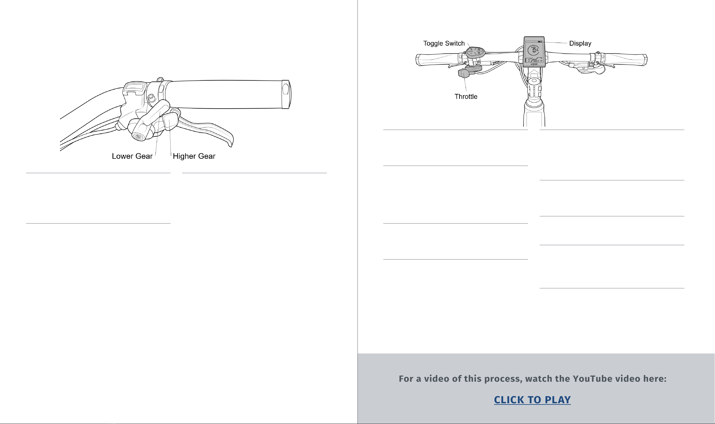
4 .5 Place the center of the handlebar in
the stem with the Espin logo on the dis-
play facing the rider. Put the faceplate
back into place over the handlebar,
as shown in Figure 11. There is no top
or bottom side of the faceplate. Make
sure there are no wires between the
faceplate, stem, or handlebar as these
can get pinched and damaged. When
riding the bike, the handlebar should be
angled so that your wrists are straight
when grabbing the brake levers.
Figure 10
Figure 11
10 11
Figure 7
Figure 8

UNSPOOK BRANDING DESIGN MANUAL
>> PAGE 13 // 44
UNSPOOK
BRANDING MATERIAL
CORPORATE DESIGN
AND GUIDELINES
For a video of this process, watch the YouTube video here:
CLICK TO PLAY
•Before every ride, it is very important to check the tire pressures. Too low of a tire pressure
will make pedaling more dicult, decrease range, and can cause pinch flats. The recommended
pressure range is printed on the drive side of every tire, so make sure to check the label on the
tire before inflating it. When removing the bike from the packaging, the tires will be at too low
of a pressure to ride safely. This is because the bike will have been inside the box for at least a
month before being delivered, and in this time the tire pressure will slowly decrease.
•The Nero and Nesta come with 26” x 4.0” and 20” x 4.0” tires respectively. These might not in-
clude a pressure range printed on the side, and instead just say 20PSI. We recommend 20PSI for
paved surfaces, 15PSI for hard dirt trails, and 10PSI for snow, sand, or soft dirt/mud.
•Make sure to check the tire pressures about once a week. Although tires may seem air tight,
the rubber is still a semi-permeable membrane that will slowly let air molecules through. This is
why bicycles have flat tires after being left alone for a couple months. If a tire goes flat overnight
however, the inner tube has a slow leak that will either need to be patched or replaced.
•All Espin bikes use tires with schrader valve inner tubes. Do not use tubes with presta valves.
The rims are not compatible with tubeless tires. Espin uses tires with the standard level of
puncture protection, but for maximum puncture protection, we recommend using either Tannus
Armour Inserts or Mr. Tuy Tire Liners. Check your tire size and the charts on their websites to
see which sizes to get. To maximize traction in icy winter conditions, there are options available
in most tire sizes for studded tires. For specific recommendations for which winter tires will work
with your model, contact our tech team at hello@espinbikes.com.
5INSTALL THE PEDALS
5 .1 Remove the pedals from the parts box.
One is labeled R for right (drive side) and the
other is labeled L for left (non-drive side). The
left pedal is threaded opposite from all the
other bolts, READ THESE INSTRUCTIONS THOR-
OUGHLY!
5 .2 The right pedal is threaded normal-
ly. Thread it into the crank arm clockwise.
Once it is threaded in a couple turns, it can
be quickly threaded in the rest of the way by
holding the flats of the pedal axle with the
provided tool and pedaling backwards, as
shown in Figure 14. Tighten this well.
5 .3 The left pedal has left-hand threading,
meaning it threads COUNTER-CLOCKWISE.
Once it is threaded in a couple turns, it can
be quickly threaded in the rest of the way by
holding the flats of the pedal axle with the
provided tool and pedaling backwards, as
shown in Figure 15. Tighten this well.
Figure 14 Figure 15
12
5 .4 Using the wrench to thread in the pedals
is just a tip for threading them in quickly. The
wrench is only necessary for the final tight-
ening of the pedals. The pedals should be
able to be threaded in all the way with just
your fingers. If screwing the pedals in be-
comes too hard after just a couple turns, STOP
and make sure that the pedals aren‘t getting
cross-threaded. If the pedal isn‘t threaded in
completely straight, the threads of the pedal
and crank arm could be getting damaged.
6INFLATE THE TIRES
13

UNSPOOK BRANDING DESIGN MANUAL
>> PAGE 15 // 44
UNSPOOK
BRANDING MATERIAL
CORPORATE DESIGN
AND GUIDELINES
>> PAGE 14 // 36
UNSPOOK BRANDING DESIGN MANUAL
•Remove the packaging from the seatpost and saddle.
•Make sure the seatpost collar is loose, then insert the seatpost into the seat tube.
•If the seatpost collar has a lever, that operates the same as the quick release skewer for the
front wheel. Hold the lever open 90°, make the adjustment nut finger tight, then close the lever
pointing forwards, so it is parallel with the seatpost collar.
•If the seatpost collar only has a hex bolt, that can be tightened with the provided hex wrenches.
Make sure that the gap in the seatpost collar is lined up with the gap in the seat tube.
•The saddle angle and position can be adjusted by loosening the large hex bolt directly under-
neath the saddle, where the seatpost clamps onto the saddle rails. A good starting point for
making saddle adjustments is to have the saddle angle flat, and the saddle clamp in the middle
of the rails. From there most riders like to angle the saddle down a bit and move the saddle fur-
ther forward.
•To adjust the saddle height, stand next to the bike and raise the saddle up to hip level. When
seated on the saddle and pedaling, the balls of your feet should be in the center of the pedal. At
the bottom of the pedal stroke, your leg should be almost fully extended but still slightly bent.
With correct saddle height, you should NOT be able to rest your feet flat on the ground while
seated. This would indicate too low of a saddle height and can cause knee damage. You should
only be able to touch the ground with your toes while seated. When stopping on a bicycle, you
will always need to stand up o the saddle until you start going again.
8 .3 The front light also mounts to the back of
the fork bridge when not using a front rack, as
shown in Figure 16.
8 .5 When mounting the front rack, make sure
that the provided spacers are between the
rack and the frame mounts to provide space
for the cables to be routed behind the rack.
After the front rack is mounted, turn the han-
dlebar all the way left and all the way right
and check to see if any of the cables are get-
ting caught. There should be enough range of
motion for the suspension caps or the brake
levers to touch the frame. If there is too
much tension on the cables for this to happen
easily, the cables will need to be moved to a
better position, either to the left or right side
of the rack mounts.
Figure 17
8 .4 When using a front rack, the front light
must be mounted to the underside of the rack
as shown in Figure 17. If the light is mounted
to the fork, the suspension travel will ram the
light up into the rack and damage the light.
8FRONT FENDER, FRONT RACK, AND
FRONT LIGHT INSTALLATION
8 .1 Our bikes come with the front fender, front
light, and front rack removed for safer ship-
ping.
Figure 16
8 .2 The front fender mounts onto the fork
using the supplied bolts, nuts, and washers.
The two metal arms of the fender attach to
the sides of the fork dropouts. The metal tab
at the top of the fender mounts to the back of
the fork bridge. The hole in this tab is an oval.
When fastening the bolt for this tab, make
sure that the fender is as high in the oval as it
will go to provide maximum clearance be-
tween the tire and the fender. If the fender is
too low, leaves and other debris can get stuck
in the fender.
7INSTALL THE SADDLE AND ADJUST
THE SADDLE HEIGHT
14 15

UNSPOOK BRANDING DESIGN MANUAL
>> PAGE 17 // 44
UNSPOOK
BRANDING MATERIAL
CORPORATE DESIGN
AND GUIDELINES
>> PAGE 16 // 36
UNSPOOK BRANDING DESIGN MANUAL
9 ADJUSTING STEM ANGLE
9 .2 Your stem might not have the bolt under
the stem shown in Figure 19. If it doesn’t, set
the stem to the desired angle and then tighten
the joint bolt. If your stem has the bolt shown
in Figure 19, then loosen this bolt until the
stem angle can be changed.
9 .1 The Nesta does not have an adjustable
angle stem. Proceed to 11. To adjust your
stem angle, first loosen the left side bolt on
the stem joint, as shown in Figure 28. The bolt
on the right does not need to be loosened. If
your stem only has one bolt on the joint, then
loosen that bolt until the stem can be rotated.
Figure 18
Figure 19
9 .3 Set the stem to the desired angle. To
ensure the silver plate under the bottom bolt
engages with the teeth in the joint, press up-
wards on the plate while rotating the stem so
that the engagement can be felt. The arrow in
Figure 19 shows where to press on the plate.
While still pressing on the plate, tighten the
bottom bolt to secure the plate. Then, tighten
the left side joint bolt. Recommended torque
is printed by the bolts.
9 .4 After setting the stem angle, the handle-
bar angle will need to be adjusted to compen-
sate for the change in stem angle. Loosen the
4 faceplate bolts until the handlebar can be
rotated. Get on the bike as if you are riding it
and adjust the handlebar angle so that your
wrists are straight when grabbing the brake
levers. Make sure the handlebar is centered
on the stem and tighten the 4 faceplate bolts
using the X pattern discussed in the handlebar
installation section.
For a video of this process, watch the YouTube video here:
CLICK TO PLAY
10 ADJUSTING THE SUSPENSION
FORK
• The Sport, Flow, Nero, and Nesta all come with the same type of suspension fork. It has a black
lockout lever on the top of the right side, and a clear yellow cap labeled PRELOAD on the top of
the left side.
• The PRELOAD cap is actually a rebound adjuster. To make rebound slower for slow speed o
road riding, turn the cap clockwise. To make rebound faster for going over bumps at high speeds,
turn the cap counter-clockwise. Turning the cap all the way counter-clockwise will make the fork
feel like a pogo stick. We recommend leaving this cap in a middle setting, which should work fine
for most conditions.
• The lockout lever can only be rotated a quarter turn, either to closed or open. Set to open, the
fork will have suspension. Set to closed, the suspension will be locked out. Locking out the sus-
pension is recommended for flat, paved terrain and especially for climbing hills. When riding o
road or going downhill, the lockout can be left open to take advantage of the suspension.
16 17

11 .1 The shifter is located on the right side
of the handlebar and has 2 levers, shown in
Figure 20. DO NOT shift the bike unless pedal-
ing, this can damage the shift line. Only shift
while pedaling.
11 .2 The high gear lever shifts the derailleur
into higher gears (smaller cogs). Pressing it
forward will make it click once and shift the
derailleur into a higher gear. If pedaling feels
too fast or easy, shift into a higher gear.
11 .3 The low gear lever shifts the derailleur
into lower gears (larger cogs). This lever has
a larger range of motion than the high gear
lever, and pressing it all the way forward will
make it click multiple times. Each click signi-
fies one lower gear. This larger range helps to
quickly shift into a lower gear if a hill is sud-
denly encountered. If pedaling feels too slow
or dicult, shift into a lower gear.
Figure 20
11 .4 The electrical controls are located on the
left side of the handlebar, and are highlighted
in Figure 21.
11 .5 The throttle is used for instantaneous
power, and the toggle switch is used to select
PAS levels, turn the lights on or o, activate
walk mode, turn on the USB charger, and
toggle through all of the display options and
settings.
11 .6 The display shows current speed, dis-
tance traveled, battery level, PAS level, and all
of the bike’s functions and settings.
11 .7 To turn the bike on, make sure the battery
is connected, locked, and turned on, then hold
the power button (I/O) on the toggle switch for
one second. When turning the bike on, it will
start in PAS 1. This is the slowest PAS level.
To select faster PAS levels, press the + button.
The fastest speed is PAS 5. For slower speeds
or to turn the PAS o with PAS 0, press the -
button.
11 .8 Whether using the throttle or PAS, the
motor can be instantly shut o by squeezing
either of the brake levers. The brake levers
have integrated motor cuto switches, the
wires for which come out of the lever next to
the brake line.
11 .9 To activate walk mode for walking the
bike uphill or up stairs, hold the - button. The
motor will kick in after a second and will keep
providing power until the - button is released.
11 .10 To turn the lights on, hold the + button
for one second. To turn the lights o, also
hold the + button for one second.
11 .11 To turn on the USB charging port, hold
the M button for one second. To turn it o,
also hold the M button for one second. The
USB port is on the front side of the display,
covered by a rubber cap.
For a video of this process, watch the YouTube video here:
CLICK TO PLAY
Figure 21
11 .12 To turn the bike o, hold the power but-
ton for one second. If the bike is not moving
and receiving no user inputs for 5 minutes, it
will automatically turn o. When o the bike
or walking it, ALWAYS either turn it o or set
to PAS 0.
11 HOW TO SHIFT GEARS AND OPERATE THE
PEDAL ASSIST SYSTEM (PAS)
18 19

UNSPOOK BRANDING DESIGN MANUAL
>> PAGE 21 // 44
UNSPOOK
BRANDING MATERIAL
CORPORATE DESIGN
AND GUIDELINES
>> PAGE 20 // 36
UNSPOOK BRANDING DESIGN MANUAL
Before the first ride, please make sure the following are tight and secure:
All bolts on the stem and stem faceplate (DO NOT tighten the top cap bolt unless adjusting the
headset)
Seatpost Collar and Saddle Bolt
Front Wheel Axle Bolt or Quick Release
Pedals (right side/drive side clockwise, left side/non-drive side counter-clockwise)
Front Fender, Light, and Rack Bolts
All electronic plugs, including the motor cable plug behind the pedals, as well as the plugs by
the handlebar for the display, throttle, and brake motor cutos. All the plugs have arrows on the
male and female sides that should be aligned when plugged in.
There are two small screws on the derailleur that look like they are unscrewed partway. They
are limiting screws and are set as intended. DO NOT screw these in unless you have experience
adjusting bicycle derailleurs.
For the first test ride, please test the following at slow speeds with the power o and
while wearing a helmet:
•Brakes, rear and front separately, then together. Right brake is rear, left brake is front. When
squeezing the rear brake lever all the way, there should be enough braking force for the tire to
skid. Disc brakes might squeak for the first mile because of the fresh brake rotors and pads. If
the brakes continue squeaking or if there seems to be a lack of braking force, contact us at hel-
lo@espinbikes.com.
•While constantly pedaling, shift all the way from gear 1 to 8, then back to 1. Pedal several rev-
olutions for each gear. If the chain is making unusual noises, feels like it’s getting stuck on any
gears or skipping, contact us at hello@espinbikes.com.
•After ensuring operational brakes and smooth shifting, stand up o the saddle and pedal as
hard as you can! If the maximum rider pedaling force produces any rhythmic clicking or creaking
timal braking force and brake pad wear, always squeeze both brake levers at the same time with
equal force. Never lean forward when braking.
•Turn the power on. The Nero and Nesta will need the battery switched on before the display
can be turned on. Test the throttle without any pedaling. Then, without using the throttle and
while pedaling, test the Pedal Assist System starting with PAS 1, progressively moving to PAS 5.
As programmed, PAS 1 should be about 10mph, and PAS 5 should be about 25mph. There will be
a slight delay when the PAS turns on or o, but the throttle should be immediate. If there seem
to be any issues with the motorized performance or any unusual sounds coming from the motor,
contact us at hello@espinbikes.com.
•Before riding at night, test the front and rear lights by holding the + button to turn them on. If
either do not turn on, contact us at hello@espinbikes.com.
20
12 SAFETY CHECKS 13 TEST RIDE
21

UNSPOOK BRANDING DESIGN MANUAL
>> PAGE 23 // 44
UNSPOOK
BRANDING MATERIAL
CORPORATE DESIGN
AND GUIDELINES
•The most frequent maintenance necessary for a bicycle is to inflate the tires once a week and
to keep the chain clean and lubricated. We recommend any bicycle chain lube, but Tri-Flow can
be used for the chain and derailleur joints and pulleys. If the chain gets dirty or gunked up, good
chain cleaners are either isopropyl alcohol or Clean Streak. These can be sprayed directly onto
the chain and wiped clean with a rag or paper towel. Most bicycle shops oer complete drive-
train cleaning services.
•The main components of a bicycle that wear out are the tires, brake pads, chain, cassette,
shifting cable/housing, and brake fluid or brake cable/housing. If the bike is being ridden almost
every day, these will likely all need to be replaced about once a year. Most bicycle shops carry
replacement parts that will fit our bikes. Nesta tires and inner tubes can either be purchased
•All Espin bikes (except the Aero and some models before 2021) have hydraulic disc brakes. If
these brakes ever lose their stopping power, or if one lever feels squishier than the other, it
might be time for a brake bleed. Most bike shops offer this as a service. Our bikes have Zoom
hydraulic disc brakes and use mineral oil. DO NOT use DOT fluid. DO NOT get oil or grease on the
brake rotor or pads. This will ruin the brake pads.
•Other components that can wear out over a much longer period of time are the chainring, de-
railleur pulleys, spokes, suspension fork, saddle, handlebar grips, and all of the bearings includ-
ing those for the headset, bottom bracket, and hubs. All of these items will likely be fine for at
least 5 years.
•For e-bikes, the main component that can wear out is the battery. Espin batteries are rated to
maintain their charge capacity for at least 500 charge/discharge cycles. The hall sensor of the
hub motor can burn out, but this is a fairly rare occurrence and should always be brought up with
Espin at hello@espinbikes.com.
•If the bike gets dirty or dusty, it can be washed o like a regular bicycle. First, turn o the pow-
er at the display, and turn o the battery for the Nero and Nesta. Leave the battery attached to
maintain the water-tight seal over the connection. Use a hose on the mist or shower setting to
rinse o the bike. DO NOT use the jet setting or high-pressure flow on any bearings or electrical
components. The bike can be wiped o with a soft cloth or paper towels. Leave the bike outside
to dry completely before turning the bike back on.
15 .1 Occasionally your display might show one of the above error codes with an H next to it. This
generally happens because a plug somewhere is loose due to jostling during shipping or after a
crash while riding the bike.
15 .2 All of the plugs on the bike are round, water resistant plugs with two arrows pointing to-
wards each other to indicate proper alignment. The seam for the plug is between the two arrows,
and can just be pulled apart.
15 .3 The inside of the throttle plug is orange, the display plug green, and the motor cuto plugs
red. These 4 plugs are all located in front of the handlebar, and are in the middle of the cables
coming out of their respective components.
15 .4 The motor plug is underneath the non-drive side chain stay (refer to the bike diagram on
page 5). This plug has a metal ring on it that must be unscrewed before the plug can be pulled
apart. Espin models before 2021 did not have this ring, and can simply be pulled apart.
15 .5 The controller is located in the compartment between the pedals. To access this, remove
the panel on the non-drive side held in place with 4 bolts. All of the controller plugs and wires
are matched by color.
14 CARING FOR YOUR BIKE
22
15 ERROR CODES
23

CONTACT US:
HELLO@ESPINBIKES.COM
PHONE NUMBER :
888 2964550
Quick Start Guide
UNSPOOK BRANDING DESIGN MANUAL
>> PAGE 25 // 44
*SCRYPE
BRANDING MATERIAL
CORPORATE DESIGN
AND GUIDELINES
ISSUE 01
BRANDING
DESIGN MANUAL
>> PAGE 24 // 36
UNSPOOK BRANDING DESIGN MANUAL
16 .1 You can access most of the settings programmed into the controller through the display and
toggle switch. Some of these settings are welcome to be changed by the user, including P1, P2,
P3, and A3. Most of the other parameters should not be changed from the settings recommended
above, or else the bike might not function correctly or the circuitry could even get fried.
16 .2 To access the parameter menu, turn on the bike, then double tap the M button. Press the +
button to move from P1, to P2, P3, etc. To change a parameter, press the M button once while on
that parameter, then use the + or - buttons to adjust the value at the bottom of the display. Once
the value has been adjusted, press the M button once to enter the new value and to start mov-
ing to other parameters. Once the password section is reached, use the + and - buttons to input
1801 and press M to enter each value. After adjusting any necessary settings, double tap M to
escape the parameters menu or simply wait 30 seconds.
16 .3 To adjust the power output of the individual PAS levels, navigate to parameter A2. Then,
press and hold + and - together to get to the PAS adjustment menu. You will see 1 (Indicating PAS
1) set to 40 and blinking. This means that PAS 1 will give you 40% motor power, which will make
the bike go about 10mph. Press the + or - button to adjust this to the desired setting and hit M.
Then you will be on the parameter for PAS 2. Adjust PAS 2 to the desired setting and hit M. Do
this for 3, 4 & 5. Once you hit M after setting PAS 5 you will be brought back to the regular display
menu.
Note: Doing this will not change the value of A2. Pressing + and - together at the A2 screen will
safely navigate away from A2.
16 DISPLAY SETTINGS
24 25
This manual suits for next models
3
Table of contents
Other Espin Bicycle manuals