Espin Aero User manual

CONTACT US:
HELLO@ESPINBIKES.COM
PHONE NUMBER :
888 2964550
effortlessly electric
Quick Start Guide

UNSPOOK BRANDING DESIGN MANUAL
>> PAGE 3 // 44
*SCRYPE
BRANDING MATERIAL
CORPORATE DESIGN
AND GUIDELINES
ISSUE 01
BRANDING
DESIGN MANUAL
TABLE OF CONTENTS
1 | Taking the Bike Out of the Box ................ 04
2 | Charging the Battery ...................... 06
3 | Install the Front Wheel ..................... 08
4 | Install the Handlebar .......................10
5 | Install the Pedals ..........................12
6 | Inflate the Tires ...........................13
7 | Install the Saddle and Adjust the Saddle Height ....14
8 | Safety Checks.............................15
9 | Test Ride ................................16
10 | Caring for Your Bike ........................17
11 | Display Settings ...........................18
AERO
ASSEMBLY
GUIDE Thank you for your purchase, and welcome to the Espin family!
This guide will help you assemble, operate, maintain, and enjoy
your Espin for as long as possible. For any questions or issues
along the way, please reach out to us online or on the phone
and one of our e-bike experts will be glad to help!

UNSPOOK BRANDING DESIGN MANUAL
>> PAGE 5 // 44
*SCRYPE
BRANDING MATERIAL
CORPORATE DESIGN
AND GUIDELINES
ISSUE 01
BRANDING
DESIGN MANUAL
>> PAGE 4 // 36
UNSPOOK BRANDING DESIGN MANUAL
4 5
1TAKING THE BIKE OUT OF THE BOX
1 .4 Remove all packaging on the bike. Zip-
ties are easiest to remove with a pair of wire
cutters. Do not accidentally cut any cables,
hoses, or the zip-ties holding them in place.
While removing the packaging on the bike,
lean it up against something vertical. Do not
lie the bike down on its side. Please leave all
of the packaging inside the main box and hold
onto it for at least 14 days in case the bike
needs to be returned. Make sure to register
your bike at espinbikes.com/pages/espin-sup-
port. The primary purpose of this is to record
the frame number of your bike in case it gets
stolen. The frame number is stamped into the
metal on the front of the head tube.
1 .1 Open the top of the main box and remove
the parts box inside.
1 .2 The parts box checklist :
Bike manual
Pedals
Front and rear reflectors and their
mounting brackets
Charger
Multi-tool for assembling your bike
Quick release skewer for front wheel
1 .5 If present, remove the plastic insert
wedged in the front brake caliper by pulling
down on it gently until it slides out. This is
there to prevent the pads from clamping to-
gether accidentally.
1 .3 To remove the bike, lift the bike straight
up out of the box. Two people might be need-
ed for this. Remember, NEVER PLACE THE BOX
ON ITS SIDE. This can damage the derailleur
and other components.
1 .6 Remove the metal or plastic dummy axle
from the fork dropouts, where the front wheel
mounts. This is there to protect the fork arms
from damage during shipping. If the dummy
axle is metal, unscrew the nuts holding it on
with the provided tools. If it is plastic, it can
either be pushed out by hand or tapped out
with a hammer or any heavy tool.
The bike shown above is the 21 Sport. Look through this diagram and find the labeled parts on
your own bike. Other Espin models might not have a top tube, have the battery in a dierent lo-
cation, or have a dierent type of stem. The only part not labeled in this diagram or elsewhere in
the manual is the controller. The controller is the computer of the bike, and is located inside the
frame above the bottom bracket on all Espin models. All Espin frames are made of 6061 alumi-
num.
The Aero comes with a 350W motor and 6.8Ah battery, and has mechanical disc brakes and no de-
railleur. The chainring has 44 teeth and the cog has 16 teeth, giving an eective gear ratio of 2.75.
The spokes are all 13 gauge, thicker than normal bicycle spokes. If a replacement spoke is ever
needed, contact us at hello@espinbikes.com for recommendations on proper sizes and spoke
suppliers.

>> PAGE 6 // 36
UNSPOOK BRANDING DESIGN MANUAL
For a video of this process, watch the YouTube video here:
CLICK TO PLAY
2CHARGING THE BATTERY
2 .2 When the charger is plugged into the wall
and not the battery, the light on the charger
will be green. When the battery is plugged in
and charging, the light will be red. Once the
battery finishes charging, the light will turn
green again. Simply put, the red light indi-
cates a flow of electricity through the charger.
2 .1 To charge the Aero, plug the charger into
a wall outlet, then plug it into the battery’s
charging port on the lower left side of the
downtube.
6 7
2 .3 Charging an empty battery can take up to
7 hours. The battery has overcharge protec-
tion so it will stop charging as soon as it is
full. This means it can safely be left plugged
in overnight.
2 .4 While charging, leave the charger on a
smooth hard surface like wood or tile. The
charger may get fairly warm if left on carpet
or other insulating materials. When done
charging, always cover the charging port
with the rubber cap. If water goes into the
charging port, the battery will short out and
need to be replaced.
2 .5 To maximize battery life and capacity,
allow the battery to warm up to room tem-
perature before plugging it into the charger.
Charging a cold battery will deplete the capac-
ity. If the bike is not being used for several
months, plugging the battery into the charger
until it is full once a month will also help with
battery life.
>> PAGE 8 // 36
UNSPOOK BRANDING DESIGN MANUAL
For a video of this process, watch the YouTube video here:
CLICK TO PLAY
3INSTALL THE FRONT WHEEL
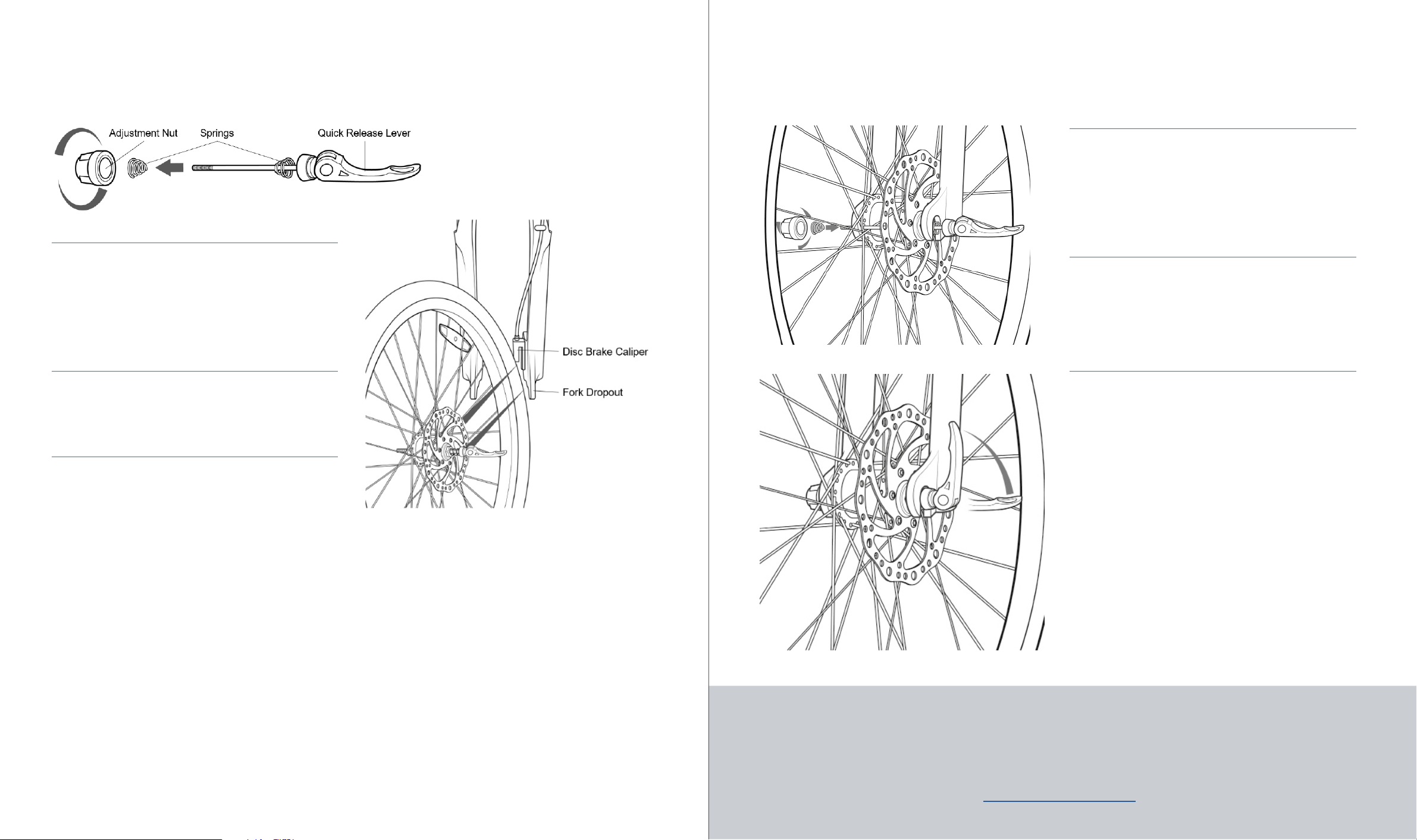
3 .1 Take the quick release skewer out of the
parts box and remove the adjustment nut and
spring on that side, as shown in Figure 1. Note
the spring orientation, it will need to go back
on with the small side facing inwards. There
are two springs, both have the small ends
facing inwards.
3 .3 With the rear wheel resting on the ground
and the bike upright, lift the front end of the
bike up and lower the fork onto the wheel so
that the disc brake rotor goes into the gap
in the disc brake caliper and the axle goes in
the fork dropouts. Rock the wheel side-to-
side to make sure the axles are all the way in
the dropouts. DO NOT FLIP THE BIKE UPSIDE
DOWN TO INSTALL THE WHEEL. This can put
too much weight on the display and other
components on the handlebar and damage
them. It is also best to use the bike’s weight
to ensure the axle is fully in the fork dropouts.
Once the front wheel is in, the kickstand can
be used to keep the bike upright.
3 .2 Insert the quick release skewer into the
front wheel axle so that the quick release le-
ver is on the same side as the disc brake rotor,
as shown in Figure 2.
Figure 2
8 9
Figure 3
3 .4 Once the wheel is in the fork, put the
spring back on the quick release skewer with
the small end facing inwards and thread the
adjustment nut back on. While holding the
quick release lever at 90° to the fork as shown
in Figure 3, screw the adjustment nut all the
way in until it is just finger tight.
3 .5 Close the quick release lever. The best
position for the lever is pointing upwards, as
shown in Figure 4. Make sure there is nothing
getting in the way of closing the quick release
lever all the way. If it is touching the fork or
brake, it might not be closed all the way.
Figure 1
Figure 4
3 .6 Lift the front wheel o the ground and
spin it. If the tire is rubbing the fork or the
disc brake rotor is rubbing the caliper, the
axle might not be fully in the fork dropouts.
Place the wheel back on the ground and open
the quick release lever. Rock the wheel side-
to-side by pushing the top of the wheel left
and right, until the axle clunks into the top of
the dropouts. Once the wheel is centered and
fully in the dropouts, close the quick release
lever and give the wheel another test spin. If
something is still rubbing, contact our tech
support agents at hello@espinbikes.com.

>> PAGE 10 // 36
UNSPOOK BRANDING DESIGN MANUAL
For a video of this process, watch the YouTube video here:
CLICK TO PLAY
4INSTALL THE HANDLEBAR 4 .4 To install the handlebar, first the
faceplate must be removed as shown in
Figure 8. Unscrew the 4 faceplate bolts
all the way, and be careful not to drop
them!
4 .6 Thread all 4 bolts back on, but only
halfway. When the faceplate is tight-
ened properly, there will be even gaps
on the top and bottom of the faceplate
as shown in Figure 10. To do this, thread
the top and bottom bolt on the left side
all the way in until the gaps are bal-
anced, but don’t tighten them. Once the
gaps are set, thread the other two bolts
all the way in without tightening them.
4 .7 When tightening the faceplate
bolts, they must be tightened in an X
pattern, similar to the star pattern used
when tightening the lug nuts on a car
wheel. As shown in Figure 11, tighten
1, 2, 3, and 4 in that order, one quar-
ter turn each. After one quarter turn
each, go back to bolt 1 and give them
all another quarter turn and repeat this
process until they are all evenly tight.
The torque for these bolts is 5 to 6Nm.
Figure 10
Figure 11
4 .1 If the bike arrived with the stem rotated
around as shown in Figure 5, the stem will
need to be rotated forwards. The stem on
some of our models may come pointing back-
wards to save space in the box. If the stem is
pointing forwards as shown in Figure 7, pro-
ceed to installing the handlebar in 4.4.
4 .2 To rotate the stem around, first loosen
the two bolts clamping the stem onto the
steerer tube, labeled in Figure 11. Once the
bolts are loose, brace the fork with your feet
or legs and rotate the stem around clockwise
as shown in Figure 6. After rotating the stem
around, if the fork seems harder to turn (tight
headset bearings), then the top cap bolt la-
beled in Figure 6 needs to be loosened. While
the two stem bolts are still loose, loosen the
top cap bolt one quarter turn. If the headset
bearings still feel tight, loosen the top cap
bolt one more quarter turn. The fork should
be able to rotate with little force.
Figure 7
4 .3 Once the top cap bolt is set and the stem
is pointing directly forwards, tighten the stem
bolts previously loosened in Figure 6. The
torque for these is 11 to 12Nm. These bolts
should be tightened progressively. Turn the
top one a quarter turn, then the bottom one a
quarter turn, then the top one etc. The stem
and fork should now be oriented as shown in
Figure 7.
For a video of this process, watch the YouTube video here:
CLICK TO PLAY
4 .5 Place the center of the handlebar
in the stem. Put the faceplate back into
place over the handlebar, as shown in
Figure 9. There is no top or bottom side
of the faceplate. Make sure there are
no wires between the faceplate, stem,
or handlebar as these can get pinched
and damaged. When riding the bike,
the handlebar should be angled so that
your wrists are straight when grabbing
the brake levers.
Figure 8
Figure 9
10 11
Figure 5
Figure 6

UNSPOOK BRANDING DESIGN MANUAL
>> PAGE 13 // 44
UNSPOOK
BRANDING MATERIAL
CORPORATE DESIGN
AND GUIDELINES
For a video of this process, watch the YouTube video here:
CLICK TO PLAY
•Before every ride, it is very important to check the tire pressures. Too low of a tire pressure
will make pedaling more dicult, decrease range, and can cause pinch flats. The recommended
pressure range is printed on the drive side of every tire, so make sure to check the label on the
tire before inflating it. When removing the bike from the packaging, the tires will be at too low
of a pressure to ride safely. This is because the bike will have been inside the box for at least a
month before being delivered, and in this time the tire pressure will slowly decrease.
•The Aero comes with 700 x 38c tires. Depending on the year and batch, the pressure should
be about 70PSI. A good rule to follow is to pump up bicycle tires to 5PSI below the max recom-
mended pressure printed on the tire. If the pressure range is 35PSI to 65PSI for example, the tire
should be pumped up to 60PSI. If riding in the rain or on o-road trails, it is a good idea to lower
the tire pressures closer to the minimum recommended pressure to maximize traction.
•Make sure to check the tire pressures about once a week. Although tires may seem air tight,
the rubber is still a semi-permeable membrane that will slowly let air molecules through. This is
why bicycles have flat tires after being left alone for a couple months. If a tire goes flat overnight
however, the inner tube has a slow leak that will either need to be patched or replaced.
•The Aero uses presta valve inner tubes. The rims are not compatible with tubeless tires. Espin
uses tires with the standard level of puncture protection, but for maximum puncture protection,
we recommend using either Tannus Armour Inserts or Mr. Tuy Tire Liners. Check your tire size
and the charts on their websites to see which sizes to get. To maximize traction in icy winter
conditions, there are options available in most tire sizes for studded tires. For specific recom-
mendations for which winter tires will work with your model, contact our tech team at hello@
espinbikes.com.
5INSTALL THE PEDALS
5 .1 Remove the pedals from the parts box.
One is labeled R for right (drive side) and the
other is labeled L for left (non-drive side). The
left pedal is threaded opposite from all the
other bolts, READ THESE INSTRUCTIONS THOR-
OUGHLY!
5 .2 The right pedal is threaded normal-
ly. Thread it into the crank arm clockwise.
Once it is threaded in a couple turns, it can
be quickly threaded in the rest of the way by
holding the flats of the pedal axle with the
provided tool and pedaling backwards, as
shown in Figure 12. Tighten this well.
5 .3 The left pedal has left-hand threading,
meaning it threads COUNTER-CLOCKWISE.
Once it is threaded in a couple turns, it can
be quickly threaded in the rest of the way by
holding the flats of the pedal axle with the
provided tool and pedaling backwards, as
shown in Figure 13. Tighten this well.
Figure 12 Figure 13
12
5 .4 Using the wrench to thread in the pedals
is just a tip for threading them in quickly. The
wrench is only necessary for the final tight-
ening of the pedals. The pedals should be
able to be threaded in all the way with just
your fingers. If screwing the pedals in be-
comes too hard after just a couple turns, STOP
and make sure that the pedals aren‘t getting
cross-threaded. If the pedal isn‘t threaded in
completely straight, the threads of the pedal
and crank arm could be getting damaged.
6INFLATE THE TIRES
13

UNSPOOK BRANDING DESIGN MANUAL
>> PAGE 15 // 44
UNSPOOK
BRANDING MATERIAL
CORPORATE DESIGN
AND GUIDELINES
>> PAGE 14 // 36
UNSPOOK BRANDING DESIGN MANUAL
•Remove the packaging from the seatpost and saddle.
•Make sure the seatpost collar is loose, then insert the seatpost into the seat tube.
•If the seatpost collar has a lever, that operates the same as the quick release skewer for the
front wheel. Hold the lever open 90°, make the adjustment nut finger tight, then close the lever
pointing forwards, so it is parallel with the seatpost collar.
•If the seatpost collar only has a hex bolt, that can be tightened with the provided hex wrenches.
Make sure that the gap in the seatpost collar is lined up with the gap in the seat tube.
•The saddle angle and position can be adjusted by loosening the large hex bolt directly under-
neath the saddle, where the seatpost clamps onto the saddle rails. A good starting point for
making saddle adjustments is to have the saddle angle flat, and the saddle clamp in the middle
of the rails. From there most riders like to angle the saddle down a bit and move the saddle fur-
ther forward.
•To adjust the saddle height, stand next to the bike and raise the saddle up to hip level. When
seated on the saddle and pedaling, the balls of your feet should be in the center of the pedal. At
the bottom of the pedal stroke, your leg should be almost fully extended but still slightly bent.
With correct saddle height, you should NOT be able to rest your feet flat on the ground while
seated. This would indicate too low of a saddle height and can cause knee damage. You should
only be able to touch the ground with your toes while seated. When stopping on a bicycle, you
will always need to stand up o the saddle until you start going again.
Before the first ride, please make sure the following are tight and secure:
All bolts on the stem and stem faceplate (DO NOT tighten the top cap bolt unless adjusting the
headset)
Seatpost Collar and Saddle Bolt
Front Wheel Axle Nut or Quick Release
Pedals (right side/drive side clockwise, left side/non-drive side counter-clockwise)
All electronic plugs, including the motor cable plug behind the pedals, as well as the plugs by
the handlebar for the display and brake motor cutos. All the plugs have arrows on the male and
female sides that should be aligned when plugged in.
7INSTALL THE SADDLE AND ADJUST
THE SADDLE HEIGHT
14 15
8SAFETY CHECKS

>> PAGE 16 // 36
UNSPOOK BRANDING DESIGN MANUAL
For the first test ride, please test the following at slow speeds with the power o and
while wearing a helmet:
•Brakes, rear and front separately, then together. Right brake is rear, left brake is front. When
squeezing the rear brake lever all the way, there should be enough braking force for the tire to
skid. Disc brakes might squeak for the first mile because of the fresh brake rotors and pads. If
the brakes continue squeaking or if there seems to be a lack of braking force, contact us at hel-
lo@espinbikes.com.
•After ensuring operational brakes, stand up o the saddle and pedal as hard as you can! If the
maximum rider pedaling force produces any rhythmic clicking or creaking sounds, contact us at
hello@espinbikes.com. Get a feel for the brakes when riding fast. For optimal braking force and
brake pad wear, always squeeze both brake levers at the same time with equal force. Never lean
forward when braking. Squeezing the front brake by itself too hard can cause the bicycle to tip
forward resulting in a crash.
•Turn the power on by holding the power button on the toggle switch for one second. While
pedaling, test the Pedal Assist System starting with PAS 1, progressively moving to PAS 3. As pro-
grammed, PAS 1 should be about 10mph, and PAS 3 should be about 20mph. There will be a slight
delay when the PAS turns on or o when the cadence sensor detects pedaling. If there seem to
be any issues with the motorized performance or any unusual sounds coming from the motor,
contact us at hello@espinbikes.com.
•The most frequent maintenance necessary for a bicycle is to inflate the tires once a week and to
keep the chain clean and lubricated. Any bicycle chain lube can be used, but most mechanics use
Tri-Flow. If the chain gets dirty or gunked up, good chain cleaners are either isopropyl alcohol or
Clean Streak. These can be sprayed directly onto the chain and wiped clean with a rag or paper
towel. Most bicycle shops oer complete drivetrain cleaning services.
•The main components of a bicycle that wear out are the tires, brake pads, chain, cassette, and
brake cable/housing. If the bike is being ridden almost every day, these will likely all need to be
replaced about once a year. Most bicycle shops carry replacement parts that will fit our bikes.
•Other components that can wear out over a much longer period of time are the chainring,
spokes, saddle, handlebar grips, and all of the bearings including those for the headset, bottom
bracket, and hubs. All of these items will likely be fine for at least 5 years.
•For e-bikes, the main component that can wear out is the battery. Espin batteries are rated to
maintain their charge capacity for at least 500 charge/discharge cycles. The hall sensor of the
hub motor can burn out, but this is a fairly rare occurrence and should always be brought up with
Espin at hello@espinbikes.com.
•If the bike gets dirty or dusty, it can be washed o like a regular bicycle. First, turn o the
power at the display, and make sure the charging port cover is in place. Use a hose on the mist
or shower setting to rinse o the bike. DO NOT use the jet setting or high-pressure flow on any
bearings or electrical components. The bike can be wiped o with a soft cloth or paper towels.
Leave the bike outside to dry completely before turning the bike back on.
9TEST RIDE
16
10 CARING FOR YOUR BIKE
17
CONTACT US:
HELLO@ESPINBIKES.COM
PHONE NUMBER :
888 2964550
Quick Start Guide
UNSPOOK BRANDING DESIGN MANUAL
>> PAGE 19 // 44
*SCRYPE
BRANDING MATERIAL
CORPORATE DESIGN
AND GUIDELINES
ISSUE 01
BRANDING
DESIGN MANUAL
>> PAGE 18 // 36
UNSPOOK BRANDING DESIGN MANUAL
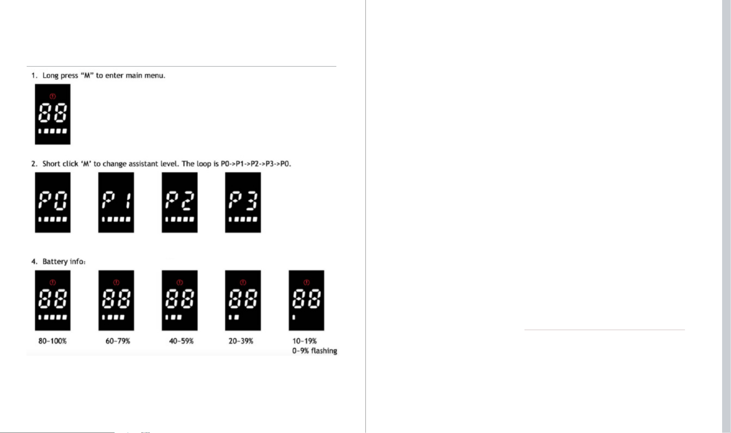
11 DISPLAY SETTINGS
18 19
Table of contents
Other Espin Bicycle manuals


