Esse-ti GSM500 M2M User manual

26/09/2017
User’s manual

Thanks for choosing
an Esse-ti product
This product has been especially designed for easy
operation. It has been manufactured with perfect
workmanship using suitable materials for long-lasting
performance.
All Esse-ti products are subjected to extensive reliability
and operational testing in our laboratories in order to
provide total guarantee for the user.
The User shall be responsible for defects arising from the use of the product. Esse-ti shall only be
responsible for defects according to and within the limitations set by the Presidential Decree dated
24/05/1988 no. 224 (fulfilling the EEC directive no. 85/374 on the harmonization of statutory and
administrative regulations of the Member States on the liability for damages arising from defective
products under art. 15 of Law no. 183 of 16 April 1987).
Esse-ti reserves the right to modify the product characteristics at any time without prior notice.

TABLE OF CONTENTS
GENERAL INSTALLATION INSTRUCTIONS .............................. 5
General Notes ................................................................................. 5
Making the installation ................................................................... 5
DESCRIPTION .................................................................................. 6
Features .................................................................................................... 6
LED .......................................................................................................... 7
INSTALLATION ............................................................................... 8
Inserting the SIM card ............................................................................. 9
Inserting the antenna ................................................................................ 9
Connections ............................................................................................ 10
Connection to the power supply ............................................................ 11
Turning the GSM500 M2M device on .................................................. 12
Device mounting operations .................................................................. 13
GSM500 M2M installation recommendations ...................................... 14
PROGRAMMING............................................................................ 15
Message format ...................................................................................... 15
Notification message format .................................................................. 16
SMS text setting ........................................................................... 17
Setting telephone number for notifications .................................. 17
Notification type setting ............................................................... 18
Setting telephone number for technological alerts ....................... 18
Battery check ............................................................................... 19
External power failure control ...................................................... 19
Relay command ........................................................................... 20
Setting the relay administrator telephone number ........................ 21
SIGNALS ......................................................................................... 22
LED .............................................................................................. 22
GSM signal indicator LED (GREEN) ................................................... 22
Device status indicator LED (RED) ...................................................... 22
Input status indicator LED (WHITE) .................................................... 23
Line status indicator LED (BLUE) ........................................................ 23
PROBLEM-DETECTION GUIDE .................................................. 24

EU DECLARATION OF CONFORMITY ...................................... 25

Page 5
GENERAL INSTALLATION
INSTRUCTIONS
GENERAL NOTES
Carefully read the notes contained in this section as they provide important
information on safe correct installation, use and maintenance of the product.
The product must be EXCLUSIVELY used for the purpose it was designed for.
Esse-ti shall not be responsible for damages arising from improper use.
The product has been designed in compliance with the regulations in force and
must be installed in systems that comply with the provisions of law.
Always disconnect power supply before performing internal or external operations
on the product (cleaning, maintenance, etc.).
Always refer to an authorized service centre for repair.
The device must be installed in a ventilated place, making sure that the ventilation
slots are never obstructed.
Do not install the product in environments with risk of explosion.
Make sure that the product has been installed as required.
Do not introduce objects, liquids or powders inside the product. Do not use sprays
inside the product.
Packing components (such as plastic bags, foam polystyrene, etc.) must be kept out
of the reach of children because potentially dangerous.
MAKING THE INSTALLATION
Internal telephone installations must be carried out by specialised personnel.
The installation and connection of telephone terminals to the telecommunications
network that do not comply with the regulations in force is not permitted.

Page 6
DESCRIPTION
GSM500 M2M
The GSM500 M2M allows to send an SMS or a CLI call (ring) to a
programmed telephone number when the specific input TEL is closed.
For correct operation, a GSM SIM card is required.
GSM500 M2M GC
The GSM500 M2M GC comes with built-in backup batteries and a relay
output which can be activated remotely via SMS or CLI call (ring).
Features
Remote programming via SMS
Closing input TEL signalling via SMS or CLI call (ring)
Battery check (model GC)
External power failure control (model GC)
SMS technological alerts (low-battery, dead battery, replaced battery,
external power failure/restore; model GC)
Relay activation via SMS or CLI call (model GC)
GSM signal indicator LED
Device status indicator LED
Input status indicator LED
Line status indicator LED
Quad Band GSM module
2 W transmission power
12 Vdc power supply input
230 Vac external adapter input
Input TEL (normally open)
Relay output (model GC)
External antenna (cable length = 2 m)
Back up battery (NiMH 800 mAh 7,2 V; model GC)
Page 7
External adapter (230 Vac 50 Hz input; 12 Vdc 500 mA output; CE
mark).
LED
The GSM500 M2M is equipped with 4 outer LEDs.
LEDs flashing is described at chapter “SIGNALS” (see page 22).
Green LED: GSM signal indicator LED
Red LED: Device status indicator LED
White LED: Input status indicator LED
Blue LED: Line status indicator LED
Page 8
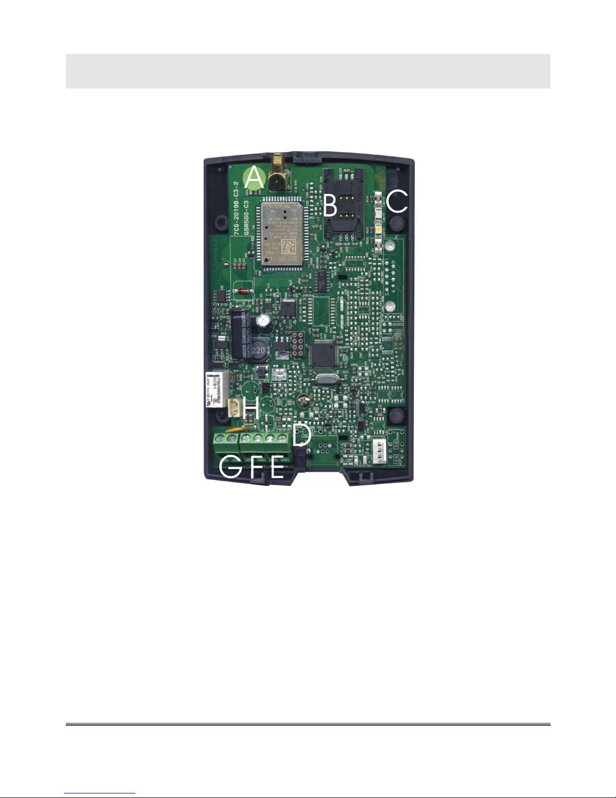
INSTALLATION
Remove the cover by pressing the upper side.
A ANTENNA cable connector
B SIM CARD housing with front panel
C LED indicating signal strength (green), LED indicating device status (red),
LED indicating input status (white) and LED indicating line status (blue)
D 230 Vac external adapter input
E TEL terminal block (normally open)
F 12Vdc power supply terminal block
G Relay terminal block (model GC)
H Backup battery connector (model GC)

Page 9
Inserting the SIM card
Before inserting or replacing the SIM card, always make sure that the
device has been disconnected from the mains and that no electrostatic
discharge is present in order to avoid damaging it.
Take all necessary measures to avoid electrostatic discharge.
Shift the SIM card housing cover downward until it unblocks and
lift it.
Carefully slide the SIM card into its housing cover.
Lower the SIM card housing cover and shift it upward until it
blocks.
WARNING
The SIM card PIN must be DISABLED. If the PIN is
enabled, it must be disabled through a mobile phone.
Inserting the antenna
Screw the antenna cable in to the connector on the top of the
module.
WARNING
NEVER connect the GSM500 M2M without having
previously installed the antenna. The device may get
damaged.
WARNING
Do not install the product near other electric or
electronic devices that were not especially designed to
be used with it. They could be subjected to RF
interference from the module.
Page 10
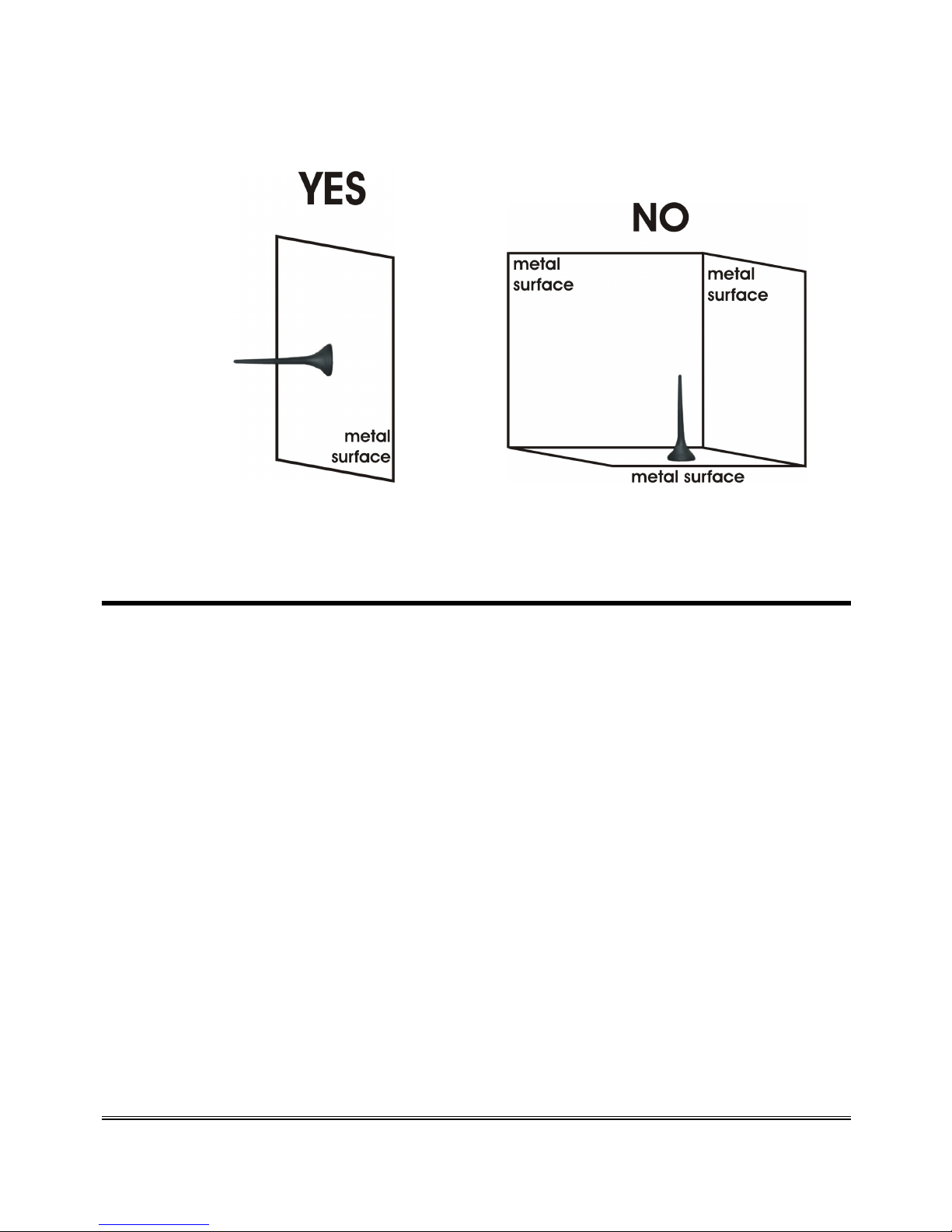
Position the antenna with magnetic base so that any metal
surfaces do not block the signal.
Connections
Connect the TEL terminal to a voltage free contact of an external
device.
Connect the RL terminal (if present and if necessary) to an external
device.

Page 11
Connection to the power supply
Power supply via 230Vac external adapter
Connect the external adapter to the specific input (D in the picture
at page 8.
Connect the backup batteries (if present) to the dedicated input (H
in the picture at page 8).
Close the device cover.
or
12Vdc power supply
Connect the power supply cable to the terminal (F in the picture at
page 8) taking care to respect the polarity.
Connect the backup batteries (if present) to the dedicated input (H
in the picture at page 8).
Close the device cover, paying attention to the power supply cable.
WARNING
The backup batteries, if present, may be connected only
after GSM500 M2M has been supplied.
Note: the max voltage to be supplied to the mains terminal F
is 17 Vdc.
Note: the min voltage required to supply the GSM500 M2M
device by the mains terminal F is 10 Vdc.
Note: a protection cut-out switch must be installed upstream
to interrupt power supply in case of fault.

Page 12
Turning the GSM500 M2M device on
Power the GSM500 M2M.
Wait 30 seconds after power-up to give time to the GSM500 M2M
to register correctly with the GSM network.
Make sure the red LED (device status) flashes briefly once every 3
seconds as shown in chapter “SIGNALS” (see page 22).
If the red LED flashes quicker and stays lit for a longer time (see page 22), the
GSM device has not properly registered with the GSM provider:
Disconnect GSM500 M2M and make sure the SIM card is inserted
correctly and that the PIN is not locking it.
See chapter “PROBLEM-DETECTION GUIDE” (page 24).

Page 13
Device mounting operations
Check the GSM signal strength through the green indicator LED
(see chapter “SIGNALS”, page 22) and identify an area where the
signal is strong enough.
Note: the signal strength may vary according to the
telephone provider.
Drill two holes with 5 mm diameter on the wall at a distance of 50
mm.
Insert the 2 wall plugs and screws down until the screws are at a 5
mm distance from the wall.
Place the GSM500 M2M device onto the two screws through the
two back slots.

Page 14
GSM500 M2M installation recommendations
The GSM500 M2M must be installed in a location where the radio
signal allows for using the GSM system.
It is advisable to leave plenty of space around the device for
maintenance operations.
Do not install the GSM500 M2M outdoors, since it lacks protection
devices against weather conditions that can damage the device (water,
humidity, etc.).
Do not install the GSM500 M2M near electronic (radio or TV sets,
Personal Computers, wired radio systems, etc.) or magnetic (credit
cards, etc.) devices that could be subjected to RF interference from the
module: recommended distance from the antenna is min. 2,5 m.
Do not install the GSM500 M2M near medical devices. Its operation
may cause damage to hearing aids or pacemakers.
Always make sure that the device operation is permitted in the place of
installation (e.g. installation is not allowed in hospitals, airplanes, etc.).
Page 15
PROGRAMMING
Programming via SMS is possible by any mobile phone or other device
supporting SMS. An SMS notifying that programming has been
completed will be sent back by the GSM500 M2M to the same telephone
number that forwarded the programming SMS.
WARNING
Programming outgoing SMS from the Internet may
not be successful if the requested format is not
respected.
When the GSM500 M2M sends or receives an SMS, the line status LED
(blue) will turn on.
Message format
Each programming SMS contains one or more programming commands.
The message format is required to be as follows:
Et-vm1 cmd par cmd par … cmd par
Where:
Et-vm1 : programming string start
cmd : programming command
par : parameter correlated to the command
Each command and each parameter must be separated by a space.
Example:
it is required to set the telephone number 0039333123123123.
Outgoing message text:
Et-vm1 alertphone 0039333123123123

Page 16
Notification message format
The format of the notification message is the same as the programming
message format.
SMS notifying an accepted command:
ET?VM1 cmd par
SMS notifying a rejected command:
ET?VM1 cmd ERROR
Example:
outgoing SMS to set the telephone number 0039333123123123.
Outgoing message text:
Et-vm1 alertphone 0039333123123123
Message text notifying accepted command:
ET?VM1 alertphone 0039333123123123

Page 17
SMS TEXT SETTING
It allows to customize the text of the SMS sent by the GSM500 M2M
when the input TEL is closed.
Et-vm1 message (customized text)
Command: message
Parameter: customized text enclosed in parentheses
max. 40 characters
Default: ALARM VENDING MACHINE
Example:
it is required to set the following text “Alarm: escalator n.12”
Outgoing message text:
Et-vm1 message (Alarm: escalator n.12)
Message text notifying accepted command:
ET?VM1 message (Alarm: escalator n.12)
SETTING TELEPHONE NUMBER FOR
NOTIFICATIONS
It allows to enter the telephone number appointed for SMS or CLI
notifications when the input TEL is closed.
Et-vm1 alertphone x…x
Command: alertphone
Parameter: telephone number with country code

Page 18
NOTIFICATION TYPE SETTING
It allows to set the type of notification (SMS or CLI call) when the input
TEL is closed.
SMS
Et-vm1 alertmode sms
CLI call
Et-vm1 alertmode call
Command: alertmode
Parameter: sms or call
Default: sms
Example:
it is required to set the notification via CLI call
Outgoing message text:
Et-vm1 alertmode call
Message text notifying accepted command:
ET?VM1 alertmode call
SETTING TELEPHONE NUMBER FOR
TECHNOLOGICAL ALERTS
It allows to enter the telephone number appointed for SMS alerts of low-
battery, dead battery, replaced battery, external power failure/restore
(only on model GC).
Et-vm1 techphone x…x
Command: techphone
Parameter: telephone number with country code

Page 19
BATTERY CHECK
It allows to activate the battery check (only on model GC).
When the charge of battery goes below the alert threshold, an SMS is sent
to the programmed telephone number for technological alerts with the
following text message: ALARM BATTERY LOW.
If the battery is found dead or damaged, an SMS is sent to the
programmed number with the following text message: ALARM
BATTERY BROKEN.
If the battery is absent or in case of disconnection, an SMS is sent to the
programmed number with the following text message: ALARM
BATTERY BROKEN.
When the battery is reconnected (or replaced, if found damaged), an SMS
is sent to the programmed number with the following text message:
ALARM BATTERY SUBSTITUED.
Activation
Et-vm1 battery on
Deactivation
Et-vm1 battery off
Command: battery
Parameter: on or off
Default: battery check disabled
EXTERNAL POWER FAILURE CONTROL
It allows to activate the external power failure control (only on model
GC).
If the external power failure lasts longer than the preset time interval, an
SMS is sent to the programmed telephone number for technological alerts
with the following text message: “ALARM POWER FAILURE”.

Page 20
If the external power supply is restored for a time interval equal to the
preset time interval, an SMS is sent to the programmed telephone number
with the following text message: “ALARM POWER RESTORED”.
Et-vm1 power yyzz
Command: power
Parameter: yy = from 01 to 99 minutes of lack of external power supply
zz = from 01 to 99 minutes of restored power supply
Default: external power failure control disabled
RELAY COMMAND
It allows to command the relay via SMS (only on model GC).
On
It allows to turn the relay on.
Et-vm1 relay on
Off
It allows to turn the relay off.
Et-vm1 relay off
Impulse
It allows to turn the relay on or off for a programmed amount of time.
Et-vm1 relay pulse yy
Command: relay pulse
Parameter: yy = from 01 to 99 seconds
Table of contents
Other Esse-ti Gateway manuals


