Esse-ti GSM500 User manual

7IS-80395 06/03/2020
User’s manual

TABLE OF CONTENTS
GENERAL INSTALLATION INSTRUCTIONS .............................. 4
General Notes ................................................................................. 4
Making the installation ................................................................... 4
DESCRIPTION .................................................................................. 5
Features .................................................................................................... 6
LED .......................................................................................................... 7
GSM500 hardware description ................................................................ 8
3G hardware description .......................................................................... 9
INSTALLATION ............................................................................. 10
Installation recommendations ................................................................ 10
EU declaration of conformity ................................................................ 10
Inserting the SIM card ........................................................................... 11
Inserting the antenna .............................................................................. 11
Connection to the telephone line ........................................................... 12
Connection to the power supply ............................................................ 12
Turning the gateway on ......................................................................... 13
Gateway mounting operations ............................................................... 14
GSM500 absorption chart ...................................................................... 15
3G absorption chart ................................................................................ 15
PROGRAMMING............................................................................ 16
Programming by telephone .......................................................... 16
(1) SIM card expiration check ................................................................. 21
(2) Battery check ...................................................................................... 22
(3) External power failure control............................................................ 22
(4) Relay-based notification of external power failure and/or mobile
network loss ........................................................................................... 23
(5) Automatic converter of selected telephone number........................... 23
Programming via SMS ................................................................. 26
Message format ...................................................................................... 26
Notification message format .................................................................. 28
SERVICES ....................................................................................... 30
Incoming calls .............................................................................. 30
Outgoing calls .............................................................................. 30
Measuring the signal level ........................................................... 31

Reading SIM card expiration ....................................................... 32
Reading the battery status ............................................................ 32
Activation relay ............................................................................ 33
SENDING SMS THROUGH DB-9 ................................................. 34
Sending received SMS text messages.................................................... 35
Sending SMS from device wired in the DB-9 connector ...................... 36
DATA TRANSMISSION ................................................................ 37
FEMALE DB-9 CONNECTOR ....................................................... 40
SIGNALS ......................................................................................... 41
Tones ............................................................................................ 41
Call signals ................................................................................... 42
LED .............................................................................................. 42
GSM/UMTS signal indicator LED (GREEN) ....................................... 42
Status indicator LED (RED) .................................................................. 43
Line status indicator LED / Data transmission indicator LED (WHITE)
................................................................................................................ 43
Power supply status indicator LED (BLUE) ......................................... 44
PROBLEM-DETECTION GUIDE .................................................. 45

Page 4
GENERAL INSTALLATION
INSTRUCTIONS
GENERAL NOTES
Carefully read the notes contained in this section as they provide important
information on safe correct installation, use and maintenance of the product.
The product must be EXCLUSIVELY used for the purpose it was designed for.
Esse-ti shall not be responsible for damages arising from improper use.
The product has been designed in compliance with the regulations in force and
must be installed in systems that comply with the provisions of law.
Always disconnect power supply before performing internal or external operations
on the product (cleaning, maintenance, etc.).
Always refer to an authorized service centre for repair.
The device must be installed in a ventilated place, making sure that the ventilation
slots are never obstructed.
Do not install the product in environments with risk of explosion.
Make sure that the product has been installed as required.
Do not introduce objects, liquids or powders inside the product. Do not use sprays
inside the product.
Packing components (such as plastic bags, foam polystyrene, etc.) must be kept out
of the reach of children because potentially dangerous.
MAKING THE INSTALLATION
Internal telephone installations must be carried out by specialised personnel.
The installation and connection of telephone terminals to the telecommunications
network that do not comply with the regulations in force is not permitted.

Page 5
DESCRIPTION
GSM500
GSM500 is a gateway that, connected to a fixed telephone or to the PSTN
input terminals of a PABX or autodialer, allows you to make and receive
calls over the GSM network. For correct operation, a GSM SIM card is
required.
GSM500 GC
The GSM500 GC gateway comes with built-in backup batteries.
GSM500 R2R
The GSM500 R2R gateway comes with built-in backup batteries and a
relay output which can be activated either locally or remotely via SMS.
GSM500.net
The GSM500.net gateway comes with built-in backup batteries and
female DB-9 connector for data transmission (through standard RS-
232/RS-485/CAN-bus) and SMS forwarding (through standard RS-
232/CAN-bus). For correct operation, a GSM (voice + data) SIM card is
required (GPRS data connection).
3G.next Voice
3G.next Voice is a gateway that, connected to a fixed telephone or to the
PSTN input terminals of a PABX or autodialer, allows you to make and
receive calls over the UMTS/GSM network. The 3G.next Voice gateway
comes with built-in backup batteries and a relay output which can be
activated either locally or remotely via SMS.
3G.next
The 3G.next gateway comes with a female DB-9 connector for data
transmission and SMS forwarding and a micro USB A/B port for direct
connection to the UMTS/GSM module (optional). For correct operation
the SIM card must be enabled for voice and data traffic.

Page 6
Features
Local programming via DTMF tones
Remote programming via SMS
Display of caller identification
Automatic country setting
CLIP / CLIR
Roaming setting
SIM card expiration check
Battery check (only available on models: GC, R2R, .net and 3G)
External power failure control (only available on models: GC, R2R,
.net and 3G)
Relay-based notification of external power failure (only available on
models: R2R and 3G)
Relay-based notification of GSM network loss (only available on
GSM500 R2R)
Relay-based notification of UMTS/GSM network loss (only
available on models: 3G)
SMS notifications (SIM card expiration, low-battery, dead battery,
replaced battery, external power failure/restore, GSM/UMTS
network restore)
Measurement of GSM/UMTS signal level
Automatic converter of selected telephone number
Receiver and transmitter gain adjustment
Remote reboot function
Data transmission through standard RS-232, RS-485 and CAN-bus
(only available on GSM500.net)
Data transmission through standard RS-232 and CAN-bus (optional
RS-485; only available on 3G.next)
Incoming text messages transmission towards devices wired in the
DB-9 connector under RS-232 standard (only available on
GSM500.net and 3G.next)

Page 7
Text messages transmission by devices wired into the DB-9
connector under RS-232 or CAN-bus standard (only available on
GSM500.net and 3G.next)
Remote firmware update
GSM/UMTS signal indicator LED
Status indicator LED
Line status indicator LED / Data transmission indicator LED (only
available on GSM500.net and 3G.next)
Power supply status indicator LED
Quad Band GSM module (GSM500 all versions)
Dual Band UMTS/GSM module (3G all versions)
2 W transmission power
12 Vdc power supply input
230 Vac external adapter input
Female DB-9 connector (only available on GSM500.net and 3G.next)
Micro USB A/B port (optional, only available on 3G.next)
Relay output (1 A, 24 V; only available on models: R2R and 3G)
External antenna (cable length = 2 m)
External adapter (230 Vac 50 Hz input; 12 Vdc 500 mA output; CE
mark; only available on models: GC, R2R, .net and 3G)
LED
The gateway is equipped with 4 outer LEDs.
LEDs flashing is described at chapter “SIGNALS” (see page 42).
Green LED: GSM/UMTS signal indicator LED
Red LED: Status indicator LED
/ White LED: Line status indicator LED / Data transmission
indicator LED (only available on GSM500.net and 3G.next)
Blue LED: Power supply status indicator LED
Page 8
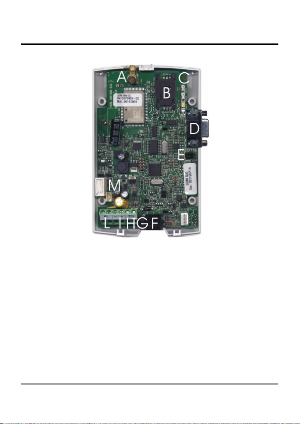
GSM500 hardware description
Remove the cover by pressing the upper side.
A ANTENNA cable connector
B SIM CARD housing with front panel
C LED indicating signal strength (green), LED indicating device operation status
(red), LED indicating line status / data transmission (white) and LED indicating
power supply status (blue)
D Female DB-9 connector (.net models only)
E Jumper (.net model only)
F Telephone line output (RJ11 connector) for telephone set connection or PABX
analogue line connection
G 230Vac external adapter input
H Telephone line output (terminal block) for connection of autodialer/PABX
analogue line
I 12Vdc power supply terminal block
L Relay terminal block (R2R model only)
M Backup battery connector (GC, R2R and .net models only)

Page 9
3G hardware description
Remove the cover by pressing the upper side.
A Micro USB A/B port (optional, 3G.next)
B ANTENNA cable connector
C SIM CARD housing with front panel
D LED indicating signal strength (green), LED indicating device operation status
(red), LED indicating line status / data transmission (white) and LED indicating
power supply status (blue)
E Female DB-9 connector (3G.next)
F RS-485 termination jumper (3G.next)
G CAN-bus termination jumper (3G.next)
H Telephone line output (RJ11 connector) for telephone set connection or
autodialer/PABX analogue line connection
I 230 Vac external adapter input
L Telephone line output (terminal block) for telephone set connection or
autodialer/PABX analogue line connection
M 12 Vdc power supply terminal block
N Relay terminal block
O Backup battery connector

Page 10
INSTALLATION
Installation recommendations
The gateway must be installed in a location where the radio signal
allows for using the GSM/UMTS system.
It is advisable to leave plenty of space around the gateway for
maintenance operations.
Do not install the gateway outdoors, since it lacks protection devices
against weather conditions that can damage the gateway (water,
humidity, etc.).
Do not install the gateway near electronic (radio or TV sets, Personal
Computers, wired radio systems, etc.) or magnetic (credit cards, floppy
disks, etc.) devices that could be subjected to RF interference from the
module: recommended distance from the antenna is min. 2,5 m.
Do not install the gateway near medical devices. Its operation may cause
damage to hearing aids or pacemakers.
Always make sure that the device operation is permitted in the place of
installation (e.g. installation is not allowed in hospitals, airplanes, etc.).
EU declaration of conformity
Hereby, Esse-ti S.r.l. declares that the equipment type GSM500/3G.next
is in compliance with Directive 2014/53/EU.
The full text of the EU declaration of conformity is available from the
following Internet address:
https://www.esse-ti.it/en/dichiarazioni-di-conformita

Page 11
Inserting the SIM card
Before inserting or replacing the SIM card, always make sure that the
gateway has been disconnected from the mains and that no electrostatic
discharge is present in order to avoid damaging it.
Take all necessary measures to avoid electrostatic discharge.
Shift the SIM card housing cover downward until it unblocks and
lift it.
Carefully slide the SIM card into its housing cover.
Lower the SIM card housing cover and shift it upward until it
blocks.
WARNING
The SIM card PIN must be DISABLED. If the PIN is
enabled, it must be disabled through a mobile phone.
Inserting the antenna
Screw the antenna cable in to the connector on the top of the
module.
WARNING
NEVER connect the gateway without having previously
installed the antenna. The gateway may get damaged.
WARNING
Do not install the product near other electric or
electronic devices that were not especially designed to
be used with it. They could be subjected to RF
interference from the module.
Position the antenna with magnetic base so that any metal
surfaces do not block the signal.

Page 12
Connection to the telephone line
Connect the gateway to a standard telephone or to the PSTN input
terminals of a PABX or autodialer via the RJ-11 connector (F in the
picture at page 8 / H in the picture at page 9);
or
Connect the gateway to a standard telephone or to the PSTN input
terminals of a PABX or autodialer using the TEL terminal (H in the
picture at page 8/ L in the picture at page 9).
Connection to the power supply
Power supply via 230 Vac external adapter
Connect the external adapter to the specific input (G in the picture
at page 8 / I in the picture at page 9).
Connect the backup batteries (if present) to the dedicated input (M
in the picture at page 8 / O in the picture at page 9).
Close the gateway cover.
or

Page 13
12 Vdc power supply
Connect the power supply cable to the specific terminal (I in the
picture at page 8 / M in the picture at page 9) taking care to
respect the polarity.
Connect the backup batteries (if present) to the dedicated input (M
in the picture at page 8 / O in the picture at page 9).
Close the gateway cover, paying attention to the power supply
cable.
WARNING
Backup batteries, if present, may be connected only
after gateway has been supplied
Note: the max voltage to be supplied to the 12 Vdc terminal
is 17 Vdc.
Note: the min voltage required to supply the gateway by the
12 Vdc terminal is 10 Vdc.
Note: a protection cut-out switch must be installed upstream
to interrupt power supply in case of fault.
Turning the gateway on
Power the gateway.
Wait 30 seconds after power-up to give time to the gateway to
register correctly with the GSM/UMTS network.
Make sure the red LED (device status) flashes briefly once every 3
seconds as shown in chapter “SIGNALS” (see page 43).
If the red LED flashes quicker and stays lit for a longer time (see page 43), the
gateway has not properly registered with the GSM/UMTS provider:
Disconnect the gateway and make sure the SIM card is inserted
correctly and that the PIN is not locking it.
See chapter “PROBLEM-DETECTION GUIDE” (page 45).

Page 14
Gateway mounting operations
Check the GSM/UMTS signal strength through the green indicator
LED (see chapter “SIGNALS”, page 42) and identify an area where
the signal is strong enough.
Note: the signal strength may vary according to the
telephone provider.
Drill two holes with 5 mm diameter on the wall at a distance of 50
mm.
Insert the 2 wall plugs and screws down until the screws are at a 5
mm distance from the wall.
Place the gateway onto the two screws through the two back slots.
Page 15
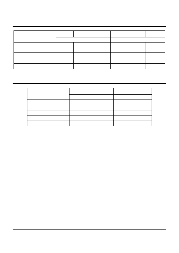
GSM500 absorption chart
Power supply 10Vdc 12Vdc 13,8Vdc 10Vdc 12Vdc 13,8Vdc
(battery not connected) (battery connected)
Telephone
handset down 30mA 30mA 25mA 40mA 60mA 50mA
Telephone handse
t
up 90m
A
80m
A
70m
A
100m
A
105m
A
90m
A
Conversation 130m
A
115m
A
110m
A
140m
A
135m
A
130m
A
Data transmission 75m
A
60m
A
55m
A
85m
A
80m
A
75m
A
3G absorption chart
Power supply 12
V
dc 12
V
dc
(battery not connected) (battery connected)
Telephone
handset down 40 mA 60 mA
Telephone handset up 80 m
A
100 m
A
Conversation 130 m
A
150 m
A
Data transmission 90 m
A
110 m
A

Page 16
PROGRAMMING
Programming can be carried out locally via a multi-frequency telephone
or remotely via SMS.
PROGRAMMING BY TELEPHONE
Connect a standard telephone to the gateway via the RJ-11
connector (F in the picture at page 8 / H in the picture at page 9)
or using the TEL terminals (H in the picture at page 8 / L in the
picture at page 9).
Lift the handset and dial the desired programming code (see table
“Programming by telephone”).
Note: at the end of each programming carried out correctly,
you will hear a confirmation tone, while an error tone
will be heard in case of error. In any case, the
dialling tone will follow, after which you can proceed
with the programming or make a call.
Note: during programming, the inter-digit dialling time must
not exceed 5 seconds (see the programming “Inter-
digit dialling time”). Once 5 seconds has elapsed
without digits you will hear the dissuasion tone and
you will have to wait the dialling tone or to hang up.
Note: programming can be carried out even if the signal is
absent. After the confirmation or the error tones, the
dissuasion tone will follow, after which you can
proceed with programming or hang up.
Note: in the table “Programming by telephone” factory
default values are highlighted in bold.

Page 17
PROGRAMMING BY TELEPHONE
TELEPHONE LINE
VOLTAGE
(TEL terminals
and RJ-11
connector)
**61*X#
X: option, from 0 to 1
0= 36 Vdc
1= 52 Vdc
USE MODE **2X#
X: option, from 1 to 4
1= default
2= mode recommended for autodialers or
other devices effecting tone detection
over the line
3= mode recommended to reduce echo
occurring during conversation
4= mode recommended to reduce echo in
case of connection with devices effecting
tone detection over the line
INTER-DIGIT
DIALLING TIME **8*X# X: seconds, from 1 to 9; 0=10 seconds
5 factory default
CLIP SETTING
**7*1*GGMMAA*HH
MM#
Enabling
GG: day, MM: month, AA: year;
HH: hour, MM: minutes
**7*0# Disabling
Default: disabled (call date and time not displayed on the display of the
connected telephone or device)
CLIR PERMANENT
SETTING **6*X#
X: option, from 0 to 2
0= the sending of your number to the
called user depends on the settings
of the telephone operator
1= your number is not sent to the called
user
2= your number is sent to the called user
CLIR TEMPORARY
SETTING
**16# Your number is not sent for a single call
**17# Your number is sent for a single call

Page 18
PROGRAMMING BY TELEPHONE
ROAMING
**5*1# Enabling
**5*0*XXXY...Y#
Disabling
XXX: MCC of your telephone operator
Y…Y: MNC of your telephone operator
(when roaming is disabled, in case the
gateway registers with a different provider
than the programmed, it is not possible to
make or receive any calls)
Default: roaming enabled
NOTIFICATION
TELEPHONE
NUMBER
**40*X…X*X…X#
X…X: telephone number appointed for SMS
notifications of SIM card expiration, external
power failure/restore, mobile network
restore, low-battery, dead battery, replaced
battery and for SMS reading SIM expiration
and battery status
**40# Deleting
ADMINISTRATOR
TELEPHONE
NUMBER
**18*X…X*X…X#
X…X: telephone number with country code
(if set, it is the only number from which
programming via SMS is allowed)
**18# Deleting
PROGRAMMING
PASSWORD **19*X…X*X…X # X…X: new password (max. 3 digits)
0 factory default
SIM CARD
EXPIRATION
CHECK (1)
**53*X…X#
Enabling
X…X: days before SIM expiration, from 1 to
330
**53*0# Disabling
Default: check disabled

Page 19
PROGRAMMING BY TELEPHONE
BATTERY
CHECK (2)
**5X#
X: option, from 0 to 1
0= check enabled
1= check disabled
**52*X#
X: option, from 0 to 7
0= 7 h
1= 6 h e 30’
2= 6 h
3= 5 h e 30’
4= 4 h
5= 2 h e 30’
6= 1 h e 30’
7= 1 h
(minimum number of operating hours, in idle
mode, guaranteed by the battery charge;
below this threshold, a notification SMS is
sent out)
EXTERNAL
POWER FAILURE
CONTROL (3)
**81*X# X: minutes of external power failure/restore,
from 3 to 9
**81*0# Disabling
Default: control disabled
RELAY SETTING **93*XX#
XX: op
t
ion, from 00 to 99
00= bistable output relay (you can activate
or deactivate the relay)
01-99= seconds of pulse duration (the relay
can execute a pulse of duration set)
01 factory default

Page 20
PROGRAMMING BY TELEPHONE
RELAY-BASED
NOTIFICATION
OF EXTERNAL
POWER FAILURE
AND/OR MOBILE
NETWORK
LOSS (4)
**94*X#
X: op
t
ion, from 0 to 6
0= notifications disabled
1= the relay is deactivated in case of
external power failure
2= the relay is deactivated in case of mobile
network loss
3= the relay is deactivated in case of
external power failure or in case of
mobile network loss
4= the relay is activated in case of external
power failure
5= the relay is activated in case of mobile
network loss
6= the relay is activated in case of external
power failure or in case of mobile
network loss
AUTOMATIC
CONVERTER OF
DIALED
TELEPHONE
NUMBER (5)
**26*X…X*Y*Z…
Z*Z…Z#
ENTERING NUMBERS TO CALL
X…X: programming password
Y: table position, from 1 to 5
Z…Z: telephone number
**26*X…X*Y#
DELETING NUMBER TO CALL
X…X: programming password
Y: table position, from 1 to 5
**26*X…X*# DELETING ALL NUMBERS TO CALL
X…X: programming password
**25*X…X*Y*Z…
Z*Z…Z#
ENTERING DIALED NUMBERS
X…X: programming password
Y: table position, from 1 to 5
Z…Z: telephone number
**25*X…X*Y#
DELETING DIALED NUMBER
X…X: programming password
Y: table position, from 1 to 5
**25*X…X*# DELETING ALL DIALED NUMBERS
X…X: programming password
Other manuals for GSM500
1
Table of contents
Other Esse-ti Gateway manuals


Popular Gateway manuals by other brands


Digi
Digi X2E-Z1C-W1-A quick start guide

BFT
BFT B EBA BLUE GATEWAY installation manual

Digi
Digi Smart quick start guide

Patton electronics
Patton electronics SMARTNODE 1200 Getting started guide

Moxa Technologies
Moxa Technologies MRC-1002 Series Quick installation guide

RTA
RTA 460PSMC-NNA1 Product user guide

maxon motor
maxon motor EPOS4 Module 50/8 manual

FieldServer
FieldServer ProtoNode RER Installation & operating instructions

Option Audio
Option Audio Globe surfer II user guide

Viola Systems
Viola Systems Arctic 3G Gateway 2622 quick start guide

Generex
Generex BNC2 quick start guide

URC
URC MX HomePro Integration guide