Tofindacauseinacasewhenthesystemjustwon'tstart,it'sbesttobeginwiththesimplest
ofprobablereasonsandworkingyourwaytothemoretimeconsuming/complexones,eg.it's
besttocheckifthepowerstripisonbeforechangingtheRAM.
SYSTEM WON'T START, NO VIDEO.
Aftermakingsuretheethernetcableworks,proceedtocheckingifthegrayethernetcable
labeledingrayas“6”isfirmlyconnectedonboththemotherboardandthesystems
controller.Ifthisdoesn’tsolvetheissueseeiftheportontherearofthemachineworks.
THE MACHINE CAN’T CONNECT TO THE INTERNET
EachMinerDudeistestedbeforeshipping.Issueswiththebootmediaaremostlikely
shippingrelatedorcanhappenwhentheSATAcablegetsdisturbedduringinitialsetup.If
thebootdriveisnotdetected,trydisconnectingandconnectingthedrive.Incasethat
doesn'thelp,makesurethatbothoftheSATAcableconnectorsaresecurelyfastened.Ifthe
machineisstillbootingintothebiosscreen,reconnectthesatacabletoadifferentSATA
headeronthemotherboard.
SSD
SYSTEM WON'T START, NO VIDEO.
MakesureeachpowersupplyisinsertedproperlyandthestatusLEDisworking.
Ifthesystemkeepscrashing,removeallbutonepowersupplyandremoveallbutoneGPU.
Ifyou’restillfacingthesameissue,replacethatsinglepowersupplyandreplacethe
graphicscardwithadifferentone.
ReseatRAMintoanotherslot,makesureit'sproperlyseated.
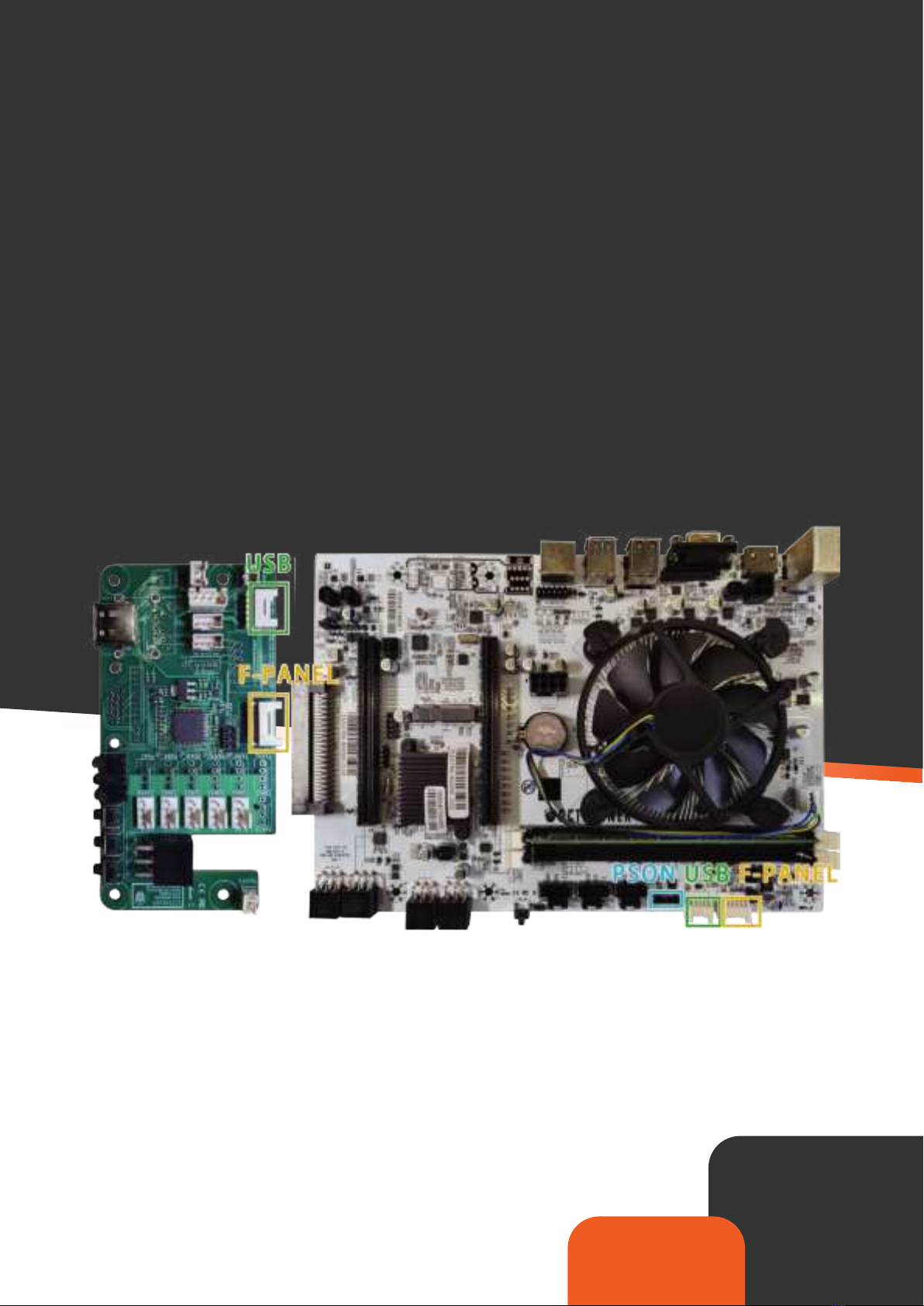
UnplugtheSystemsControllerPCIecable,disablingthefans.
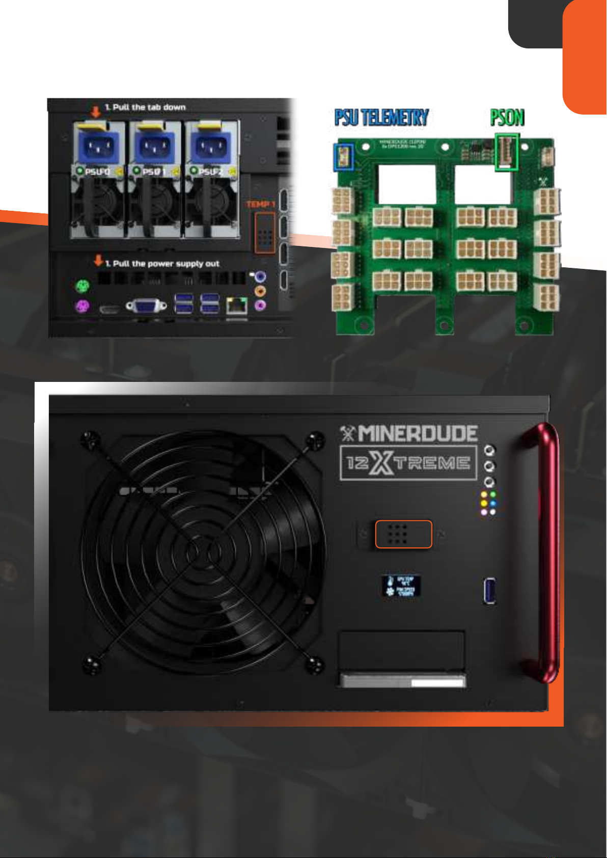
MakesurethepowersupplyLED'sareon.Ifnot,makesurethepowersupplyisfully
inserted.Trywithjustonepowersupplyfirst.
IsthePSONcableconnectorfirmlyfastenedonthemotherboardandthepower
supplybackplane?Themotherboardisresponsibleforturningonthepowerdelivery.If
the6-pincableconnectingthepowersupplybackplaneandthemotherboardisnot
securelyconnected,thesystemwon'tturnon.
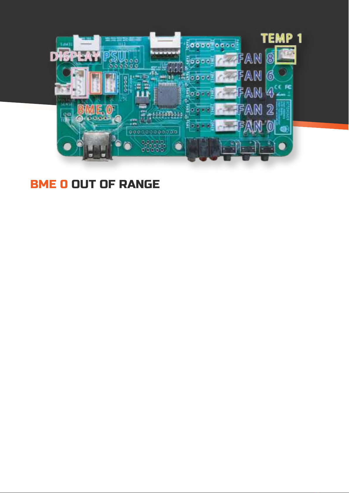
ArethestatusLED'sonthefrontpanelworking?TheSystemsControllerispoweredby
themotherboard.
CheckiftheCPUfanisspinning.Ifnot,pressthepowerbuttononthefrontpanelorthe
oneonthemotherboard.
DidyouconnectVGAproperly?Isthemonitorpowered?