Swagelok RHPS Series User manual

RHPS Series
BD(H)10, 15 (-DP)
User Manual
Read the complete manual before installing and using the regulator.

2
Contents
Introduction ............................................................................................................................................... 3
Installation ................................................................................................................................................. 5
Operation ................................................................................................................................................... 8
Maintenance .............................................................................................................................................. 9
Troubleshooting ...................................................................................................................................... 11
WARNING
Before removing a regulator from the system for service, you must
▪ depressurize system
▪ purge the system to remove any residual system media left in the regulator.

3
Introduction
Representative drawing of the standard BDH10/BDH15
1 body 14 diaphragm
2 dome 15 dome plate
3 body plug 16 O-ring
4 dome ring 18 O-ring
6 valve assembly 19 O-ring
9 seat 25 socket head cap screw
10 overtravel spring 27 ring
11 diaphragm plate 28 ring
12 dome spring 29 nut
13 retaining screw

4
Representative drawing of the standard BDH10/BDH15(-DP)
2 Dome
4 Dome screw
8 Spring guide
12 Set spring
14 Diaphragm
15 Bottom spring guide
20 O-ring
21 O-ring
25 Socket head cap screw
28 Nut
30 Retaining ring
36 Set screw

5
Installation
WARNING
Self-venting and captured-venting regulators can release system fluid to atmosphere.
Position the self-vent hole or the captured vent connection away from operating
personnel.
CAUTION
Do not use the regulator as a shutoff device.
When using the BDH10,15 -DP with inlet pressure higher than 3335 psig (230 bar), a
safety valve must be installed in the outlet line, because the outlet pressure may not
exceed 3335 psig (230 bar).
The standard maximum in- and outlet pressure for the models are:
Threaded models BD10,15 : Inlet 70 bar Outlet 70 bar
Threaded models BDH10,15 : Inlet 250 bar Outlet 250 bar
Threaded models BDH10,15 -DP : Inlet 250 bar Outlet 230 bar
Flanged models BD(H)10,15 : Inlet flange rating Outlet flange rating
Connections to System
The preferred mounting position of the regulator is horizontal with the dome facing upwards.
The standard connection of the BD(H)10 is 1 in. female BSPP.
The standard connection of the BD(H)15 is 1 ½ in. female BSPP.
To get a proper seal across the thread, Swagelok recommends using bonded seal rings.
If grounding is required, connect a ground wire under a dome bolt.

6
Filling the dome
The dome can be filled in different ways.
1. This can be done by taking the gas or liquid pressure from the system and feeding this through
a needle valve or fixed orifice into the dome.
A spring loaded back pressure regulator controls the dome pressure. The outlet pressure from
the pilot regulator could be vented to the atmosphere or into the outlet line.
This is shown in sketch A.
2. The pressure in the dome can also be controlled with an external pressure source. The gas
pressure can be taken from a cylinder or shop air mains.
A spring loaded pressure regulator controls the dome pressure. The regulator works best with a
continuous bleed on the dome.
This is shown in sketch B.
CAUTION
It is not recommended to place a gauge on the dome to check the set pressure.
Because of forces in the regulator, the dome pressure will always be lower than the
inlet pressure. Place a gauge in the inlet line to check the set pressure.
Sketch A Sketch B
External feedback
CAUTION
When using the regulator with external feedback, option –EF, make sure that the outlet
pressure can be fed back to the external feedback connection before applying
pressure to the regulator. Failing to do so may lead to damage and non-functioning of
the regulator as the inlet pressure will be put straight through to the outlet.
The purpose of the external feedback on a pressure regulator is to get a more accurate regulation of
the outlet pressure. This can be achieved by sensing the outlet pressure downstream of the regulator
and feeding it back to the regulator. For this purpose Swagelok has provided a special connection,
marked on the regulator itself as "external feedback".

7
Connecting the external feedback
The external feedback must be installed as follows:
▪ The external feedback is to be connected in a turbulence-free zone in the downstream piping,
at a maximum distance of 5 the outside diameter of the down stream piping.
▪ The external feedback must be connected on top of the downstream piping.
CAUTION
Never connect the external feedback line downstream of a shut-off valve.
Principle sketch of external feedback:

8
Operation
CAUTION
When using the BDH10,15 -DP with inlet pressure higher than 3335 psig (230 bar), a
safety valve must be installed in the outlet line, because the outlet pressure may not
exceed 3335 psig (230 bar).
Note: For changing the differential set pressure on a -DP regulator, an “open end wrench 15 mm” is
required. For changing the set pressure on a standard regulator, no tools are required.
▪ Inlet and set pressure settings are obtained by adjusting pressure in the dome.
▪ Increase the pressure in the dome to increase the inlet pressure.
▪ Decrease the pressure in the dome to decrease the inlet pressure.
▪ Icing of the regulator at high flow rates or high pressure drops may occur if the gaseous media or
atmosphere contains moisture.
▪ An auxiliary upstream filter is recommended for use in all but the cleanest of media.
▪ After flow, the inlet pressure will fall a little under the set pressure.
This is because of the closing force required for bubble-tight closing of the regulator.
This phenomenon is usually referred to as the “reseat pressure” and does not indicate a problem
with the regulator.
▪ An increase in the flow will result in a rise of the set pressure.
A decrease in the flow will result in a fall of the set pressure.
This is because of the force required for opening the valve of the regulator.
This phenomenon is usually referred to as the “accumulation pressure” and does not indicate a
problem with the regulator.
▪ An increase of the outlet pressure will result in a fall of the set pressure.
A decrease of the outlet pressure will result in a rise of the set pressure.
This phenomenon is usually referred to as the “dependency” and does not indicate a problem
with the regulator.

9
Maintenance
Required tools for maintenance
▪ a vise to fasten the regulator
▪ pincers to take out the O-rings
▪ a pair of tongs for a retaining ring 8 mm
▪ a torque wrench
▪ a torque wrench hexagon head key 6 (BD10)
▪ a torque wrench hexagon head key 8
▪ a torque wrench “open end insert tool”, 17 mm (BD(H)15)
▪ a torque wrench “open end insert tool”, 32 mm (BD(H)10)
▪ a torque wrench “open end insert tool”, 38 mm (-DP only)
▪ a torque wrench “open end insert tool”, 44 mm (BD(H)15)
▪ an open end wrench, 6 mm (BD10)
▪ an open end wrench, 15 mm (-DP only)
▪ media and temperature compatible lubricant for reassembling threaded parts
▪ media and temperature compatible lubricant for O-rings
▪ Snoop® liquid leak detector
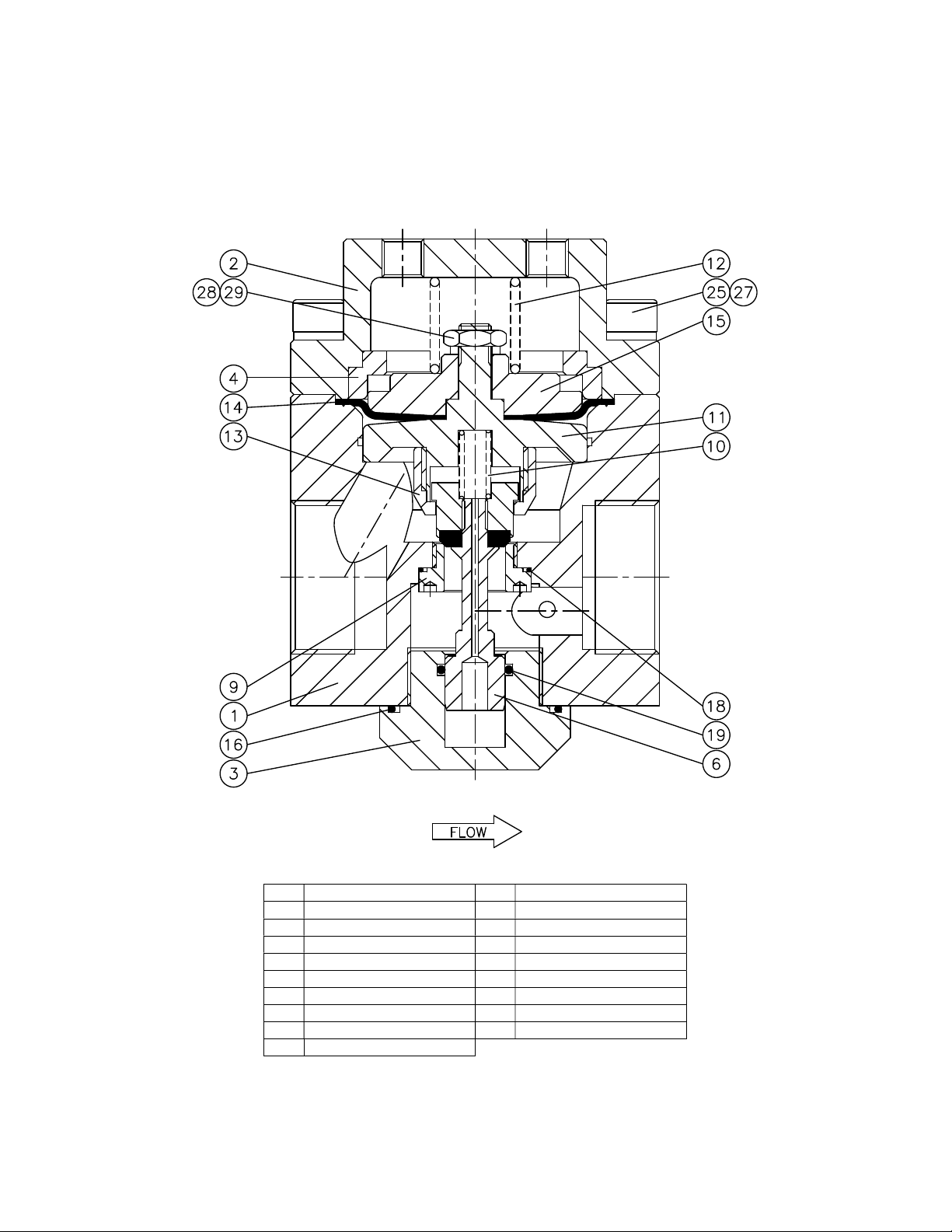
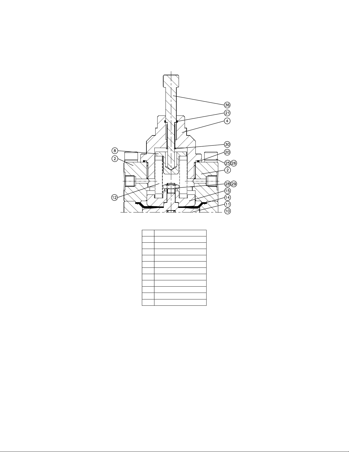
Disassembly
▪ Loosen the hexagon socket head screws and remove the dome, dome plate, diaphragm, body
plate, and valve assembly.
▪ Loosen the retaining screw to remove the valve assembly.
▪ Loosen the bolt or nut from the diaphragm- and dome plate to remove the diaphragm.
▪ Loosen the bodyplug and remove the body plug and seat.
Inspection of disassembled parts
▪ Check all parts for abnormal wear. Replace parts in case of doubt.
Points of attention before assembly
▪ All parts must be clean and undamaged before starting assembly.
▪ Swagelok recommends replacing all O-rings and the diaphragm before assembly.
▪ All threaded parts must be lubricated a little before assembly, this to avoid galling of threads.
▪ All O-rings need to be lubricated a little to improve the lifetime of the O-ring and the performance
of the regulator.

10
Assembly
Follow the instructions for disassembly in reverse order to assemble the regulator.
Test the regulator for proper operation.
Recommended torques
CAUTION
Only tighten the bolts or parts if the regulator is completely depressurized.
▪ Hexagon socket head screws M8 25 N·m (221 in.·lb)
▪ Hexagon socket head screws M10 40 N·m (354 in.·lb)
▪ Nut M10 40 N·m (354 in.·lb)
▪ Body plug 40 N·m (354 in.·lb)
▪ Dome screw (-DP only) 50 N·m (442 in.·lb)

11
Troubleshooting
Problem: The outlet pressure creeps up, without increasing the dome pressure.
Cause: A damaged valve and/or seat and/or body plug O-ring and/or seat O-ring.
Solution: Replace the valve and/or the seat and/or the O-ring.
Problem: Leakage around the body plug.
Cause: A damaged O-ring or insufficient torque on the body plug.
Solution: Replace the O-ring or tighten the body plug according to the torque specifications.
Problem: Leakage between the body and the dome.
Cause: A damaged diaphragm or insufficient torque on the bolts.
Solution: Replace the diaphragm or tighten the bolts according to the torque specifications.
Problem: The required set pressure can not be reached.
Cause: The inlet pressure is not high enough.
Solution: Make sure that the inlet pressure is sufficient.
Problem: The inlet pressure rises too much when going from a dynamic to a static situation.
Cause: There is too much flow in the dynamic situation.
Solution: A larger regulator is required.
Check the specific application data with the flow curves in our product literature, if available.
Problem: The inlet pressure does not drop if the pressure in the dome is lowered.
Cause: The valve assembly is sticking.
Solution: Replace the valve assembly.
Problem: The regulator will not relieve at the set point.
Cause: The valve assembly is sticking or the dome pressure is accidentally adjusted.
Solution: Replace the valve assembly or re-adjust the dome pressure.
Problem: The inlet pressure has changed without adjusting the dome pressure.
Cause: Changes to the outlet pressure will result in changes to the set pressure.
Solution: Maintain a constant outlet pressure on the regulator. See section “operation” about
dependency.

Warranty Information
Swagelok® products are backed by The Swagelok Limited Lifetime Warranty.
For a copy, visit swagelok.com or contact your authorized Swagelok representative.
For additional information, see www.swagelok.com.
Swagelok, Snoop—TM Swagelok Company
© 2011-2022 Swagelok Company
MS-CRD-0153, RevC, February 2022
WARNING
Do not mix/interchange Swagelok products or components not
governed by industrial design standards, including Swagelok tube
fitting end connections, with those of other manufacturers.
Other manuals for RHPS Series
18
This manual suits for next models
6
Table of contents
Other Swagelok Industrial Equipment manuals
Popular Industrial Equipment manuals by other brands

Unipart Dorman
Unipart Dorman CLS LITE Operation & maintenance manual

Dorner
Dorner 3200 Series Installation, maintenance & parts manual

Dungs
Dungs GasMultiBloc MB-D B01 instructions

Leakomatic
Leakomatic M4i user manual

DANA
DANA NoSPIN S140 quick start guide

TDI
TDI MCL488 Series Operation & programming manual