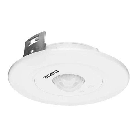
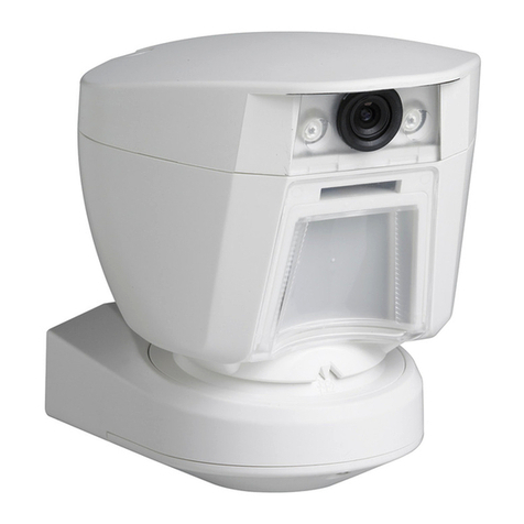
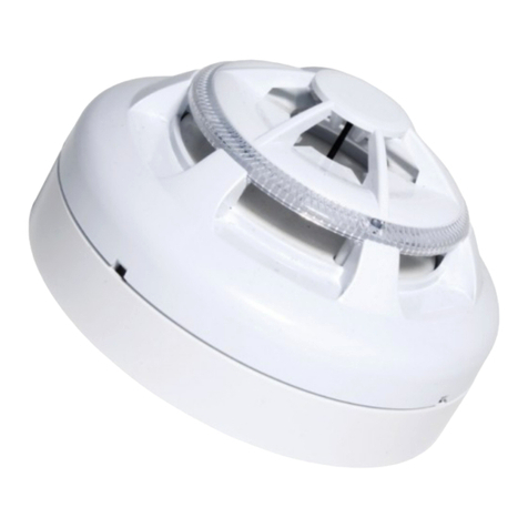
Essence Smartcare Care@Home ES700PIR User manual

Care@Home™
Passive Infrared Detector
User Guide
ESUGSC008
Version 1.0
September 2015

Legal Notice
Usage of this document, and all information (including product information) provided within, are subject to the following terms and conditions, and all
applicable laws. If you do not agree with these terms, please do not access or use the remainder of this document.
This document contains highly confidential information, which is proprietary to Essence SmartCare Ltd. and/or its affiliates (hereafter, "Essence"). No
part of this document's contents may be used, copied, disclosed or conveyed to any third party in any manner whatsoever without prior written
permission from Essence.
The information included in this document is intended for your knowledge and for negotiation purposes only. Essence makes no implicit representations
or warranties with respect to such information.
The information included in this document is subject to change without notice. Any decision to rely on the information contained herein shall be at your
sole responsibility, and Essence will not accept any liability for your decision to use any information or for any damages resulting therefrom.
Certain laws do not allow limitations on implied warranties or the exclusion or limitation of certain damages. If these laws apply to you, some or all of the
above disclaimers, exclusions, or limitations may not apply to you.
By using the information contained herein, you agree that the laws of the State of Israel, without regard to principles of conflict of laws, will govern any
dispute of any sort that might arise between you and Essence regarding the information contained herein, and any such dispute shall be settled
exclusively in the competent courts of Tel Aviv-Jaffa, Israel.
All registered or unregistered trademarks, product names, logos and other service marks mentioned within this document are the property of Essence, or
their respective owners. Nothing contained herein shall be construed as conferring by implication, estoppels, or otherwise any license or right, either
express or implied, under any patent or trademark of Essence or any third party. No use of any trademark may be made without the prior written
authorization of Essence.
This document and all of its contents are protected intellectual property of Essence. Any copying, reprinting, reuse, reproduction, adaptation,
distribution or translation without the prior written permission of Essence is prohibited.
Please check your End User License Agreement (EULA) for terms and conditions.
© 2015 All rights reserved to Essence SmartCare Ltd.
For more information, please contact: Essence SmartCare Ltd.
12 Abba Eban Avenue,
Ackerstein Towers Bldg. D
Herzliya Pituach, 4612001 Israel
www.essence-grp.com
Tel: +972-73-2447777
Fax: +972-9-7729962

Table of Contents
Care@Home™ Passive Infrared Detector User Guide 3
Table of Contents
1. Overview................................................................................................................................................ 4
2. Installation Preparation...........................................................................................................................5
2.1. Required Equipment .................................................................................................................. 5
2.2. Location Recommendations ...................................................................................................... 5
2.3. Best Practices ............................................................................................................................. 6
3. Installation ............................................................................................................................................. 8
3.1. Installing the PIR......................................................................................................................... 8
3.2. “Walk Test” Mode...................................................................................................................... 12
4. Installing Special Equipment..................................................................................................................13
4.1. Open and Close the PIR............................................................................................................. 13
4.1.1 Opening the PIR .......................................................................................................... 13
4.1.2 Closing the PIR............................................................................................................. 15
4.2. Pet Immune Lens.......................................................................................................................16
4.3. Optical Limiter ..........................................................................................................................18
5. Operation ............................................................................................................................................. 21
5.1. PIR Physical Attributes............................................................................................................... 21
5.2. Notifications.............................................................................................................................. 21
5.3. Supervision................................................................................................................................22
6. Maintenance......................................................................................................................................... 23
6.1. Replacing the Battery................................................................................................................23
7. Specifications........................................................................................................................................ 25
Installation Method Alternatives ............................................................................................ 27Appendix A
Using Mounting-Tape...........................................................................................................................27
Using Screws ........................................................................................................................................ 29
Required Equipment ................................................................................................................ 29
Installing the PIR with Screws ................................................................................................... 30
Terms, Abbreviations, and Acronyms......................................................................................31Appendix B
End User License Agreement and Terms & Conditions ..........................................................34Appendix C
Care@Home™ System Terms of Use ...................................................................................... 37Appendix D

Overview
4 Care@Home™ Passive Infrared Detector User Guide
1. Overview
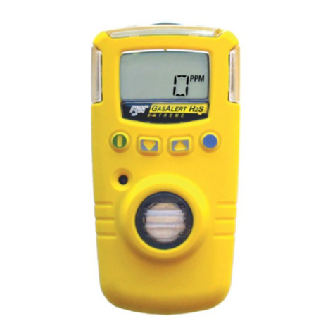
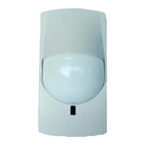
The Essence Passive Infrared Detector (PIR) is a battery operated, bi-directional, wireless motion
detector.
The PIR has the following features:
A maximum detection angle of 105° horizontal, 80° vertical
A maximum detection range of 12 m (40 ft.)
Detection algorithms including false alarm suppression
Sealed optics with insect immunity
Daylight immunity
White ESI 4th Generation DragonflyEye™Multi-Zone spherical lens
A mounting-base with mounting (double-sided adhesive) tape
Figure 1: Essence Passive Infrared Detector
The PIR peripheral device model identification number is ES700PIR.
NOTE: The images of batteries included in this User Guide are for illustration
purposes only.
Only batteries thoroughly tested and approved by Essence should be used to
meet the device’s specifications. A list of the approved batteries and their
specifications is provided in Table 3 on page 26.

Installation Preparation
Care@Home™ Passive Infrared Detector User Guide 5
2. Installation Preparation
The following are the steps and processes to prepare for the installation of the PIR.
2.1. Required Equipment
Before beginning, prepare the following equipment:
Double-sided adhesive mounting tape - provided.
One 3V CR123A Lithium battery that has a nominal battery life of 3 years
NOTE: To comply with the UL certification standards, use GP International Ltd.
batteries.
2.2. Location Recommendations
Consider the following when selecting a mounting location for the PIR:
A flat wall surface or a corner in a room
A surface that is clean, dry, and smooth
Within 700 m (2296 ft.) of the CP (open air nominal)
A coverage area within view of the PIR detection angle and range:
Maximum detection angle of 105° horizontal, 80° vertical
Maximum detection range of 12 m (40 ft.)
Installation height of 2 m-2.2 m (6.6-7.2 ft.)
Avoid installing on door frames.
Avoid tall, large objects, such as a bookcase or a cabinet, which even partially obscure the PIR’s
field of vision.
Avoid locations with moving objects in the coverage area, such as curtains or lighting fixtures
with hanging parts.
Avoid locations directly in front of an air conditioner or heat source.

Installation Preparation
6 Care@Home™ Passive Infrared Detector User Guide
A “Combined Bathroom” is a bathroom that includes a toilet. Because this type of bathroom
includes two types of activities, it is important to ensure that both activities are monitored
separately. If there is a “Combined Bathroom” on the premises, you must install special
equipment into the restroom PIR, to capture the restroom activities.
For instructions about the installation in a combined bathroom, see section 4.3 on page 18.
2.3. Best Practices
When installing the Pro or Family systems, the PIR should be installed in accordance with the following
guidelines:
Avoid overlapping coverage areas:
When coverage areas overlap and the resident is detected by both PIRs, each PIR sends a
detection event to the CP as if the Resident is in two places at one time. Overlapping coverage
can cause false detection reporting.
Separate coverage areas ensure distinct identification of the activity area for each PIR.
For example, Figure 2 below presents a typical apartment with a typical installation of five PIRs.
Figure 2: Motion Detectors Installation Example

Installation Preparation
Care@Home™ Passive Infrared Detector User Guide 7
Avoid installing a PIR directly opposite a door.
For example, when the Resident passes the open bathroom door through the hallway, if the
bathroom PIR is installed facing the door, the PIR sends a bathroom event to the CP reporting
that the Resident is entering the bathroom.
Installation recommendations per room:
Install the PIRs 1.5–2 m (5–6.6 ft.) or more above the floor, to allow for maximum
coverage.
Install the bedroom PIR opposite the bed to ensure the entire bed is covered.
Install the living room PIR diagonal to the couch and if possible, not opposite the dining
room.
Install the dining room PIR diagonal to the dining room table and if possible, not facing
the living room.
Install the lavatory PIR 30-50 cm (1–1.6 ft.) above the basin depending on the distance
from the basin.
Install the bathroom PIR diagonal to the sink and the bathtub and if possible, not opposite
the door.
Ensure there is no overlap of the PIR coverage areas when the dining room and living room are
combined. Install the two PIRs “back to back”, such that their locations enable separation of
the two types of activity events:
Living room activity
Dining room activity
Figure 3 below illustrate of a possible solution for installation when a living room is adjacent to
the dining room.
Figure 3: Combined Living Room and Dining Room

Installation
8 Care@Home™ Passive Infrared Detector User Guide
3. Installation
The floor plan of the Resident’s premises determines the installation of the PIR. The life style of the
Resident can require special equipment, such as:
Pet Immune lens
Optical Limiter
For information about the special equipment and installation instructions, see chapter 4 on page 13.
This chapter defines the:
Standard installation process
Testing the installation
3.1. Installing the PIR
To install the PIR, perform the following procedure:
1. Identify the location for mounting the PIR, according to the criteria in section 2.2 on page 5.
2. Clean the surface of the mounting location thoroughly. Make sure the location is dry.
3. Release the PIR mounting-base by lifting the tab and pushing it forward, as illustrated in Figure 4
below.
Figure 4: Release the Mounting-Base

Installation
Care@Home™ Passive Infrared Detector User Guide 9
NOTE: Refer to Appendix A,on page 29, for information about installing the PIR
using screws.
4. Install the mounting-base with mounting-tape:
Peel off the protective strips from the mounting-tape, required for the installation location.a.
Press the mounting-base into place.b.
5. If the PIR requires special equipment, install it now. For instructions on installing the special
equipment, see chapter 4 on page 13.
6. If the PIR is not from the Care@Home™kit, add the PIR to the Care@Home™system by “pairing” the
PIR with the CP.
Press the PAIRING button, located on the right edge of the front of the CP, for five seconds. The CP
beeps and the ring, around the EMERGENCY button, lights up in Blue with a circular movement.
7. Open the battery compartment cover by sliding it upwards, as illustrated in Figure 5 below.
Figure 5: Open Battery Compartment
8. Insert the battery, according to the compartment polarity, as illustrated in Figure 6 below. Use a 3V
CR123A Lithium battery.

Installation
10 Care@Home™ Passive Infrared Detector User Guide
Figure 6: Battery Insertion
When the battery is installed, the LED lights up Red, indicating that the PIR has powered up
successfully.
Figure 7: LED Indicator
WARNING! A new battery can explode if it is incorrectly installed. Discard used
batteries responsibly.
Remember: To comply with the UL certification standards, use GP International
Limited batteries.
9. Holding the PIR, move at least 2 m (~6 ft. 7 in.) from the CP.

Installation
Care@Home™ Passive Infrared Detector User Guide 11
10. If the PIR is not from the Care@Home™kit, ensure that the pairing process is successful. The
process can have the following results:
If the pairing process is successful, the CP beeps and the ring, around the CP EMERGENCY
button, blinks Blue three times.
If the pairing process is not successful, the CP beeps and the ring lights up Red for two
seconds.
If the peripheral device is already paired, the CP beeps and the ring lights up alternating
between Blue and Red.
If no additional peripheral devices can be integrated, as when the CP memory is full, the CP
beeps and the ring lights up Red.
The CP returns to its previous operation mode automatically following the pairing process.
11. If the PIR is from the Care@Home™kit and pre-configured with the CP, shake the PIR gently until
the LED lights up Red,to establish a communication channel between the PIR and the CP.
The Communication LED on the CP blinks Green to confirm that the communication channel is
established.
Figure 8 – Green Communication LED on the CP
12. Close the battery compartment cover.
13. Insert the PIR into the mounting-base until the PIR clicks into place. Ensure that the lens is pointing
downward, as illustrated in Figure 9 below.
Communication LED

Installation
12 Care@Home™ Passive Infrared Detector User Guide
Figure 9: PIR with Lens Pointing Downward
3.2. “Walk Test” Mode
A Walk Test is a function and signal verification check. The test is used to determine the detection
area of the PIR.
The Walk Test mode starts automatically after the PIR powers up, such as:
When a new battery is inserted
After adding and pairing a new PIR with the Care@Home™system
This mode lasts 10 minutes.
During the Walk Test, any motion detection is signaled by the LED on the PIR. The PIR sends a
notification of the motion detection event to the CP.

Installing Special Equipment
Care@Home™ Passive Infrared Detector User Guide 13
4. Installing Special Equipment
When installing the Pro or Family systems, there are situations that require special equipment so that
the activity events are recognized correctly by the analytics algorithm.
If the premises includes rooms that “combine activities”, such as a bathroom with a toilet, you can
install special equipment to prevent overlapping coverage areas.
If the Resident has a pet, it is important to differentiate between the movement of the Resident and
the movement of the pet. Special equipment can be installed to enable the PIR to ignore the pet’s
movements.
The following equipment installed in the PIR can solve these situations:
Pet Immune Lens
Optical Limiter
4.1. Open and Close the PIR
To install the special equipment, you must open the PIR back cover. The circuit board is attached to
the inner compartment of the PIR back cover.
Caution: When working within the inner compartment of the PIR, it is important
to be careful not to damage the circuit board and other parts of the PIR.
4.1.1 Opening the PIR
To open the PIR, perform the following procedure:
Caution: Perform this procedure with special care since the top part of the
front panel is made of very thin plastic covering which might break if too
much pressure is applied.
1. If the PIR is already installed on the premises, dismount the PIR from the mounting-base, as
illustrated in Figure 24 on page 23.

Installing Special Equipment
14 Care@Home™ Passive Infrared Detector User Guide
2. If there are screws in the back cover, unscrew the two screws above the battery compartment at
the top of the back cover, as shown in Figure 10 below.
Figure 10: Unscrew the Screws
3. Holding the back cover upright, insert a flat screwdriver between the lock tab of the front panel
and the top of the back cover, as shown in Figure 11 below, pushing downward on the inner latch
tab, to release the back cover from the front panel.
Figure 11: Back Cover Latch Tab under Front Panel Lock Tab
4. Detach the back cover from the front panel.
Figure 12 below shows the front panel and the back cover of the PIR.

Installing Special Equipment
Care@Home™ Passive Infrared Detector User Guide 15
Figure 12: PIR: The Tabs of the Front Panel and Back Cover
4.1.2 Closing the PIR
To close the PIR, perform the following procedure:
1. Insert the tabs, at the bottom end of the front panel, into the inner square slots, at the bottom end
of the back cover, as illustrated in Figure 13 below.
Figure 13: Align and Insert Tabs in Square Slots
2. Position the top of the back cover onto the top of the front cover, while aligning the latch tab
under the lock tab of the front panel, as shown in Figure 11 on page 14.
3. Holding the PIR with the back cover facing you and both thumbs on the holes for the screws, press
the back cover into the front panel until the latch tab clicks under the lock tab of the front panel.
Alternatively, using a flat screwdriver, press downward on the back cover latch-tab until the latch
tab clicks under the lock tab of the front panel.
4. Screw-in the two screws, if screws are required.
5. Insert the battery, as required.
Front Panel Lock Tab Back Cover Latch Tab

Installing Special Equipment
16 Care@Home™ Passive Infrared Detector User Guide
6. Return the PIR onto the mounting-base such that the lens is pointing downward.
4.2. Pet Immune Lens
Figure 14 below shows the pet immune lens. The purpose of the pet immune lens is to reduce false
detections by suppressing motion detections of small objects such as pets.
Figure 14: The Pet Immune Lens
Caution: It is not recommended to install the Pet Immune Lens in a PIR that
includes an Optical Limiter. The coverage area of the PIR may be further
reduced.
To install the pet immune lens in the PIR, perform the following procedure:
1. Open the PIR as instructed in section 4.1.1 on page 13.
2. Release the PIR outer lens with a flat screwdriver by releasing the three latch tabs, which hold the
lens into place, as shown in Figure 15 below. Release the tabs as follows:
Push the side latch tabs towards the center and downward to release the tabs.a.
Push the bottom, center latch tab downward to release the tab.b.

Installing Special Equipment
Care@Home™ Passive Infrared Detector User Guide 17
Figure 15: PIR Lens Latch Tabs
3. The outer lens should fall free of the PIR when the latch tabs are released.
If the outer lens is not released, insert a dull thin object through the oval opening and gently push
the outer lens and release it, as illustrated in Figure 16 below.
Figure 16: Back Cover Oval Opening
4. Insert the pet immune lens into the opening for the lens in the PIR front panel. The pet immune
lens fits inside the opening of the PIR, as illustrated in Figure 17 below.
Figure 17: Assembling the Pet Immune Lens

Installing Special Equipment
18 Care@Home™ Passive Infrared Detector User Guide
5. Insert the outer lens in the groove surrounding the opening for the lenses, placing the PIR outer
lens on top of the pet immune lens, as shown in Figure 18 below.
Insert the latch tabs at the bottom center and at the side of the outer lens into the latch tab
openings on the PIR opening for the lenses. Figure 18 below illustrates in detail where and how to
install the outer lens. The side and center latch tabs hold both lenses in place.
Figure 18: Lens Tabs for PIR Lens Insertion
6. Close the PIR according to the instructions in section 4.1.2 on page 15.
4.3. Optical Limiter
In a combined bathroom, the optical limiter ensures a separation of the two types of activity events:
Restroom activity
Bathroom activity
Figure 19 below shows the optical limiter. The purpose of the optical limiter is to reduce the coverage
area of the PIR. The optical limiter is installed between the PIR detection mechanism and the PIR
lens(es).
Figure 19: Optical Limiter
Latch tabs at both sides and
at the center of the PIR Lens
Groove for lens positioning
Latch tab openings
Insert latch tab in opening

Installing Special Equipment
Care@Home™ Passive Infrared Detector User Guide 19
Figure 20 below illustrates a possible solution for installation in a combined bathroom.
Figure 20: Combined Bathroom Installation
For a PIR with an optical limiter, the coverage area radius is 0.25 of the installation height.
Table 1 below lists examples of the coverage area for a PIR depending on its installation height.
Table 1: Coverage Area for PIR with Optical Limiter
Installation Height Coverage Area Radius
2.0 m 0.50 m
1.8 m 0.45 m
2.2 m 0.55 m
For installation in a combined bathroom, first install the optical limiter in the restroom PIR.
To install the optical limiter, perform the following procedure:
1. Open the restroom PIR as instructed in section 4.1.1 on page 13.
2. Slide the optical limiter into the flat-end slot at the top of the oval opening, as illustrated in Figure
21 below.
Figure 21: Insert Optical Limiter
PIR with Optical Limiter
PIR for standard coverage area

Installing Special Equipment
20 Care@Home™ Passive Infrared Detector User Guide
3. Depress the limiter until it completely fits into place, as shown in Figure 22 below. Otherwise, the
PIR cannot close properly.
Figure 22: Optical Limiter installed in PIR
4. Close the PIR according to the instructions in section 4.1.2 on page 15.
5. Install the restroom PIR over the toilet.
6. Install the bathroom PIR such that the PIR coverage area includes the entire bathroom.
Table of contents
Other Essence Smartcare Security Sensor manuals
