essential US 48V GC2 User manual

CONTENTS
1 BEFORE YOU START 4
1.1 SAFETY 4
1.2 EQUIPMENT NEEDED 4
1.3 SAFETY DATA SHEETS (MSDS) 5
2 BATTERY SPECIFICATIONS
OVERVIEW 6
3 BATTERY OPERATION 8
3.1 TURNING ON 8
3.2 TURNING OFF 8
3.3
ACTIVE MODE AND SOC DISPLAY 8
3.4 DISPLAY WHILE CHARGING 9
3.5 FAULT DISPLAY 9
3.5
FAULT TROUBLESHOOTING
10
4 INSTALLATION
11
4.1 CABLE SIZE AND BOLT/NUT
SPECIFICATION 11
4.2 TERMINAL PROTECTION AND
INSTALLATION 12
4.3 BATTERY ORIENTATION 12
4.4 PARALLEL BATTERY
CONNECTIONS 12
4.5 ACCESSORIES 13
4.6 BATTERY ENVIRONMENT 13
5 ELECTRICAL
SPECIFICATIONS 15
5.1
DISCHARGE SPECIFICATION 15
5.2
BMS PROTECTION CRITERIA 16
6 CHARGING 17
6.1 BEFORE CHARGING 17
6.2 CHARGING PROFILES 17
6.3 CELL BALANCING 19
6.4 CHARGING FAQS 19
7 CANBus 20
8 RECOMMENDED
BATTERY PACK SIZES
21
9 STORAGE 22
10 SHIPPING 22
10.1
REGULATORY INFORMATION
22
10.2 PACKAGING 23
11
ADDITIONAL INFORMATION
24
11.1 TERMINOLOGY 24
11.2 CHARGER
OPTIMIZATION/DIAGNOSIS 24
11.3 DISCHARGE TESTING 25
11.4 C-RATES 25
11.5 PRODUCT SPECIFICATION
SHEETS 26
11.6 DATE CODES 26
11.7 WARRANTY 26
11.8 BATTERY DEALERS NEAR YOU 26
12 BATTERY RECYCLING 27
13 NOTES 28

4U.S.Battery Mfg. Co.
1 BEFORE YOU START
The following Safety and Equipment sections are provided to ensure
safe and successful battery installation and maintenance.
1.1 SAFETY
Batteries can deliver an enormous amount of power that can result in injury and/or
death, observing the following precautions is the difference between successful battery
maintenance/installation and a night in the emergency room:
●Wear safety glasses and rubber gloves when working with batteries.
●Use insulated tools with rubber or plastic handles.
●Keep ignition sources and combustible material away from batteries.
●Remove all metal jewelry or other objects when working with batteries.
●Never place objects on top of batteries. A short circuit can occur.
●Make sure all electrical connections are tight (see 4.1) and free of damage
●Only use the built-in handles to move/install batteries.
●Review the Safety Data Sheet prior to handling/storage of batteries
WARNING! Do not disassemble, heat above 140˚F, or incinerate batteries!
Risk of re, explosion, and/or burns. ABC type re extinguishers should be
kept near batteries in case of re. Refer to SDS for more information.
WARNING! Replacing lead-acid batteries with lithium-ion batteries results
in a reduction in weight that can impact vehicle/machine dynamics.
Counterweights may be required to reduce rollover risk. Consult the
machine manufacturer or an installation professional.
1.2 EQUIPMENT NEEDED
The following equipment is recommended to safely maintain/install your batteries:
●Personal Protective Equipment
●Insulated Wrench
●Voltmeter
●Torque Wrench
●CAN bus Communication Cables
●Lithium-Ion Battery Compatible Charger
5
GC2 Lithium-ion User Manual
1.3 SAFETY DATA SHEETS (MSDS)
U.S. Battery has safety data sheets available for all product lines:
Lithium-Ion Safety Data Sheet

6U.S.Battery Mfg. Co.
2 BATTERY SPECIFICATIONS
OVERVIEW
US 48V GC2 US 24V GC2
Description Specications
Cell Conguration 16S1P 8S1P
Cell Type LFP Prismatic LFP Prismatic
Nominal Capacity* 30Ah 67Ah
Nominal Voltage of Pack 51.2V 25.6V
Rated Energy of Pack 1.5kWh 1.7kWh
Maximum Charge Voltage of Pack 58.4V 29.2V
Discharge Cutt-off Voltage of Pack 40V or 2.5V/cell 20V or 2.5V/cell
Recommended Charging Current 15A (C/2) 30A
Recommended Discharge Current 15A (C/2) 30A
Maximum Continuous Charging Current 30A* (1C) 67A* (1C)
Maximum Continuous Discharge Current 90A* (3C) 100A* (1.5C)
Operating
Temperature
Charge 0-55ºC / 32-131ºF 0-55ºC / 32-131ºF
Discharge -30-60ºC / -22-140ºF -30-60ºC / -22-140ºF
Operating Humidity <90%RH <90%RH
Storage Temperature 10-35ºC / 50-95ºF 10-35ºC / 50-95ºF
Storage Humidity 25-85%RH 25-85%RH
Enclosure Material ABS + PC ABS + PC
Dimensions LxWxH (mm) 10.24” (260) x 7.09”
(180) x 11.04” (280)
10.24” (260) x 7.09”
(180) x 11.04” (280)
Weight 14.6 kg / 32.2 lbs. 14.6 kg / 32.2 lbs.
Communication System CANBus CANBus
Ingress Protection Rating IP67 IP67
Safety Certications UL2580 (cell),
UL2271 (battery)
UL2580 (cell),
UL2271 (battery)
Shipping Classication UN38.3 Class 9 UN38.3 Class 9
Terminals Threaded Insert
(M8x1.25)
Threaded Insert
(M8x1.25)
TABLE 1
*REPEATED OPERATION AT OR NEAR MAXIMUM CONTINUOUS CHARGE OR DISCHARGE CURRENT WILL RESULT
IN HIGH TEMPERATURES AND REDUCED BATTERY LIFE

7
GC2 Lithium-ion User Manual
A
E
F
G
H
I
J
BCD
A. Negative Terminal (M8 insert)
B. Aluminum Heat Sink
C. Battery Status Indicator LEDs
(SOC)
D. Lift Handle
E. Button LED
F. Wake/Status Button
G. Positive Terminal (M8 insert)
H. In/Out CANbus Ports
I. Lift Handle
J. Pressure relief valve
DIAGRAM 1

8U.S.Battery Mfg. Co.
3 BATTERY OPERATION
The Essential Lithium-Ion GC2 batteries are
equiped with an integrated button and LEDs to
assist with turning battery on/off, SOC deter-
mination, fault/error handling, and status ref-
erence. Below is a description of the various
button and LED functions.
3.1 TURNING ON
To turn on battery, press and hold the button for 5 seconds. LEDs should light up indi-
cating the SOC of the battery. Voltage should be present at the terminals and the But-
ton LED should ash green every 5 seconds. Note that if multiple batteries are con-
nected in parallel, turn-ing on one battery will turn on all batteries in a string
3.2 TURNING OFF
To turn off, tap once and then tap and hold the button for at least 6 seconds. LEDs 2
and 4 should light up indicating you can release the button to power off. Voltage should
no longer be present at the terminals and the Button LED should no longer be ashing.
Note that if multiple batteries are connected in parallel, with CAN cables installed, turn-
ing off one battery will turn off all batteries.
3.3 ACTIVE MODE AND SOC DISPLAY
When the battery is on and there are no faults/errors, the battery is in “Active” mode.
This mode is identied by the green Button LED ashing every 5 seconds. In this
mode, the battery is ready to be used and voltage is present at the terminals. While in
this mode, you can tap the button once to reveal state of charge as indicated in
“Table 2”. Note that this will display for 5 seconds:
Button LED
DIAGRAM 2

9
GC2 Lithium-ion User Manual
SOC LED1 LED2 LED3 LED4 LED5
1%~9% Flash
10%~20% On
21%~45% On On
46%~70% On On On
71%~95% On On On On
96%~100% On On On On On
3.4 DISPLAY WHILE CHARGING
SOC LED1 LED2 LED3 LED4 LED5
1%~20% Pulse
21%~40% On Pulse
41%~60% On On Pulse
61%~80% On On On Pulse
81%~99% On On On On Pulse
100% All off, button LED is solid green
TABLE 2
TABLE 3
3.5 FAULT DISPLAY
When faults are active, the Button LED will ash red every 5 seconds. To determine the
specic fault(s) that is active tap the button once. The Button LED will stay solid red for
5 seconds and the LEDs will indicate the specic fault.
If multiple faults are active, tap the button to cycle through the faults. Once all faults
have been displayed, the SOC will be displayed, which is indicated by the Button LED
changing from red to green.

10 U.S.Battery Mfg. Co.
Fault LED1 LED2 LED3 LED4 LED5
Under Voltage On
Charge Over Current On
Discharge Over Current On On
Short Circuit On
Charge Over Temp. On On
Charge Under Temp. On On On
Discharge Over Temp. On
Discharge Under Temp. On On
TABLE 4
3.5 FAULT TROUBLESHOOTING
UNDER VOLTAGE
Battery has been overdischarged. The batteries need to be charged immediately. If
the batteries are in a motive application, wait approximately 15 minutes to allow the
voltage to increase. If the fault is no longer active, turn on the vehicle and drive imme-
diately to the charging station. Fully recharge the battery pack.
OVER CHARGE CURRENT
Charge current is greater than the maximum allowed. Verify charger is designed for
Lithium Ion and that the algorithm is also set for Lithium Ion.
OVER DISCHARGE CURRENT OVER DISCHARGE CURRENT
Discharge load is greater than the maximum allowed. Verify that the battery pack is
sufciently sized for the application. Installing an additional battery in parallel may be
required in order to decrease the discharge load across each battery below the maxi-
mum allowed.
SHORT CIRCUIT
Stop operation immediately. Short circuit protection is activated when when the dis-
charge current exceeds the short circuit limit in Table 6. This is a dangerous scenario
and should be handled with extreme caution. Verify that all connections are secure
and free of obstructions. Verify that batteries are clean of all debris. If fault occurs
again, have a professional evaluate the electrical system.

11
GC2 Lithium-ion User Manual
4.1 CABLE SIZE AND BOLT/NUT SPECIFICATION
Cable Size with Max Ampacity Table
Cable size has a direct inuence on the voltage drop across the system. The following
are guidelines. A trained professional should verify that your system is correctly sized
and installed. Cables must be sized according to the expected load using “Table 5”.
CHARGE OVER TEMP
Battery internal temperature has surpassed the maximum. The battery must be al-
lowed to cool. The wait time is dependent on the ambient temperature and battery
box design. Battery cables can come loose and cause a signicant rise in tempera-
ture. Check that all battery cables are secure. If multiple batteries are in parallel,
make sure that there is at least a 1 inch gap surrounding the battery.
CHARGE UNDER TEMP
Battery Internal temperature has surpassed the minimum. Battery temperature must
be allowed to increase before usage. Do not heat the battery using external devices
such as heat guns, ovens, etc. To prevent future “under Temp” errors store the
batteries or vehicle inside a temperature controlled environment.
DISCHARGE OVER TEMP
Battery internal temperature has surpassed the maximum. The battery must be al-
lowed to cool. The wait time is dependent on the ambient temperature and battery
box design. Battery cables can come loose and cause a signicant rise in tempera-
ture. Check that all battery cables are secure. If multiple batteries are in parallel,
make sure that there is at least a 1 inch gap surrounding the battery.
DISCHARGE UNDER TEMP
Battery Internal temperature has surpassed the minimum. Battery temperature must
be allowed to increase before usage. Do not heat the battery using external devices
such as heat guns, ovens, etc. To prevent future “under Temp” errors store the batter-
ies or vehicle inside a temperature controlled environment.
4 INSTALLATION

12 U.S.Battery Mfg. Co.
Table values are from NEC table 321.15(B)16
for copper cables rated at 167˚F (75˚C), op-
erating at an ambient temperature of no more
than 86˚F (30˚C). Lengths in excess of 6 feet
(1829mm) may require heavier gauge wire to
avoid unacceptable voltage drop. In series/
parallel banks, it is preferable for all series
cables to be the same length, and all parallel
cables to be the same length. Refer to the
national Electrical Code for correct wire sizing
which can be located at http://www.nfpa.org/.
4.2 TERMINAL PROTECTION AND INSTALLATION
During installation and handling, ensure that terminals are covered with supplied ter-
minal protectors and only remove when ready to attach cables. It is recommended that
cables be installed while the battery is turned off. See “3 Battery Operation” for instruc-
tions on turning batteries on/off.
4.3 BATTERY ORIENTATION
Lithium-Ion batteries can be oriented in any direction except upside down.
4.4 PARALLEL BATTERY CONNECTIONS
Lithium-Ion batteries should never be installed in series connection. Only parallel
connections are recommended. You can increase the capacity by creating a parallel
connection as shown in “Diagram 3”.
Never install multiple batteries in parallel without rst checking the SOC. The best way
to ensure batteries are matched is by fully charging each battery prior to installation in
parallel. Another way would be to ensure voltages are within 0.5V of one another prior
to installation. Always install the batteries in the “Off” state by following
“3 Battery Operation”.
Cable/Wire Gauge Size
(AWG)
Ampacity
(Amps)
14 20
12 25
10 40
8 65
6 95
4 125
2 170
1 195
1/0 230
2/0 265
4/0 360
TABLE 5
13
GC2 Lithium-ion User Manual
4.5 ACCESSORIES
Never connect accessories directly to the batteries (except for the U.S. Battery compat-
ible remote display). 12V accessories should use a DC-DC power converter that is tied
into the key switch of the vehicle. Accessories should be installed in a way that they do
not drain the batteries while not in use. Please consult your U.S. Battery dealer when
installing accessories on vehicles using lithium-ion batteries.
4.6 BATTERY ENVIRONMENT
• Ventilation
Lithium-Ion batteries do not need ventilation during charging. In rare and adverse
scenarios, a lithium-ion battery may vent momentarily to release pressure from a cell
release. If this occurs, please discontinue use (charging or discharging) of the battery
and contact U.S. Battery technical support.
When using multiple batteries in parallel, it is extremely
important that batteries are at the same state of charge (SOC)
when installed.
PARALLEL CONNECTION
To increase capacity without
increasing voltage
Two US 48VGC2, rated at
30AH each connected in
parallel
Nominal System Voltage:
51.2V
System Capacity: 60AH
Example
DIAGRAM 3
14 U.S.Battery Mfg. Co.
• Environment
Batteries should always be installed or stored in a clean, cool, and dry place. Keep
water, oil, and dirt away from the batteries. If these materials are allowed to accumu-
late on the batteries, current leakage can occur resulting in self-discharge and possible
short-circuits. For the same reason, relative humidity should be kept below 90%.
• Temperature
The recommended operating temperature range for US Battery lithium-ion batteries is
listed in “Table 1” on page 6. Temperature plays a major role in battery usage. Hot
batteries will deliver more capacity, but with diminished cycle life. Cold batteries deliver
less capacity and are harder to charge. Temperature variations between cells can also
have a negative effect on battery capacity and life. Temperature impact on performance
is demonstrated below:
Temp.= 50˚C
Temp.= 25˚C
Temp.= -5˚C
Performance of Lithium Battery Pack @0.5C Discharge
Capacity (%)
0%
43.0
44.0
45.0
46.0
47.0
48.0
49.0
50.0
51.0
52.0
53.0
54.0
55.0
10% 20% 30% 40% 50% 60% 70% 80% 90% 100% 110%
CHART 1

15
GC2 Lithium-ion User Manual
5.1 DISCHARGE SPECIFICATION
Lithium-Ion batteries have a relatively “at” discharge curve when compared to lead-ac-
id batteries. In other words, the voltage stays level for most of the discharge until the
very end. Therefore, estimating the state of charge (SOC) using voltage is unreliable.
Many electric vehicles designed for lead-acid batteries have SOC displays that rely
on voltage and as such these displays will no longer be accurate when used with lithi-
um-ion batteries. The only way to determine SOC is by viewing the LEDs on the
battery or with the U.S. Battery Remote SOC Display.
1.0C Discharge
0.5C Discharge
0.2C Discharge
Performance of Lithium Battery Pack @25˚C
Capacity (%)
0%
40.0
41.0
42.0
43.0
44.0
45.0
46.0
47.0
48.0
49.0
50.0
51.0
52.0
53.0
54.0
55.0
10% 20% 30% 40% 50% 60% 70% 80% 90% 100% 110%
5 ELECTRICAL
SPECIFICATIONS
CHART 2

16 U.S.Battery Mfg. Co.
5.2 BMS PROTECTION CRITERIA
The battery management system is designed to disconnect the battery cells from the
terminals to protect the battery from damage in adverse conditions. Note that
this may cause vehicles to lose power, resulting in loss of control. Do not operate
batteries outside of the specications listed below. Below is a list of the conditions
under which the BMS will disconnect:
Charge Over Voltage Protection (Cell) 3.65 V
Charge Over Voltage Protection Release (Cell) 3.40 V
Charge Over Voltage Protection (Pack) 57.6 V
Discharge Over Voltage Protection (Cell) 2.50 V
Discharge Over Voltage Protection Release (Cell) 2.90 V
Charging Over Current Protection 35A for 5 Sec
Discharge Over Current Protection 1 105A for 30 Sec
Discharge Over Current Protection 2 150A for 20 Sec
Discharge Over Current Protection 3 175A for 10 Sec
Discharge Over Current Protection 4 200A for 5 Sec
Discharge Over Current Protection 5 440A for 0.03 Sec
Short Circuit Current Protection 560A ~Instant
Charge Over Temp >131ºF(55ºC)
(Release:122ºF(50ºC))
Charge Under Temp <32ºF(0ºC)
(Release:31ºF(5ºC))
Discharge Over Temp >140ºF(60ºC)
(Release: 131ºF(55ºC))
Discharge Under Temp <-24ºF(-30ºC)
(Release: -13ºF(-25ºC))
Overcurrent Release Time (Charging) 30 Sec
Over Current Protection 1-4 Release Time
(Discharging)
30 Sec
Over Current Protection 5 and Short Circuit \Release Time
(Discharging)
30 Sec
*4 consecutive conditions
will lock battery and require
button press to release
TABLE 6

17
GC2 Lithium-ion User Manual
6 CHARGING
6.1 BEFORE CHARGING
Proper charging is critical to maximize battery performance and life. Both under- and
over-charging batteries can signicantly reduce the life of the battery and cause a safe-
ty hazard. For proper charging, refer to the instructions that came with your equipment.
Most chargers are automatic and pre-programmed. Some chargers allow the user to
set the voltage and current values.
6.2 CHARGING PROFILES
When charging lithium-ion batteries, it is important to select the correct charge pro-
le/setting to ensure safety and performance. Using incorrect charging proles or
methodologies can reduce performance and life and may result in battery fault
conditions. When in doubt, contact U.S. Battery.
Lithium-ion batteries most commonly are charged using a two-stage prole often called
IU or CC-CV proles. The two stages consist of a constant current (CC) charge step
(charge current is xed while voltage rises) followed by constant voltage (CV) charge
step (voltage is held constant while current falls).
Below are the charging setpoints compatible with the 24 volt and 48 volt lithium
batteries:
-Max Output Current (CC) of 0.5C of pack capacity in Amps
o For example, a 60Ah pack has a recommended current
is 30 Amps or less
-Max Voltage (CV) at 3.45 - 3.55 volts per cell
o For example, a 48V application (16 cells) should be
charged at 55.2 - 56.8 Volts. For 24V application (8
cells), voltage range of 27.6 - 28.4 Volts
18 U.S.Battery Mfg. Co.
Below is a generic lithium iron phosphate cell charging curve:
U.S. Battery has worked with major charger manufacturers to develop more advanced
charging proles to enhance performance and life of the batteries. When possible, se-
lect the U.S. Battery lithium-ion charge proles available from the charger manufactur-
er. The following is an example of these proles:
CHART 3
V - 100%DOD
V - 35%DOD
3.80
3.70
3.60
3.50
3.40
3.30
3.20
3.10
3.00
5% 15% 25% 35% 45% 55% 65% 75% 85% 95% 105%
State of Charge (%)
Charging Characteristics of Lithium Battery Pack
U.S. Battery’s Recommended Charge Profile (multi-stage)
CHART 4
0 25
Voltage Current
50 75 100
0
0.1
0.2
0.3
0.4
0.5
0.6
2.2
2
2.4
2.6
2.8
3
3.2
3.4
3.6
3.8
4
State of Charge (%)

19
GC2 Lithium-ion User Manual
6.3 CELL BALANCING
Lithium-Ion battery packs contain multiple cells in series and/or parallel arrangements.
Due to inherent variations in cell manufacturing processes, no two cells are identical.
As a result, during charging and discharging, cells become “unbalanced” meaning they
are not at equivalent states of charge. If not properly managed, this can cause prema-
ture failure of the battery pack. To address this the battery management system (BMS)
“balances” cells by discharging the cells that are at a higher state of charge. This
brings these cells in closer alignment with other cells in the pack.
For this to occur properly, it is very important proper charging procedures are followed.
Cell balancing occurs at the end of charge and as a result this is the most critical
charging period.
6.4 CHARGING FAQS
The following is a list of common questions and concerns regarding system setup,
battery charging procedures. Please refer to these as general guidelines. For further
assistance with your specic system setup, please contact your Installer.
CAN I USE MY EXISTING LEAD-ACID CHARGER?
• This answer depends on the specic charger as some chargers contain multiple
settings. If the charger can be re-programmed or the settings can be changed
to accommodate “lithium iron phosphate” cells, then yes. However, lead-acid
charging proles or settings are not compatible. Contact the charger manufacturer
or authorized U.S. Battery distributor for information on how to determine if your
charger can be re-programmed.
HOW LONG DOES A CHARGE CYCLE TAKE?
• There are several factors that impact charge time: charger output power (wattage),
number of parallel batteries in pack, and state of charge of pack when charging
starts. But as a general idea, a 20A charger can charge a 48V 60Ah battery pack-
from 0 to 100% in about 3.5 hours.
20 U.S.Battery Mfg. Co.
CAN I OPPORTUNITY CHARGE?
• Yes, this is a great feature of lithium-ion batteries. They can be charged during a
break in usage and can quickly regain capacity. A good example would be plug-
ging in for an hour while on lunch to get extra runtime. While this does not harm
the batteries, it is important that full charge cycles are completed periodically for
cell balancing as mentioned in “6.3 Cell Balancing”.
DO THE BATTERIES GAS OR NEED VENTILATION?
• Lithium-ion batteries under normal operating conditions do not “gas”. The only ven-
tilation required would be for cooling the batteries if charging in high temperature
climates.
WHAT TEMPERATURES CAN I SAFELY CHARGE AT?
• The charging temperature range of the cells is 0-55ºC (32 -131ºF)
CAN YOU “EQUALIZE” LITHIUM-ION BATTERIES?
• No, equalization charging is specic to lead-acid batteries and may result in battery
fault conditions.
DIAGRAM 4
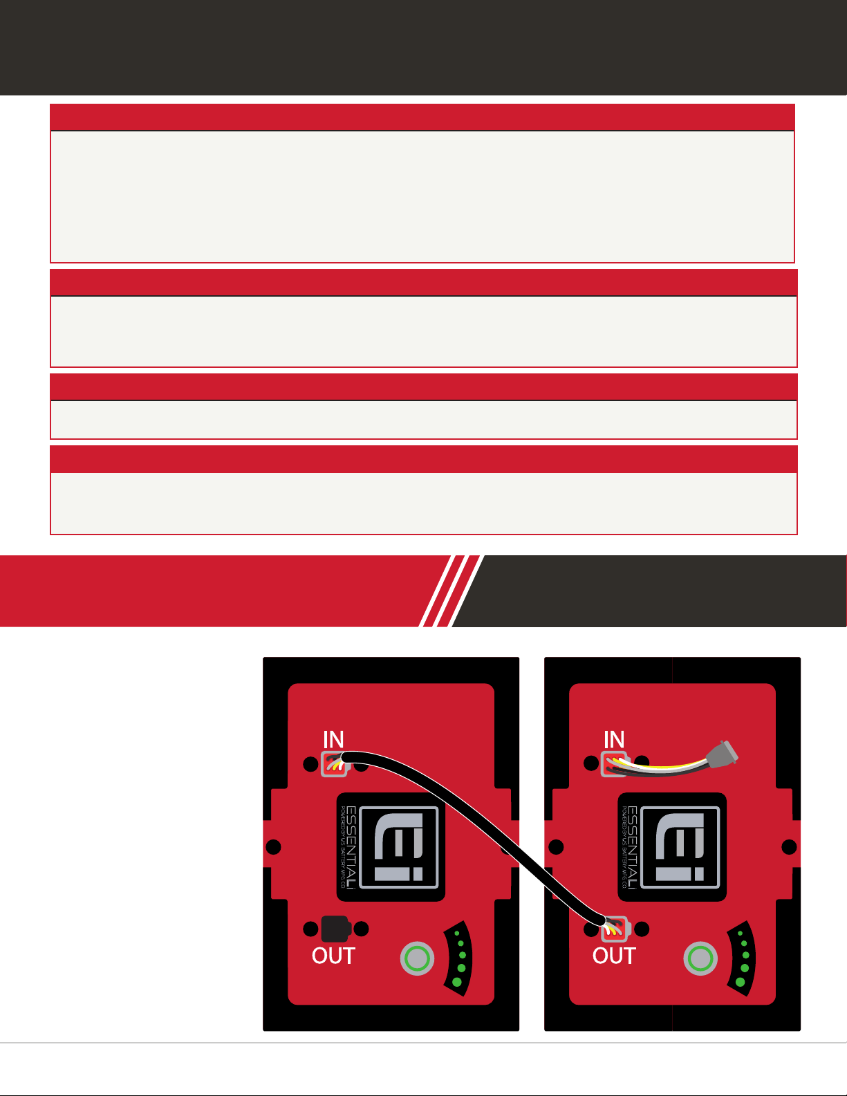
7 CANBus
CAN (Controller Area
Network) is a commu-
nication interface that
allows multiple batter-
ies and related compo-
nents (chargers, motor
controllers, remote dis-
plays, etc.) to commu-
nicate on a single bus.
Batteries communicate
details like state of
charge, battery faults,
voltage, etc. Each GC2
battery is supplied with
a CAN jumper cable
that should be installed

21
GC2 Lithium-ion User Manual
RECOMMENDED BATTERY PACK SIZES
Vehicle Usage Frequency
Normal High
Typical Golf Car Two 48V batteries,
60Ah
Three 48V
batteries, 90Ah
High Performance Golf Car
or Low Speed Vehicle (LSV)
Three 48V batteries,
90Ah
Four 48V batteries,
120Ah
Utility, Heavy Duty, or
Offroad Vehicles
Four 48V batteries,
120Ah
Five 48V batteries,
150Ah
between parallel batteries to allow for communication. This jumper should connect
from the “OUT” CAN port of one battery to the “IN” CAN port of the next battery. The
last battery in the string should also use a CAN termination plug in the nal “OUT”
CAN port for applications not using a remote display. See “Diagram 4”. For more de-
tailed CAN information please contact U.S. Battery technical support.
Below are recommended GC2 pack sizes for 48-volt standard golf cars, LSVs, utility
vehicles, and heavy-duty small electric vehicles. These recommendations are based
on generalized vehicle applications and serve only as a rough guide for users. Vehi-
cles with upgraded motor controllers, multiple passengers, heavy payloads, towing
setups, or any customization that would impact power requirements should consult
their U.S. Battery distributor for pack sizing.
8 RECOMMENDED
BATTERY PACK SIZES
TABLE 7

22 U.S.Battery Mfg. Co.
For long term storage (more than a month) batteries should be stored, fully charged,
and turned off. You can turn the batteries off by following the directions in “3 Battery
operation”. This will ensure low self-discharge rate and allow storage of up to one year.
Batteries will automatically enter a “sleep” mode after 72 hours of inactivity. Once sleep
mode is entered, a button press is required to “wake” the batteries. This can be done
on the U.S. Battery Remote SOC Display.
Beware of and isolate any electronics that may consume power even with the key
switch off such as DC-DC converters, stereos, lights etc.
9 STORAGE
10 SHIPPING
When shipping lithium-ion batteries, it is important to comply with all applicable inter-
national, federal, state, and local laws. The following information is a basic overview.
Below is a link to the U.S. Department of Transportation website for more in-depth
information on transporting lithium batteries:
https://www.phmsa.dot.gov/lithiumbatteries
10.1 REGULATORY INFORMATION
• UN ID Number: UN3480
• Proper Shipping Name: “Lithium ion batteries“
• Hazard Class Label: Class 9 Miscellaneous
• Air shipments require “Cargo Aircraft Only” label (§ 172.448) *
• DOT Hazmat Employee Training – All employees involved in the shipment, including
preparation for shipment are subject to the hazmat employee training requirements
of § 172.704.
• Hazardous Materials Shipping Paper – Shippers must prepare and offer a hazard-
ous materials shipping paper prepared in accordance with subpart C of part 172 of
the HMR (§§ 172.200-205).
• Emergency Response Information and Emergency Response Telephone Num-
ber – Shippers must provide the appropriate emergency response information and
emergency response telephone number per subpart G of part 172 of the HMR (§§
172.600-606).
This manual suits for next models
1
Table of contents
Popular Batteries Pack manuals by other brands

GreenWorks
GreenWorks 29652/BAF735 Operator's manual

Hoppecke
Hoppecke sun powerpack classic5.5/24 Installation and operating manual

Segway
Segway p Series Replacement instructions

Segway
Segway CUBE-BTX-1000 user manual

Mizco International
Mizco International ToughTested SOLAR 20 user manual

Conceptronic
Conceptronic CPOWERBK4400 quick guide


