genz III Series User manual

Product Manual
Lithium Ferro Phosphate (LFP) Battery Module
48V 2kWh and 3kWh 2RU Scalable Energy Solutions
Model Numbers GC48V-040LFP-2RU and GC48V-060LFP-2RU Series III
with or without rack tray kit

LFP Battery Module –Product Manual
All rights reserved genZ 2020
Issued for Use
Revision
Page
4/03/2020
2.1
2 of 25
1INTRODUCTION .................................................................................................................................................... 3
2GENERAL INFORMATION ...................................................................................................................................... 3
2.1 LIFE SUPPORT POLICY....................................................................................................................................................3
2.2 GENZENERGY PTY LTD ..................................................................................................................................................3
3SAFETY GUIDELINES.............................................................................................................................................. 4
4SPECIFICATIONS.................................................................................................................................................... 5
5MODULE OVERVIEW............................................................................................................................................. 5
5.1 BATTERY MANAGEMENT SYSTEM (BMS)..........................................................................................................................6
5.2 POWER IN/OUT J1 .......................................................................................................................................................6
5.3 EARTH POINT ..............................................................................................................................................................6
5.4 DUAL POLE 60AMP CIRCUIT BREAKER..............................................................................................................................6
5.5 FRONT PANEL KNURLED KNOBS ......................................................................................................................................6
6INSTALLATION ...................................................................................................................................................... 7
6.1 RECEIVING INFORMATION ..............................................................................................................................................7
6.2 INSTALLATION PLACEMENT.............................................................................................................................................7
6.3 INSTALLATION OF BATTERY MODULE(S) ............................................................................................................................7
6.4 CHARGER....................................................................................................................................................................7
6.5 INSTALLATION OF A SINGLE BATTERY MODULE ...................................................................................................................8
6.6 PARALLEL CONNECTION .................................................................................................................................................8
6.7 SERIES CONNECTION .....................................................................................................................................................8
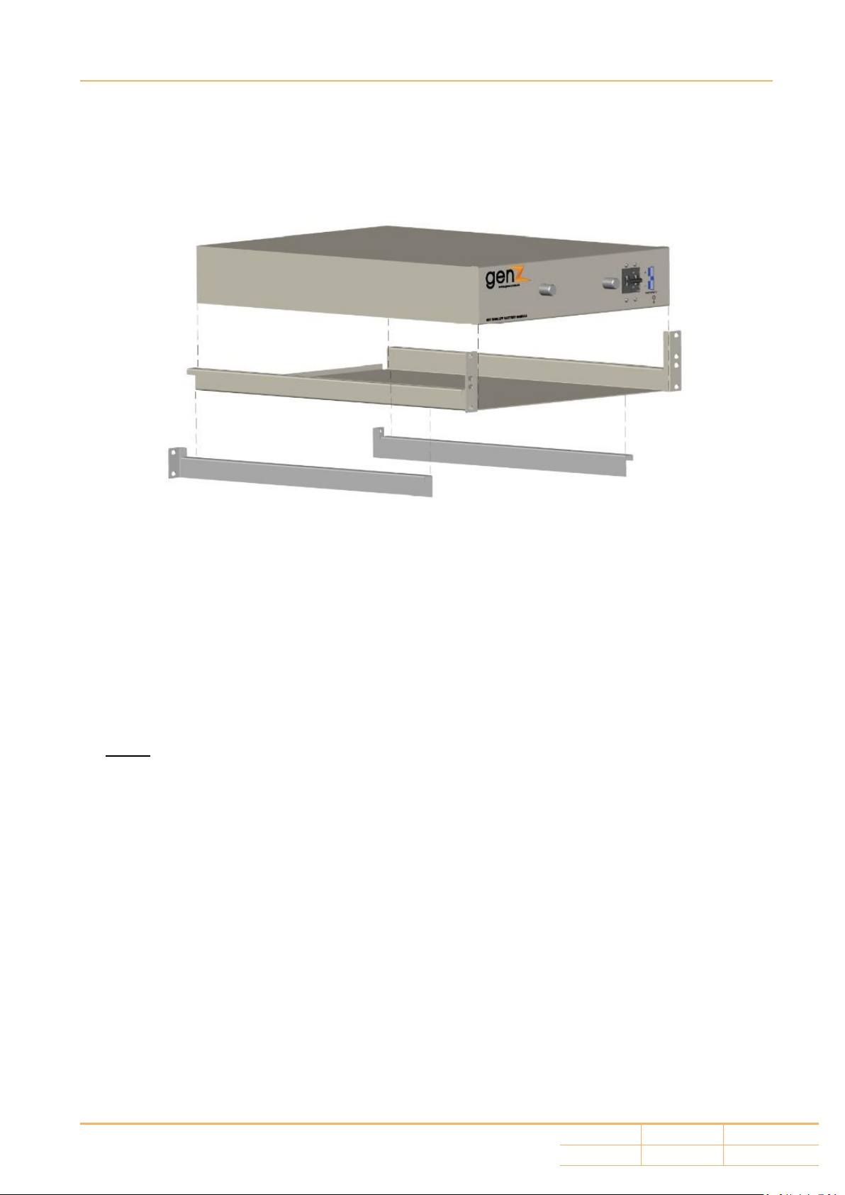
6.8 RACKMOUNT CONFIGURATION........................................................................................................................................9
6.9 CONNECTING THE BATTERY MODULE ...............................................................................................................................9
7OPERATION ........................................................................................................................................................ 10
7.1 TO TURN THE BATTERY MODULE ON AND OFF ...............................................................................................................10
7.2 POWER IN/OUT J1......................................................................................................................................................10
7.3 CHARGING THE BATTERY MODULE.................................................................................................................................10
7.4 DISCHARGING THE BATTERY MODULE ............................................................................................................................11
7.5 STORAGE ..................................................................................................................................................................11
8MAINTENANCE ................................................................................................................................................... 12
8.1 MONTHLY INSPECTION (SUGGESTED,NOT MANDATORY) ....................................................................................................12
8.2 ANNUAL INSPECTION (SUGGESTED,NOT MANDATORY) ......................................................................................................12
9WARRANTY & SERVICE INFORMATION............................................................................................................... 15
9.1 GENERAL INFORMATION ..............................................................................................................................................15
9.2 REGISTRATION ...........................................................................................................................................................15
9.3 BEFORE CALLING FOR SERVICE ......................................................................................................................................15
9.4 WARRANTY OR SERVICE...............................................................................................................................................16
10 APPENDIX A –DISCHARGE AND CAPACITY CURVES (25°C).................................................................................. 17
11 APPENDIX B –CIRCUIT BREAKER TRIP CURVE (BS) .............................................................................................. 18
12 APPENDIX C –DIMENSIONS................................................................................................................................ 19
12.1 2KWH MODULE AND TRAY .....................................................................................................................................19
12.2 3KWH MODULE AND TRAY .....................................................................................................................................21
13 APPENDIX D –WARRANTED OPERATING PARAMETERS ..................................................................................... 23

LFP Battery Module –Product Manual
All rights reserved genZ 2020
Issued for Use
Revision
Page
4/03/2020
2.1
3 of 25
1Introduction
Thank you for purchasing this LFP Battery Module. It has been designed and manufactured to provide
many years of trouble free service.
Please read this manual prior to installing any of the LFP Battery Module models. This product manual
covers the following battery module models:
GC48V-040LFP-2RU (48Volt, 2kWh, 40Ah, 2 Rack Unit high) Series III
GC48V-060LFP-2RU (48Volt, 3kWh, 60Ah, 2 Rack Unit high) Series III
This manual provides important information that must be followed during installation, commissioning
and maintenance of the Battery Modules. Failure to follow these instructions may lead to you
damaging the system it is being installed into and/or voiding your warranty. There are important
safety and handling procedures that must be followed for your own safety and the safety of those
around you.
This manual also contains information for customer support and factory service if it is required.
2General Information
2.1 Life Support Policy
We do not recommend the use of any of our products in ‘life support’applications where failure or
malfunction of the product can be reasonably expected to cause failure of the life support device or
to significantly affect its safety or effectiveness.
2.2 genZ Energy Pty Ltd
All Rights Reserved. All rights of this User Manual (“Manual”), including but not limited to the content,
information, and figures are solely owned and reserved by genZ Energy PTY LTD. (“genZ Energy”).
The Manual can only be applied to the operation or the use of this product. Any disposition,
duplication, dissemination, reproduction, modification, translation, extraction, or usage of this
manual in whole or in part is prohibited without the prior written permission of genZ Energy. Given
that genZ Energy will continuously improve and develop the product, changes may be made to the
information in this Manual at any time without obligation to notify any person of such revision or
change. genZ Energy will make all possible efforts to secure the accuracy and the integrity of this
manual. genZ Energy disclaims any kind or forms of warranty, guarantee, or undertaking, either
expressly or implicitly, including but not limited to the completeness, faultlessness, merchantability
or fitness for a particular purpose of the manual.

LFP Battery Module –Product Manual
All rights reserved genZ 2020
Issued for Use
Revision
Page
4/03/2020
2.1
4 of 25
3Safety Guidelines
Weight
These Battery Modules are heavy. Any time the Battery Module has to be handled be sure to use,
enough personnel, strong supports and suitable lifting equipment.
Risk of Electric Shock
Hazardous voltages maybe present on parts inside this module. Do not attempt to open or
disassemble the module. These Battery Modules contain no user serviceable parts.
Stored Energy
These Battery Modules can, especially if they are connected in parallel, produce high currents.
Qualified Service Personnel Only
Repairs and Battery replacement must be performed by qualified service personnel only.
Safety Data Sheet (SDS)
Refer to the SDS that was supplied with this module in case of an accident.

LFP Battery Module –Product Manual
All rights reserved genZ 2020
Issued for Use
Revision
Page
4/03/2020
2.1
5 of 25
4Specifications
NOTE: All Specifications shown are for an ambient temperature of 25C (77F) and
charge / discharge rates of 0.5C unless otherwise stated.
Model
GC48V-040LFP-2RU
Series III
GC48V-060LFP-2RU
Series III
Nominal Voltage
Direct Current (DC) 51.2V (48V)
Nominal Capacity
38.4Ah/2kWh
57.6Ah/3kWh
Nominal Current
19.2 Amps
28.8 Amps
Maximum Current
60 Amps (limited by circuit breaker)
Maximum DC Power
1966 Watts
2949 Watts
Minimum Charge Current
0.38 Amps
0.58 Amps
Maximum Charge Current
19.2 Amps
28.8 Amps
Charge/Discharge cycles to specified
Depth of Discharge (DoD)
Capacity retention >80%
10,000 @ 80% DoD
5000 @ 90% DoD
(2500@100% DoD and 1C)
Operating Temperature Limits
Charge 0° to 55°C
Discharge -20° to 60°C
Operating Humidity (non-condensing)
85%
IP Rating
IP50
Battery Case Dimensions (mm)
450D x 420W x 88H
570D x 420W x 88H
Battery Tray Dimensions (mm)
450D x 483W
570D x 483W
Tray Slide Range (mm)
480 to 760
590 to 880
Terminal Connection
Genuine Anderson SB50 BLUE
Weight Module
23.7kg
35kg
Weight Tray
Approximately 4.2kg
1 BMS Over Volt cut off
Approximately 58.4V
BMS Under Volt cut off
40V
BMS Short Circuit cut off
200 ± 30A (20mS Trip)
BMS Over Temp cut off
65°C
Charge time Approx.
2 hours at 19.2 A
2 hours at 28.8 A
Self-Discharge
14% per annum
Round Trip charge/discharge efficiency
>= 96%
Circuit Breaker Compliance
Double Pole, non-polarised, 60A IEC 60947-2
UN Type Number (Module chemistry)
UN 3480
Lithium Composition
As Lithium Ferro Phosphate, LiFePO4or LFP
Decisive Voltage Classification (DVC)
Class A
Casing /Coating
Steel / Satin white industrial coating
Certifications
See genz.com.au for details
1 The over voltage cut-out may vary from that stated. This is due to the fact that the BMS
protects the internal cell string voltages ahead of overall pack voltage.

LFP Battery Module –Product Manual
All rights reserved genZ 2020
Issued for Use
Revision
Page
4/03/2020
2.1
6 of 25
5Module Overview
5.1 Battery Management System (BMS)
This battery module is fitted (contained inside the battery module case) with a sophisticated BMS. The
BMS is designed to provide user safety and protect the battery cells from:
Over voltage charging.
Under voltage discharging.
Operation above a maximum temperature.
Short circuit protection. This is in addition to the protection provided by the circuit breaker.
Should the BMS activate to protect the module, the BMS will automatically reset once a normal
operational condition is detected by the BMS.
5.2 Power In/Out J1
The “POWER IN/OUT J1” connector is a standard Anderson SB50 (Blue) connector. The upper pin is
positive and the lower pin is negative.
5.3 Earth Point
Connects the chassis of the battery module to ground. Another earth stud is located at the rear
of the battery module.
NOTE: Neither the positive or negative terminal of this module is connected to the earth point. DC
from the battery module is floating.
5.4 Dual Pole 60Amp Circuit Breaker
This is the ON/OFF control for the battery module. Turning the “BATTERY CIRCUIT BREAKER” ON (up
is ON) will energise the “POWER IN/OUT J1” connector. It will also activate the power “ON” indicating
Light Emitting Diode (LED).
The “BATTERY CIRCUIT BREAKER” will trip in the event of a DC overcurrent condition.
NOTE: Before installing, ensure that the circuit breaker is in the down “OFF” position.
5.5 Front Panel Knurled Knobs
Knurled knobs are provided to assist in withdrawing the battery module from the battery shelf.

LFP Battery Module –Product Manual
All rights reserved genZ 2020
Issued for Use
Revision
Page
4/03/2020
2.1
7 of 25
6Installation
Failure to follow these guidelines will void the limited warranty and cause potential
damage to property or serious injury.
6.1 Receiving Information
Once you receive the product it should be visually inspected for damage that may have occurred
during shipping. Immediately notify the carrier and place of purchase if any damage is observed. The
packing materials that the product was shipped with has been designed to minimize any shipping
damage. In the unlikely event that the product needs to be returned to the manufacturer, use the
original packing material. Since the manufacturer is not responsible for shipping damage incurred
when the product is returned, the original packing material is inexpensive insurance.
6.2 Installation Placement
The Battery Module must be installed such that it is not exposed to:
Sources of heat or where the ambient temperature is expected to regularly exceed 55°C.
Extreme cold where the ambient temperature is expected to regularly fall below -10°C.
Direct sunlight.
Rain, water, salt laden air or where the humidity is likely to cause condensation.
A corrosive atmosphere.
Select a location, which will provide good air circulation for the Battery Module at all times. Route
cables so they cannot be walked on or damaged.
Refer to the specifications for specific operating parameters.
6.3 Installation of Battery Module(s)
Be sure to read the installation placement and associated cautions before installing the Battery
Module. Place the Battery Module in the final desired location and complete the rest of the
installation procedure.
These battery modules can be used in any orientation provided consideration is given to protecting
the circuit breaker, connector and indicator lamp from damage.
6.4 Charger
A charger specifically designed for charging LFP’s must be used or the use of a charger that has
configurable/programmable charging characteristics such that it meets the required profiles as
detailed in this manual. If in doubt, please contact the provider of this battery module or contact genZ
technical department for further guidance.

LFP Battery Module –Product Manual
All rights reserved genZ 2020
Issued for Use
Revision
Page
4/03/2020
2.1
8 of 25
6.5 Installation of a single Battery Module
Ensure that the following is considered prior to installing:
Use only genuine Anderson SB50 connectors.
Use the matching colour of Anderson SB50 connector as these connectors are keyed and (for
Example) only a blue Anderson will connect with a blue Anderson.
That the polarity of the connector is observed. + and –symbols are clearly marked on both
the connectors and the front panel of the module.
The correct size of cable to the battery connector is used.
6.6 Parallel Connection
In addition to the guidelines for a single module, when connecting in parallel, the following additional
considerations apply:
As the connection of these modules in parallel can result in high currents and stored energy,
the design of such a system should be made by a suitably qualified engineer.
All battery modules should be charged prior to installation as the modules may have
different states/levels of charge. Refer to the “Operation” section of this manual for
charging guidelines.
Do NOT install a fully discharged battery module into a fully charged bank of batteries.
Do NOT install a fully charged battery module into a fully discharged bank of batteries.
Do NOT mix these battery modules with other battery chemistry types without prior
engineered testing.
Do NOT mix these battery modules with LFP batteries from other manufacturers.
6.7 Series Connection
These battery modules are NOT designed for connecting in series. Connecting in series will void
your warranty as well as potentially creating a hazardous situation.

LFP Battery Module –Product Manual
All rights reserved genZ 2020
Issued for Use
Revision
Page
4/03/2020
2.1
9 of 25
6.8 Rackmount Configuration
Use the included rackmount tray, brackets and screws to mount the Battery Module in a rack by
following the steps below.
1. Install the tray into the rack using appropriate rack mounting screws. Note that these screws
and caged nuts are not supplied.
2. Install the tray supporting rails and attach to the racks rear vertical mounting post using
appropriate rack mounting screws.
3. Using the supplied screws, tighten the rail to the tray.
4. Slide the battery module into the tray.
5. Attach the battery module retaining plates using rack mount bolts (not supplied). Attach the
battery module retaining plates to each side of the battery module. Use of split washers maybe
required where the modules are retained in areas of movement or vibration.
NOTE: Failure to install the tray supporting rails may result in failure of the battery module tray.
6.9 Connecting the Battery Module
(QUALIFIED SERVICE PERSONNEL ONLY!)
1. Ensure that the battery module circuit breaker is in the OFF (lever down) position.
2. This should also be confirmed by seeing that the green LED is OFF.
3. Attach an earth wire (if required in your design) to the earth point, located just below
connector J1. An alternate earth point is also located on the rear of the module.
4. Inspect for any damage to cables or connectors.
5. Connect the Power In/Out J1 connector by firmly pushing the plug straight into the socket.

LFP Battery Module –Product Manual
All rights reserved genZ 2020
Issued for Use
Revision
Page
4/03/2020
2.1
10 of 25
7Operation
7.1 To Turn the Battery Module ON and OFF
To turn the battery module on, move the circuit breaker ‘up’. This will energise the POWER IN/OUT J1
connector. It will also activate the green LED on the front panel.
To turn the battery module off, move the circuit breaker ‘down’. This will de-energise the POWER
IN/OUT J1 connector. It will also de-activate the green LED on the front panel.
If the green LED does not illuminate when the circuit breaker is in the ‘ON’ position, go to the
trouble shooting section of this manual.
7.2 Power in/out J1
The DC power to the J1 connector is floating. Neither the positive nor the negative is connected to the
modules chassis. DC from the battery module is floating.
When the circuit breaker is in the OFF position, as the circuit breaker is dual pole, both the positive
and negative is isolated from the battery pack inside the module casing
7.3 Charging the Battery Module
These battery modules should only be charged by an approved charger that is designed to charge LFP
chemistry, at the correct voltage, current and charge profile.
The charging profile described below is designed to achieve maximum number of cycles/life of the
battery module.
7.3.1 Operating temperature
An ambient temperature of 23 to 27 Celsius is the ideal temperature for the operation of the battery.
Operating outside of these temperatures will affect cycle life, capacity and possibly the warranty.
7.3.2 Charging current
Commence a charge cycle where the current is limited (Constant Current or CC) at 0.5C
19.2 Amps (for model GC48V-040LFP-2RU)
28.8 Amps (for model GC48V-060LFP-2RU)
7.3.3 Balance voltage
Applicable to all models of 48V modules
Charge the battery module at a Constant Current until the module voltage reaches 57.6 Volts.
Continue charging at a constant voltage of 57.6 Volts for two (2) hours. This will then allow the cells
to ‘balance’ their terminal voltage.
After two hours, the charging voltage can be removed as the module should now be fully charged.
At the completion of the above charge profile, the battery can either be stored or placed on a float
charge.

LFP Battery Module –Product Manual
All rights reserved genZ 2020
Issued for Use
Revision
Page
4/03/2020
2.1
11 of 25
7.3.4 Float voltage
If the battery module is to be placed on a float charge, maintain a voltage between 55.2 and 56 Volts.
For systems (such as uninterruptable power supplies) that will see the batteries floated for extended
periods of time, the batteries should be cycled (at least to DoD 10%) and then charged as a minimum
annually. For best performance a six monthly test is highly recommended.
7.4 Discharging the Battery Module
The discharge characteristics described below are to achieve maximum number of cycles/life of the
battery module.
7.4.1 Battery module discharge current (0.5C)
19.2 Amps (for model GC48V-040LFP-2RU)
28.8 Amps (for model GC48V-060LFP-2RU)
It should be noted that the modules can both deliver up to 60Amps (1C) if required
7.4.2 When to charge a discharged module
While the battery module is protected by the BMS to prevent excessive battery module discharge, it
is recommended to recharge the battery module as soon as practical following a discharge event.
7.5 Storage
The battery module should be stored, fully charged in an area that is protected from the elements and
at an ideal temperature of 20C and low humidity. It should be stored in its original packing.
At least annually, the battery should be charged in accordance with Section 7.3 of this manual
If storing a battery for an extended period of time, reference should be made to the “Self Discharge”
characteristics as indicated in the table of specifications.
It should also be noted that, a battery module that has been stored for an extended period of time
may exhibit a loss of capacity when it is first placed into service. This ‘loss of capacity’ can normally be
corrected by cycling the battery at least three times.

LFP Battery Module –Product Manual
All rights reserved genZ 2020
Issued for Use
Revision
Page
4/03/2020
2.1
12 of 25
8Maintenance
Unlike Lead Acid batteries, genZ Lithium Ferro Phosphate (LFP) battery modules are virtually
maintenance free. There is no requirement to check fluid levels or salt deposit build up on battery
terminals.
It should be noted that it is outside of the scope of this manual to cover the variety of different
systems and locations that the battery module(s) may be used in. Users of the battery module(s)
should ensure that the overall system provider/designer provides a maintenance guide and
suggested maintenance interval.
The following activities are recommended for the life of the system to maximise system longevity
and reliability. It should be noted that the recommended frequency for maintenance may need to
be reviewed depending on the demands placed on the battery modules or the environment that
they are located in.
8.1 Monthly Inspection (suggested, not mandatory)
If the battery module forms part of a battery system or bank, check the modules to see if:
oThe circuit breakers are in their desired configuration
oThe state of the green LED on the front panel corresponds to the circuit breaker
configuration
oVentilation and/or air-conditioning (where fitted to a room or rack) is functioning
correctly to maintain the proper temperature of the battery bank. In particular the
state of any filters that may become clogged due to air quality
Inspect the Battery Module for signs of:
oMechanical damage
oDamage to the connecting DC cables or Anderson connectors
oExposure to water, excessive condensation, chemical deposits, dust or other foreign
substances that may affect the operation of the battery module(s)
oRodent, insect or other animal activity. This type of activity is often best detected by
looking for droppings, an unusual odour such as that of urine, gnawed cables and
fittings, nests, noises or mounds of sand or other foreign materials
8.2 Annual Inspection (suggested, not mandatory)
In addition to the monthly inspection:
If the battery module forms part of a battery system or bank, check the modules to see if:
oDC cables, busbars (where fitted), fuses (where fitted) and any other components
that form part of the overall DC battery circuit are inspected for damage or signs of
heat stress
oIf the battery module(s) are housed in a cabinet, the cabinet should be inspected
according to the manufacturers/installers instructions. The frequency of the
inspection maybe more or less than 6 months.
If the battery module(s) are being stored (for example as spares), they should be charged
according to section 7

LFP Battery Module –Product Manual
All rights reserved genZ 2020
Issued for Use
Revision
Page
4/03/2020
2.1
13 of 25
Trouble shooting
SYMPTOM / FAULT
POSSIBLE CAUSE
POSSIBLE SOLUTION
NO OUTPUT VOLTAGE AT
IN/OUT J1 POWER CONNECTOR
CIRCUIT BREAKER TURNED
OFF/TRIPPED
TURN ON THE CIRCUIT BREAKER
BMS
UNDER VOLTAGE, IN PROTECTION
MODE, OUTPUT OFF
RECHARGE THE BATTERY AND RECHECK
FOR CORRECT OUTPUT VOLTAGE
BMS
OVERCURRENT, IN PROTECTION
MODE, OUTPUT OFF
CHECK FOR SHORT CIRCUITS OR
EXCESSIVE CURRENT DRAW
BMS
OVER VOLTAGE, IN PROTECTION
MODE, OUTPUT OFF
CHECK FOR CHARGING CIRCUIT
SUPPLYING EXCESSIVE CHARGE
VOLTAGE
BMS
OVER TEMPERATURE, IN PROTECTION
MODE, OUTPUT OFF
CHECK AND INVESTIGATE REASON FOR
HIGH TEMPERATURE
OTHER
RETURN TO GENZ FOR SERVICE
GREEN LED NOT ILLUMINATING
WHEN CIRCUIT BREAKER ON
BMS
UNDER VOLTAGE, IN PROTECTION
MODE, OUTPUT OFF
RECHARGE THE BATTERY AND RECHECK
FOR CORRECT OUTPUT VOLTAGE
BMS
OVERCURRENT, IN PROTECTION
MODE, OUTPUT OFF
CHECK FOR SHORT CIRCUITS OR
EXCESSIVE CURRENT DRAW
BMS
OVER VOLTAGE, IN PROTECTION
MODE, OUTPUT OFF
CHECK FOR CHARGING CIRCUIT
SUPPLYING EXCESSIVE CHARGE
VOLTAGE
BMS
OVER TEMPERATURE, IN PROTECTION
MODE, OUTPUT OFF
CHECK AND INVESTIGATE REASON FOR
HIGH TEMPERATURE
BATTERY VOLTAGE TOO LOW
RECHARGE THE BATTERY MODULE
OTHER
RETURN TO GENZ FOR SERVICE

LFP Battery Module –Product Manual
All rights reserved genZ 2020
Issued for Use
Revision
Page
4/03/2020
2.1
14 of 25
SYMPTOM / FAULT
POSSIBLE CAUSE
POSSIBLE SOLUTION
CIRCUIT BREAKER TRIPS
EXCESSIVE DISCHARGE CURRENT
USING A CLAMP METER, CHECK THAT
THE CURRENT BEING DRAWN FROM
THE BATTERY MODULE IS LESS THAN
60AMPS.
REFER TO INFORMATION/WARNING
REGARDING STATE OF CHARGE
EXCESSIVE CHARGE CURRENT
USING A CLAMP METER, CHECK THAT
THE CURRENT BEING SUPPLIED TO THE
BATTERY MODULE IS LESS THAN
60AMPS.
REFER TO INFORMATION/WARNING
REGARDING STATE OF CHARGE
OTHER
RETURN TO GENZ FOR SERVICE
BATTERY MODULE FAILING TO
CHARGE OR HOLD CHARGE
INSUFFICENT CHARGE
VOLTAGE/CURRENT
CHECK FOR FAULTY CHARGER, POOR
CABLING OR LOOSE CONNECTORS
SOLAR OR OTHER CHARGER NOT
CONFIGURED CORRECTLY
REFER TO THE MANUFACTURER OR
THE SOLAR OR MAINS CHARGER
BATTERY CHARGER MAY WELL BE
FAILING TO START A CHARGE CYCLE.
THIS MAY OCCUR WITH SOME SMART
CHARGERS THAT REQUIRE SEEING AT
LEAST SOME VOLTAGE FROM A
BATTERY
CHECK WITH CHARGER
MANUFACTURER OR SUBSTITUTE THE
CHARGER FOR A DIFFERENT TYPE OR
USE A DC POWER SUPPLY SET TO THE
CORRECT CHARGE VOLTAGE AND
CURRENT
OTHER
RETURN TO GENZ FOR SERVICE

LFP Battery Module –Product Manual
All rights reserved genZ 2020
Issued for Use
Revision
Page
4/03/2020
2.1
15 of 25
9Warranty & Service Information
9.1 General Information
Refer to the genZ website at www.genz.com.au for full details of the warranty on this product.
To ensure that you are covered by our 10 Year Limited Warranty, the purchaser shall follow the below
requirements:
oThe battery module(s) have been purchased from genZ Energy, an authorised distributor,
dealer or reseller
oOverall system design shall be by a suitably qualified professional
oInstallation and commissioning by a licenced, accredited (for example, through the Clean
Energy Council) installer
oInstallation in accordance with the genZ installation manual and this product manual
oOverall system is maintained in accordance with instructions and manuals associated with not
only the battery module(s), but, any chargers, inverters or any other equipment used in the
overall system
oThe overall system has been configured such that charging and discharging requirements (as
detailed in this manual) are met
oThe person or persons installing these battery module(s) has provided all necessary
information concerning the operation and maintenance of the battery module(s) and
associated system to the end user.
9.2 Registration
It is important that you maintain a record of your purchase details relating to the battery. Details
such as, the model number, serial number of the battery module(s), place of purchase and/or who
installed it.
9.3 Before Calling for Service
Verify that the charger and load are operating correctly. Refer to the “Trouble Shooting” section of
this manual.
If you believe that the battery module is not delivering it’s rated *capacity (refer to Section 4,
Specifications) the battery module may be considered faulty if it fails to deliver less than 70% of it’s
rated capacity during the warranty period.
*Note: Some chargers/inverters display the capacity of a battery module or the battery system.
These calculated values can be inaccurate for a number of technical reasons and as such should not
be relied on.

LFP Battery Module –Product Manual
All rights reserved genZ 2020
Issued for Use
Revision
Page
4/03/2020
2.1
16 of 25
To determine the battery capacity, the below process should be conducted by a suitably qualified
professional:
Fully discharge the battery at 0.5C until the low voltage cut-off is reached
Fully charge the battery at the recommended voltage and 0.5C rate for 24 consecutive hours
Fully discharge the battery at a constant 0.5C until the low voltage cut-off is reached.
Perform this at an ambient temperature between 23°C and 27°C. Record the number of
hours it takes to reach low voltage cut-off point.
Fully charge the battery at the recommended voltage and 0.5C rate for 24 consecutive hours
The test is now complete
The percentage of rated capacity can now be calculated as:
Percentage of rated capacity (%) = [[(0.5 x C) x hours to discharge] /C ] * 100
Where:
C = Rated Capacity (Amp Hours)
Example:
48V 3kWh battery module has a rated capacity of 57.6Ah
0.5C equates to a constant current load of 28.8Amps
The battery is discharged at a constant 28.8Amps until it reaches cut-off, which takes 1.6 hours.
So:
[((0.5 x 57.6) x 1.6) / 57.6] x 100 = 80%
9.4 Warranty or Service
In the unlikely event that you believe the module is faulty, contact the place of purchase or
dealer/distributor first. If you cannot reach your dealer, or if they cannot resolve the issue please visit
the genZ web site at www.genz.com.au for contact details for technical support.
Please ensure that you have the following information available:
a) Where and when the unit was purchased.
b) The model number.
c) Serial number of your module.
d) Information on the nature of the failure.
http://www.genz.com.au

LFP Battery Module –Product Manual
All rights reserved genZ 2020
Issued for Use
Revision
Page
4/03/2020
2.1
17 of 25
10 Appendix A –Discharge and Capacity Curves (25°C)

LFP Battery Module –Product Manual
All rights reserved genZ 2020
Issued for Use
Revision
Page
4/03/2020
2.1
18 of 25
11 Appendix B –Circuit Breaker Trip Curve (BS)

LFP Battery Module –Product Manual
All rights reserved genZ 2020
Issued for Use
Revision
Page
4/03/2020
2.1
19 of 25
12 Appendix C –Dimensions
12.1 2kWh Module and Tray

LFP Battery Module –Product Manual
All rights reserved genZ 2020
Issued for Use
Revision
Page
4/03/2020
2.1
20 of 25
Other manuals for III Series
1
This manual suits for next models
2
Table of contents