Gude GMD 400 User manual

GÜDE GmbH & Co. KG
Birkichstrasse 6
74549 Wolpertshausen
Deutschland
-------------------
DE
Originalbetriebsanleitung Mini-Drehmaschine 11
-------------------
EN
Translation of the original instructions
Mini Lathe 18
-------------------
FR
Traduction du mode d’emploi d’origine
Mini-tour 24
-------------------
IT
Traduzione del Manuale d’Uso originale
Mini tornio 31
------------------- Vertaling van de originele gebruiksaanwijzing
Mini draaibank 38
------------------- Překlad originálního návodu k provozu
Mini soustruh 45
------------------- Preklad originálneho návodu na prevádzku
Minisústruh 50
-------------------
HU
Az eredeti használati utasítás fordítása
Mini esztergapad 56
-------------------
PL
Tłumaczenie oryginalnej instrukcji obsługi
Mini-Tokarki 62
-------------------
ES
Traducción del manual de instrucciones original
Minitorno 69
GMD400
48132
-------------------
EG-Konformitätserklärung
|
EU Declaration of Conformity
|
Certicat de conformité aux directives européennes
|
Dichiarazione di conformità alla norme UE
|
EU-conformiteitverklaring
|
Prohlášení o shodě EU
|
Vyhlásenia o zhode EU
|
EU-
Megfelelőségi nyilatkozat
|
Deklaracja zgodności WE | Declaración CE de conformidad
76

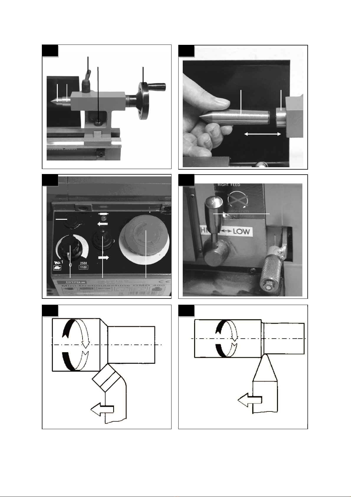
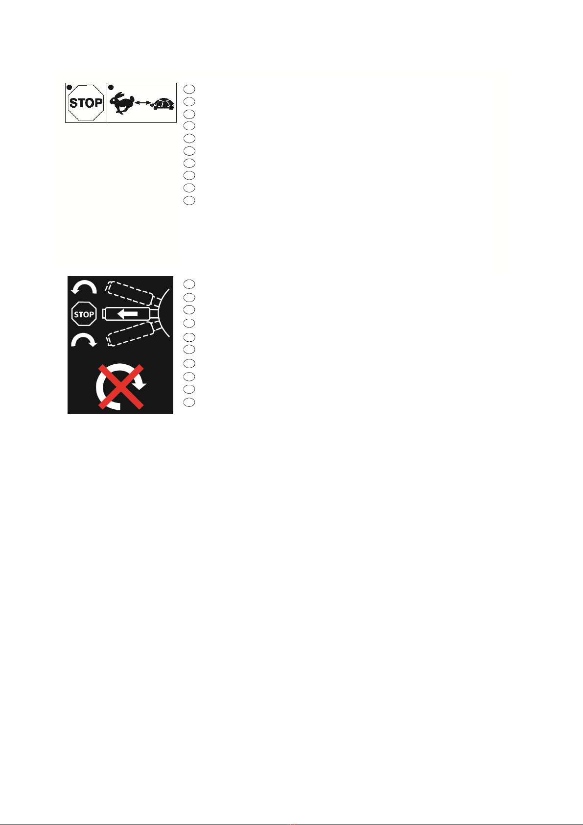
Geschwindigkeit nur im Stillstand umschalten!
Speed to be only switched when the machine is in idle state!
Commuter la vitesse uniquement en état stationnaire de la machine !
Cambiare la velocità solo con la macchina ferma!
Snelheid uitsluitend bij stilstand omschakelen!
Rychlost přepínat jen v klidovém stavu stroje!
Rýchlosť prepínať len v pokojovom stave stroja!
A sebesség kizárólag nyugalmi állapotú készülék esetében állítható!
Prędkość zmieniać tylko w stanie bezruchu!
¡Cambiar velocidad solo con el motor parado!
Drehrichtung nur im Stillstand umschalten!
Turning direction to be only switched when the machine is in idle state!
Commuter le sens des rotations seulement en état stationnaire de la machine!
Cambiare il senso di rotazione solo con la macchina ferma!
Draairichting uitsluitend bij stilstand omschakelen!
Směr otáčení přepínat jen v klidovém stavu stroje!
Rýchlosť prepínať len v pokojovom stave stroja!
Hitrost lahko preklopite, kadar stroj miruje!
Kierunek obrotow zmieniać tylko w stanie bezruchu!
¡Cambiar el sentido de giro solo con la máquina parada!
DE
EN
FR
IT
NL
CZ
SK
HU
PL
ES
DE
EN
FR
IT
NL
CZ
SK
HU
PL
ES

25
1
2
3
4
5
6
7
8
9
10
11
12
13
14
15
16
17
18
19
20
22
21
23
24
26
27
28
41
40
39 42 37
38
29
35
30
32
31
34
33
36
2
1
43

3
4
4b
4a
5
6
7
8
a
a
b
b
a
a
Ca. ø1,5 -
Ca. ø30 mm
Ca. ø20 -
Ca. ø70 mm
Ca. ø25-
Ca. ø75 mm
4 A
A
3

9
10
11 12
13 14
3
41
4
4
4
6
7
5
B 6 5
7
B
BD
33
Pos. 1
Pos. 2
Pos. 3
a
a
1

15 16
17 18
19
c
b
b
c
c
b
A
B
C
D
d
d
I
II
III
E

20 21
22 23
24 25
9 10
28 27 26
B
9 10
11
13
32
43

26 27
28 29
30 31
A
A
A
23 20
A
A B
20

32 33

# 48132
1
www.guede.com
GÜDE GmbH & Co. KG | Birkichstrasse 6 | D-74549 Wolpertshausen
Tel.: +49 (0) 79 04 / 700-360 | Fax: +49 (0) 79 04 / 700-51999 | E-Mail: suppor[email protected].com
4 x

DE
Wir bedanken uns für den Kauf einer Güde MINI-DREHMASCHINE GMD 400 und das von Ihnen
entgegengebrachte Vertrauen in unser Sortiment.
!!! Lesen Sie bitte diese Bedienungsanleitung sorgfältig durch,
bevor Sie das Gerät in Betrieb nehmen !!!
DE
Sie haben technische Fragen? Eine Reklamation? Benötigen Ersatzteile oder eine Bedienungsanleitung?
Auf unserer Homepage www.guede.com im Bereich Service helfen wir Ihnen schnell und unbürokratisch weiter. Bitte helfen Sie uns Ihnen
zu helfen. Um Ihr Gerät im Reklamationsfall identifizieren zu können benötigen wir die Seriennummer sowie Artikelnummer und Baujahr. Alle
diese Daten finden Sie auf dem Typenschild. Um diese Daten stets zur Hand zu haben, tragen Sie diese bitte unten ein.
Seriennummer:____________________________Artikelnummer:________________________Baujahr:_____________________________
Tel.: +49 (0) 79 04 / 700-360 Fax: +49 (0) 79 04 / 700-51999 E-Mail: [email protected]m
A.V. 2 Nachdrucke, auch auszugsweise, bedürfen der Genehmigung. Technische Änderungen vorbehalten. Abbildungen
ähnlich!!
Kennzeichnung:
Produktsicherheit:
Produkt ist mit den einschlägigen
Normen der Europäischen
Gemeinschaft konform
Verbote:
Verbot, allgemein (in Verbindung
mit anderem Piktogramm)
Verbot von lockeren
Kleidungsstücken!
Verbot von Schmuckstücken
Verbot von langen Haaren
Gerät nicht bei Nässe verwenden
Am Kabel ziehen verboten
Warnung:
Warnung/Achtung
Warnung vor fortschleudernden
Teilen!
Warnung vor gefährlicher
Elektrischer Spannung
Vor Reparatur-, Wartungs- und
Reinigungsarbeiten Motor
abstellen und Netzstecker
ziehen
Schutzeinrichtungen vor
Inbetriebnahme der Maschine
schließen
Schutzeinrichtungen bei
laufendem Motor nicht öffnen
oder entfernen
Gebote:
Vor Gebrauch
Bedienungsanleitung lesen
Augen- und Gehörschutz
tragen!
Sicherheitshandschuhe tragen! Staubmaske tragen!
Umweltschutz:
Abfall nicht in die Umwelt sondern
fachgerecht entsorgen.
Verpackungsmaterial aus
Pappe kann an den dafür
vorgesehen Recycling-Stellen
abgegeben werden.
Schadhafte und/oder zu
entsorgende elektrische oder
elektronische Geräte müssen an
den dafür vorgesehen Recycling-
Stellen abgegeben werden.
Verpackung:
Packungsorientierung Oben
Technische Daten:
Gewicht
Motorleistung
Vario Getriebe
Max. Werkstücklänge
Max. Werkstückhöhe
Gewicht
Gerätebeschreibung (Abb. 1+2)
1. Wechselräderkasten
2. Spannschraube Dreibackenfutter
3. Dreibackenfutter
4. Spannbacken
5. Klemmschrauben für Drehmeißel
6. Klemmhebel für Werkzeughalter
7. Werkzeughalter
8. Schutzabdeckung
9. Zentrierspitze
10. Pinole mit Skala
11. Klemmhebel für Pinole
12. Reitstock
13. Handkurbel für Pinole
14. Drehmaschinenbett
15. Maschinenwanne
16. Leitspindel
17. Kurbel mit Skala für Handzug (Oberschlitten)
18. Verzahnung für Vorschub
19. Vorschub-Arretierhebel
20. Skala zum Kegeldrehen

EN
Thank you for buying the mini lathe Güde GMD 400 and for your trust in our products.
!!! Please read the operating manual carefully before starting the machine !!!
EN
Any technical questions? Complaints? In need of spare parts or operating manual?
On our web pages www.guede.com we will help you fast and without needless bureaucracy. Please help us so we can help you. To identify
your machine in case of any claim, we need to know serial number, product number and year of production. You can find all these data on the
type label. To have them handy please write them down in here:
Serial number: Product number: Year of production:
Tel.: +49 (0) 79 04 / 700-360 Tel.: +49 (0) 79 04 / 700-360 Tel.: +49 (0) 79 04 / 700-360
A.V. 2 For reprints, even partial, permission required. Technical changes reserved. Similar pictures !!
Labeling:
Product safety:
Product complies with EU
standards
Restrictions:
General prohibition (in connection
with other icons)
Wearing loose clothing
prohibited!
Wearing jewels prohibited
No long hair
Machine not to be used in wet
conditions
Pulling the cable prohibited
Warnings:
Warning/Caution
Warning against thrown-off
items!
Warning against dangerous
voltage
Engine to be switched off and
system plug to be disconnected
before any repair, servicing or
cleaning
Protective equipment to be closed
before putting the machine into
operation
Protective equipment not to be
opened or removed when the
engine is running
Commands:
Please read the Operating
Instructions before using the
machine
Eye and ear protection to be
used!
Protective gloves to be worn! Protective mask against dust to
be worn!
Environmental protection:
Dispose the waste professionally.
Do not litter.
Packing material made of
cardboard can be disposed in
scrap-yards.
Malfunctioning and/or disposed
electric or electronic devices must
be disposed to authorized scrap-
yards.
Package:
This side up
Technical specifications:
Connection
Engine power
Vario gearbox
Max. workpiece length
Max. workpiece height
Weight
Machine description (pic. 1+2)
1. Gearbox with sprocket wheels
2. Three-jaw chuck fastening screw
3. Three-jaw chuck
4. Chuck jaw
5. Catches for lathe tool
6. Chucking lever for tool holder
7. Tool holder
8. Protective cover
9. Centring point
10. Sleeve with scale
11. Chucking level for quill
12. Tailstock
13. Hand lever for sleeve
14. Lathe bed
15. Machine bath
16. Guide screw
17. Crank with scale for manual feed (knife slide)
18. Toothing for feed
19. Feed blocking lever
20. Scale for angular turning

21. Crank with scale for transverse feed (surfacing slide)
22. Surfacing slide
23. Knife slide
24. Bed slide
25. Hand wheel for sliding traverse
26. Safety switch (Not-Aus)
27. Turning direction selector
28. Speed controller
29. Rear protective wall against spraying
30. Engine housing
31. Switch protective cover
32. Fast / slow speed selector
33. Power cord
34. Feed direction lever
35. Headstock
36. Three-jaw chuck protective cover
37. Sprocket wheels
38. Oil bottle
39. Chuck jaws
40. Allen wrench
41. Jaw chuck wrench
42. Fork wrench
Supply includes
9 sprocket (exchangeable) gear wheels
Fork wrench
Hexagonal wrench
Oil bottle
Centring point
Three-jaw chuck
Exchangeable jaws
Machine
For turning and cutting of threads of structural steel,
nonferrous metals, plastic material or wood, grooved guide
with optional adjustment, drive transmission using stepped
pulleys and sprocket wheels (feed screw), right/left running,
electrical switching, automatic feed mechanism, continuous
speed control.
Warranty
A warranty period of 12 months applies to commercial use
and 24 months apply to private use and commences on
the day of purchase of the device.
Warranty applies exclusively to failures due to defective
material or workmanship. An original sale slip with
indication of date of sale must be presented in case of
claiming for the warranty rights.
Warranty does not cover unprofessional use such as
device overload, violent use, damage caused by third party
or foreign materials, failure to comply with operations and
assembly manual, and normal wear and tear.
Technical specifications
Engine wiring: 230V~50Hz
P1 engine power: 370 W
Max. workpiece length: 300 mm
Max. workpiece height: 180 mm
Point height: 90 mm
Spindle boring-Ø: 20 mm
Max. workpiece Ø – over bed: 180 mm
Work spindle: MK3
Tailstock spindle: MK2
Jaw chuck boring: 15 mm
Centred running accuracy: 0.01 mm
Speed, level 1: 0-1,100 per min-
1
Speed, level 2: 0-2,500 per min-
1
Lathe tool mounting: 8x8 mm
Weight: 35 kg
General safety instructions
Please read carefully the safety regulations below and
the Operating Instructions before using the machine.
Before the machine is used by other persons, they must
be familiarised with these Operating Instructions. Keep
the Instructions for future reference!
Package: The machine is in a package for purposes of
protection against damage during transport. The
packages are raw materials subject to recycling or
returning back to circulation.
Please read carefully this manual and follow the
instructions included. Use the manual to get acquainted
with the machine, learn how to use it properly and
familiarise with the safety instructions. Keep the safety
instructions for future reference.
Unplug the machine before any work on it.
Use the machine in accordance with the given
purpose of use.
Safety in the place of work is your responsibility.
Work under adequate light conditions only.
Never leave the machine unattended.
Keep the machine in a safe place after finishing
your work.
Never expose the machine to rain and moist or wet
conditions.
Protect the machine against moisture and rain.
Do not switch the machine on when turned or, to be
more specific, not in the working position.
Keep the machine in a dry place inaccessible by
children when not being used.
All machine parts must be regularly inspected for
any sign of damage or aging. The machine must not
be used when not in a perfect state.
Original spare parts to be used for servicing.
Repairs may only be executed by a professional
electrician.
Before putting the machine into operation and after
any impact, check the machine for any sign of wear
or damage and have any repair executed.
Never use any spare part or accessories not
specified or recommended by the manufacturer.
Make sure no other items cause short-circuit on the
machine contacts.
Before wiring, make sure the details on the type label
correspond to the system details.
The machine is no toy for children! Children are not
able to estimate the machine-related risk. Children
must not use the machine in any case.
Persons who are not able to operate the machine due
to their physical, sensory or mental skills or due to
inexperience or absence of knowledge must not use
the machine.
If there is any sign of visible damage to the machine,
it must not be put into operation.
Serious risks may arise as a result of unauthorised
repairs.
The same regulations apply to accessories.
Güde GmbH & Co. KG will not assume any liability for
damage caused as a result of the following:
Machine damage by mechanical influences and
overvoltage.
Changes to the machine
Use for purposes other than those specified in the
Operating Instructions.
It is necessary to follow all safety instructions to
prevent injuries and damage.

Machine-specific safety instructions
1. Safety shoes, eye and ear protection to be used AT
ALL TIMES.
2. Do not wear any loose-fitting clothes (ties, jewels,
etc.). Long hair should be tied.
3. Make sure your hands can move freely when
operating the machine so that working is safe.
4. Unplug the machine before any work on it.
5. Never check the machine or take any measure in
respect of the machine until the lathe spindle is fully
stopped.
6. Speed may only be changed when the lathe spindle
is fully stopped.
7. Make sure the surface is able to withstand the
machine weight.
8. At all times, close the protective covers before
switching the machine on.
Use as designated
The lathe can be used both for outdoor and indoor turning
work, face turning, thread turning and a broad range of
various activities such as boring, reaming and cutting of
threads. The lathe can be used in precision mechanics and
do-it-yourself work, guaranteeing good results.
Disposal
Disposal instructions are illustrated in the form of
pictograms on the device or packaging. Description of the
pictograms is given in "Identification" chapter.
Disposal of transport packaging
Packaging protects the device against damage during
transport. Packaging materials are usually selected
according to their effect on environment and disposal
methods and can therefore be recycled.
Returning of the packaging back to circulation saves
resources and costs for packaging disposal.
Parts of the packaging (e.g. foil, styropor) may be
dangerous for children. Risk of suffocation!
Keep these parts of the packaging out of reach of children
and dispose as soon as possible.
Operator requirements
The operator should carefully read the Operating
Instructions before using the machine.
Residual risks and protective measures
Even if this electric machine is operated in accordance
with the applicable rules and regulations, some residual
risks still exist.
The following risks may arise in connection with the design
of this electric machine:
1. Damage to lungs if an appropriate mask for the
protection against dust is not worn.
2. Hearing damage if appropriate hearing protection is not
used.
3. Damage to health arising from vibration affecting hands
and shoulders if the machine has been used for a long
time or is not properly maintained.
4. Direct electric contact
A defective cable or plug may lead to electric shock
dangerous to life.
At all times, have any defective cable or plug replaced
by an expert. Only a machine connected to a safety
switch against stray current to be used.
5. Indirect electric contact
Injury by live parts in case of exposed electric or
defective structural parts.
System plug to be always disconnected before any
servicing. Work on RCD switches only.
6. Inappropriate local lighting, inadequate lighting
represent a high safety risk.
At all times, provide appropriate and adequate lighting
for your work with the machine.
Qualification
There is no need for any special qualification except for
detailed training by qualified person.
Minimum age
Operate the machine can only people 16+ years old.
Exception is made when using by youths during the
occupational training to achieve exact skills under the
supervision of a trainer.
Training
There is a corresponding course needed only to operate
this machine. No special training is necessary.
Putting the machine into operation
Before putting the machine into operation, check
thoroughly if the electrical equipment installation is
appropriate and if the connections on connection spots
are tight. Lines/cables could get loose during transport,
resulting in a risk of injury when connected to the
power supply.
The guiding surfaces of the machine bed and all
exposed parts are treated with anti-corrosive agents
for transport purposes. The anti-corrosive agents can
be removed by paraffin or petrol for washing purposes.
Then, dry out the machine bed surfaces and lubricate
the guide with oil for the bed guiding surfaces.
Check all controls if their controllability is smooth and if
they can be moved smoothly backlash free. If the
guides are difficult to use, get stuck or their backlash is
too big, they must be adjusted with the adjustment
mouldings and pressure pins.
All controls must be checked for continuous
controllability and slide and transverse guiding of bed
slides, surfacing slides for continuous movement
without any backlash. If guiding was difficult, got stuck
or had a too big backlash, it is necessary to make an
adjustment using the adjustment mouldings and
pressure pins.
Before putting the machine into operation, check
thoroughly if the electrical equipment installation is
appropriate and if the connections on connection spots
are tight.
All the safety equipment and covers must be fitted
before the machine is put into operation.
To put the machine into operation for the first time, set
the lowest spindle speed and run the machine without
any load for at least 10 minutes. Watch the bearings,
etc. if not getting abnormally hot and follow the
function process, noise, etc. If no anomaly is found,
the spindle speed can gradually be increased to the
maximum level.
All interfaces, lubrication holes and surfaces on the
machine to be lubricated should be treated with
lubrication oil.
Installation / Change of chuck jaws (pic. 3-10/pos.4)
The chuck jaws (4) are numbered 1 to 3 and must be fitted
in the chuck jaw guiding based on the order (A) in the
three-jaw chuck (3).
First, insert the jaw chuck key (41) in one of the
fastening screws of the three-jaw chuck (2) and loosen
the chuck jaw (4) by turning the jaw chuck key (41) to
the left until the chuck jaw (26) can be released
(picture 3).
Choose the chuck jaws to be installed (see Inner and
outer grade of chuck jaws) and sort them by their
numbering (a numerical code starting with 1, 2 or 3 is
imprinted on every chuck jaw) (pic. 4-7).
Put the chuck jaw 1 to one of the chuck jaw guiding (A)
and press it towards the centre of the three-jaw chuck
(3).

Now turn the jaw chuck key (41) to the left until the
chuck jaw 1 slips a little bit towards the centre of the
three-jaw chuck (3) (picture 8).
Now fit in chuck jaws 2 and 3 clockwise to the other
two chuck jaw guidings (A).
Press all 3 chuck jaws (4) to each other and clamp the
three-jaw chuck (3) by turning the jaw chuck key (41)
to the right – pictures 17 – 19.
Inside the three-jaw chuck there is a thread interfering
with the notches on the back of the chuck jaws (4), by
which they are clamped together (picture 9).
Check if the clamping of the chuck jaws (4) is centred
by turning the chuck jaws (4) fully to each other using
the jaw chuck key (4). If not all chuck jaws (4) fit tight
to the centre, they must be fitted again (picture 10).
Inner and outer grade of chuck jaws
(picture 4 – 7/pos.4)
Workpieces with a diameter of up to app. 70 mm are
clamped on their outside diameter (picture 7). Workpieces
with an outside diameter of 1.5-30 mm can be clamped
with outwardly graded chuck jaws (a) (picture 5).
Workpieces with boring of at least 25 mm can be clamped
using outwardly graded chuck jaws (a) in boring (picture
6). Workpieces with a diameter of up to app. 70 mm can
be clamped if outwardly graded chuck jaws (a) are
changed for inwardly graded chuck jaws (b).
Caution:
Workpieces must be clamped in a sufficient depth in the
three-jaw chuck (3). Take the jaw chuck key (41) out.
Make sure the workpiece is clamped firmly.
Caution:
Make sure the outer jaws are still held by the spiral thread
and are not screwed out too much!
Lathe tool clamping (pic. 11 - 12)
The lathe tool (B) is clamped by at least two clamping
screws (5) in the tool holder (7). Clamp the lathe tool (B)
as short as possible so that the lever (D) path is also as
short as possible. Make sure the adjustment height is
correct. The height position of the lathe tool (B) is achieved
by putting variously thick flat sheets (C) underneath. The
height position on the centre of the workpiece is checked
based on the centring point (9) on the tailstock (12). The
tool holder (7) can be turned by loosening the clamp lever
(6) and adjusted to any other working position. Up to 4
lathe tools (B) can be clamped in the tool holder (7) at the
same time. The lathe tools can be switched by turning the
tool holder (7).
Caution:
The lathe tool (B) must be clamped with its axis vertically
to the workpiece axis. If clamped sideways, the lathe tool
(B) can be drawn in the workpiece.
Feed direction selection (pic. 13)
The guide screw (16) turning direction can be selected on
the feed direction lever (34) on the back of the machine.
Pos. 1 Up: Left feed direction
Pos. 2 Middle: Feed direction off
Pos. 3 Down: Right feed direction
Feed pace, change of sprocket wheels (pic. 14-19)
To achieve various feed paces, the appropriate sprocket
wheels must be chosen.
Loosen the clamping screws (a) on the sprocket wheel
box (1) and remove it (pic. 14).
Loosen the clamping screws (d) of the shafts of the
gear wheels and remove the sprocket wheels
(c) from the shafts (picture 15).
Loosen the clamping nuts of the balancing holder of
the gear wheels (picture 16/pos. d).
Choose the necessary sprocket wheels as shown in
pictures 17 – 19.
The table (picture 19) shows the necessary number of
teeth (F) of the sprocket wheels for the appropriate
feed in mm for one turning (E).
Fit the gear wheels to the appropriate shafts of the
gear wheels and secure them using the clamping
screws (picture 15/pos. b).
If gear wheels A, B and D are only needed for the
necessary transmission, a clamping sleeve (E) shown
in picture 18 must be fitted on the shaft III before the
gear wheel.
Adjust the balancing holder of the gear wheel and the
shaft of the gear wheels in a way the gear wheels can
be moved with light backlash. Now tighten the
clamping nuts of the balancing holder of the gear
wheels (d) (picture 16).
Important: To switch the machine on, the cover of the
box of the sprocket wheels (picture 14 / pos. 1) must
be fitted.
Tailstock adjusting (pic. 1 and 20)
The tailstock (12) can be moved in the lathe bed (14) back
and forth.
For that purpose, loosen the tailstock clamping
nut (43, key 42) and move the tailstock to the
required position.
Then, tighten the tailstock clamping nut properly
(43, key 42).
Sleeve installation/removal/adjusting (pic. 12-21)
The sleeve (10) holds the centring point (9). It is used to
clamp and check long workpieces. The sleeve (10) can be
adjusted back and forth using the hand crank (13). The
sleeve (10) is clamped or locked in the required position
using the clamp lever (11). The rear side of the centring
point (9) is conical and is held by locking in in the sleeve
(10). To remove the centring point (9), loosen the chucking
lever (11) and use the hand crank (13) to adjust the sleeve
(10) fully to the back. By this, the centring point (9) is
pushed out of its clamping and can be taken out. To use it,
insert the centring point (9) in the sleeve (10). When
chucked, the workpiece is automatically clamped in the
sleeve (10).
Instead of the centring point (9), a bore in the appropriate
cone can also be inserted in the sleeve (10) for example
as preparation/roughening for inner turning. There is a
scale on the sleeve (10) showing how deep it is being
bored to the workpiece.
Three-jaw chuck protective cover (pic. 2 / pos.36)
The three-jaw chuck protective cover (36) is used for the
protection of the user. It must always be folded down when
operating the machine. When the protective cover (36) is
folded up, the machine cannot be switched on, as the
safety switch (picture 2 / pos. 31) in the back is not
controlled.
Cranks for transverse and manual run (pic. 1 / pos. 21,
resp. 17)
When turning, the lathe tool is guided along the workpiece
using cranks for transverse and manual running.
On both cranks there are indexing wheels with a scale that
are adjusted to 0 when the lathe tool touches the
workpiece. By this, the depth of turnings removal can be
measured.
To adjust the indexing wheels with a scale to 0, loosen the
handrail bolts in the indexing wheels, turn them to 0 and
tighten the handrail bolts again.
Operating the machine
Switching the machine on and off (picture 22)
Switching the machine on
Please follow this order when switching the lathe on!
First, fold down the protective cover (36) above the
three-jaw chuck (3) (three-jaw chuck protective
cover).
The speed controller (2) must first be in the zero
position (marking in the very bottom) whenever the
machine is being switched on or when changing the
speed direction.
Now choose the desired turning direction on the
turning direction selector (27) (L=left running / R= right
running).
Make sure the safety switch (Not-Aus) is not pressed.
Now the machine can be switched on by controlling
the speed selector (28).

Switching the machine off
To switch the machine off, turn the speed controller (28) to
the “zero position“.
Emergency stop
To switch the machine quickly and easily off, e.g. in case
of emergency, press the safety switch (Not-Aus) (pic. 22 /
pos. 26). To put the machine into operation again, the
safety switch (Not-Aus) must be released.
Caution:
Before any change of the turning direction, it is necessary
to wait until the machine fully stops as, otherwise, the
machine could get damaged! To prevent machine
overloading, changing down to lower speed before
switching the machine on is necessary for a work with high
speed. When the machine gets overloaded or blocked, the
control is automatically switched off.
Unplug the machine if it is not going to be used
for a long time or before any adjusting or servicing.
Speed adjusting (picture 22 – 23)
Machine speed can smoothly be adjusted using the speed
controller (28). The speed range can be preset on the
speed switch (32).
Speed switch in the “Hase“ (Fast) position:
Revolutions: 0-2,500 per min-1
Speed switch in the “Schildkröte“ (Slow) position:
Revolutions: 0-1,100 per min-1
Cooling
Heat by friction is produced on the lathe tool edge when
turning. To increase the life of the lathe tool and improve
the cut profile, the lathe tool must be cooled during work.
For this, use the attached oil bottle (38) and the
environment-friendly water-soluble boring emulsion.
Turning
General
Clamp the lathe tool firmly in the tool holder (7) (see
Lathe tool clamping)
Clamp the workpiece firmly and as deep in the three-
jaw chuck (3) as possible.
Check whether the workpiece is running cylindrically.
Make sure the feed is deactivated (except for turning
of threads).
Switch the machine on (see Switching the machine
on and off).
Slide turning (pic. 1, 24 – 25)
The lathe tool moves in parallel to the workpiece axis
during slide turning.
For slide turning from right to the left, first turn the bed
slide (24) using the hand wheel for sliding traverse (25)
so much to the left and the knife slide (23) using the
crank for manual run (17) so much to the right that the
travel path of the knife slide (23) is enough for the
entire machining length.
Put the feed direction lever (33) to position 2, the feed
mechanism will get deactivated and fixate the bed
slide (24) using the feed blocking lever (19).
Turn the crank for traverse motion (21) to go with the
surfacing slide (22) so much to the back that the lathe
tool does not touch the workpiece circumference.
Now use the crank for manual run (17) to adjust the
knife slide (23) so that the lathe tool point is above the
longest diameter of the workpiece.
Turn the crank for traverse motion to go slowly with the
surfacing slide (22) to the workpiece until the lathe tool
slightly touches the workpiece surface.
This is now the initial position for machining the
outside diameter of your workpiece.
The scale division on the crank for traverse motion (8)
corresponds to 0.05 mm of the workpiece diameter
(cut depth 0.025 mm).
Optional automatic feed during slide turning by
connecting the feed blocking lever (19).
Caution:
Before switching the machine on, make sure the feed
direction lever (33) is in position 2 and the feed mechanism
deactivated (see Feed direction selection).
Transverse turning (pic. 1, 26)
Transverse turning is done similarly as the slide turning.
The lathe tool moves to the centre of the workpiece axis
during the transverse turning.
During face machining, the main edge of the lathe tool
must be adjusted precisely to the workpiece centre to
make sure there is no extension in the centre of the
workpiece. Adjust the lathe tool according to the centring
point (9).
The workpiece is turned from outside to the inside during
the transverse turning with a bent lathe tool or facing lathe
tool while it is from inside out during transverse turning
with an angle-cutting tool or side lathe tool.
Inner turning
Inner turning of boring is done similarly as the transverse
and slide turning. As in most cases the lathe tool cannot be
seen in the boring operation, a special care must be
exercised. For inner turning, a borer for workpiece
preboring instead of the centring point (9) is clamped (see
Sleeve installation/removal/adjusting).
Recessing and parting
When recessing and parting, the lathe tool moves to the
centre of the workpiece axis.
A recessing tool is used for recessing while a parting tool
is used for parting.
Caution:
During slide, transverse, inner turning, recessing and
parting make sure the lathe tool is precisely adjusted to the
centre.
Turning of conical surfaces (pic. 27 - 28)
Conical surfaces are turned by adjusting the knife slide
(23). After loosening the adjusting screws (A), the knife
slide turns around its axis (pic. 28).
Cone adjustment is done according to the scale for turning
of conical surfaces (20).
The adjusting screws (A) must be tightened again after
correct adjustment of the tool-holding slide (pic. 29).
Turning of threads (pic. 29)
Threads are turned using a special tool for cutting threads.
The tool is clamped perpendicularly to the workpiece axis.
This can best be done using the lathe tool gauge (pic. 30 /
pos. A) When turning threads, feed is provided by the
guide screw (16) and it must correspond to the thread
lead. For this purpose, the feed pace is adjusted by the
correct selection of the sprocket wheels (see Feed pace,
change of sprocket wheels).
Caution:
Work at low speed and with good lubrication when cutting
a thread. The feed blocking lever (19) must not get opened
and the workpiece must not be taken out of the jaw chuck
when cutting a thread and between cutting operations
when turning a thread.
Cleaning
Cleaning, servicing and ordering of spare parts
Disconnect the plug before any cleaning.
Cleaning
We recommend cleaning the machine after every use.
Remove turnings using a brush.
Remove any dirt, remains of lubricants and oil using a
cotton cloth.
Never use compressed air for cleaning.
After cleaning, apply an acid-free lubricant on the
metal parts.
Changing the drive belt (pic. 30 - 33)
The drive belt is a part subject to quick wear. It must be
changed if necessary. First, remove the sprocket wheel
box cover (1) and the sprocket wheels (see Feed pace,
change of sprocket wheels). Now loosen both holding

screws (pic. 30/ pos. A) and take the transmission plate
(pic. 31/ pos. B) out.
Remove the drive belt when the upper gear wheel is
turning and take it out of the engine shaft (pic. 32 – 33).
Installation in a reversed order.
Important: To switch the machine on, the sprocket wheel
box cover (picture 14/pos.4) must be fitted.
Caution:
To change the cogged belt, switch the machine off and
disconnect it from the power source.
Changing the machine fuse (pic. 22/ pos. B)
Caution! Switch the machine off and disconnect it
from the power source!
If the lathe is not working, check the fuse in the fuse holder
(B) and change it for a new one with the same nominal
value if necessary.
Slide backlash adjusting
If there is a too big backlash in guiding of the slide, you
can adjust it using the handrail bolts secured by a lock nut
on the side of the slide.
Caution:
Reverse backlash in the feed spindles up to one and a half
revolutions is conditioned by the design.
Carbon brushes
Have the carbon brushes checked by a professional
electrician if sparks are produced excessively.
Caution! Carbon brushes may only be changed by
a professional electrician.
Transport and storing
For machine transport, the bed slide must be moved to the
end of the bed near the tailstock where the bed slide will be
clamped.
Servicing and maintenance
System plug to be disconnected before any
servicing or maintenance!
Continuous maintenance must be provided when using the
machine. By this, high operating accuracy and reliability will
be kept for a long time of using the machine.
1. Use a brush to remove the turnings.
2. All moving parts must be lubricated before and after
operating the machine.
3. The slide and guide surfaces must be continuously
cleaned to remove turnings and the metal abrasion,
especially when machining grey cast iron, brass, bronze,
aluminium and lubricated again. Surfaces not to be
cleaned by compressed air. Use a brush or vacuum for
cleaning.
4. Check if the metal abrasion is not present on the felt
wipers between the guide surfaces. Remove the metal
abrasion, clean the felt wipers, refit them so that they fit
tightly to the guide surfaces from all sides. Lubricate the
felt and the guide surfaces.
5. To maintain the high machine accuracy, the centres,
guide surfaces, feed spindle, etc. must be treated with
due care.
If any damage is identified when inspecting the
machine, it must be immediately removed.
Maintenance plan (image no. 4)
APPLY ONLY LUBRICATING GREASE FREE OF RESIN AND ACIDS ON FRICTION AND ANTI-FRICTION BEARINGS!
Machine part Frequency Lubricating grease type
Guide spindle After each use Pre-clean with detergent and spray oil,
then apply the lubricant grease
Friction bearings of the guide
spindle
1x per month or after 10 hours of duty Lubricant grease
Machine bed, dog chuck,
machine surface After each use Detergent and spray oil
Bearing shell and shaft of the
shifting wheels transmission Upon each shifting wheel replacement or after 10
hours of duty Lubricant grease
Guide screw nut 1x per month or after 10 hours of duty Lubricant grease
Sliding spindle of the
transverse sliders with
adjustable bolt nut
1x per month or after 10
hours of duty Lubricant grease
Sliding spindle of the bed slides 1x per month or after 10 hours of duty Lubricant grease
Sliding spindle of the quill 1x per 3 months or after 30 hours of duty Lubricant grease

EN
Thank you for buying the mini lathe Güde GMD 400 and for your trust in our products.
!!! Please read the operating manual carefully before starting the machine !!!
EN
Any technical questions? Complaints? In need of spare parts or operating manual?
On our web pages www.guede.com we will help you fast and without needless bureaucracy. Please help us so we can help you. To identify
your machine in case of any claim, we need to know serial number, product number and year of production. You can find all these data on the
type label. To have them handy please write them down in here:
Serial number: Product number: Year of production:
Tel.: +49 (0) 79 04 / 700-360 Tel.: +49 (0) 79 04 / 700-360 Tel.: +49 (0) 79 04 / 700-360
A.V. 2 For reprints, even partial, permission required. Technical changes reserved. Similar pictures !!
Labeling:
Product safety:
Product complies with EU
standards
Restrictions:
General prohibition (in connection
with other icons)
Wearing loose clothing
prohibited!
Wearing jewels prohibited
No long hair
Machine not to be used in wet
conditions
Pulling the cable prohibited
Warnings:
Warning/Caution
Warning against thrown-off
items!
Warning against dangerous
voltage
Engine to be switched off and
system plug to be disconnected
before any repair, servicing or
cleaning
Protective equipment to be closed
before putting the machine into
operation
Protective equipment not to be
opened or removed when the
engine is running
Commands:
Please read the Operating
Instructions before using the
machine
Eye and ear protection to be
used!
Protective gloves to be worn! Protective mask against dust to
be worn!
Environmental protection:
Dispose the waste professionally.
Do not litter.
Packing material made of
cardboard can be disposed in
scrap-yards.
Malfunctioning and/or disposed
electric or electronic devices must
be disposed to authorized scrap-
yards.
Package:
This side up
Technical specifications:
Connection
Engine power
Vario gearbox
Max. workpiece length
Max. workpiece height
Weight
Machine description (pic. 1+2)
1. Gearbox with sprocket wheels
2. Three-jaw chuck fastening screw
3. Three-jaw chuck
4. Chuck jaw
5. Catches for lathe tool
6. Chucking lever for tool holder
7. Tool holder
8. Protective cover
9. Centring point
10. Sleeve with scale
11. Chucking level for quill
12. Tailstock
13. Hand lever for sleeve
14. Lathe bed
15. Machine bath
16. Guide screw
17. Crank with scale for manual feed (knife slide)
18. Toothing for feed
19. Feed blocking lever
20. Scale for angular turning

21. Crank with scale for transverse feed (surfacing slide)
22. Surfacing slide
23. Knife slide
24. Bed slide
25. Hand wheel for sliding traverse
26. Safety switch (Not-Aus)
27. Turning direction selector
28. Speed controller
29. Rear protective wall against spraying
30. Engine housing
31. Switch protective cover
32. Fast / slow speed selector
33. Power cord
34. Feed direction lever
35. Headstock
36. Three-jaw chuck protective cover
37. Sprocket wheels
38. Oil bottle
39. Chuck jaws
40. Allen wrench
41. Jaw chuck wrench
42. Fork wrench
Supply includes
9 sprocket (exchangeable) gear wheels
Fork wrench
Hexagonal wrench
Oil bottle
Centring point
Three-jaw chuck
Exchangeable jaws
Machine
For turning and cutting of threads of structural steel,
nonferrous metals, plastic material or wood, grooved guide
with optional adjustment, drive transmission using stepped
pulleys and sprocket wheels (feed screw), right/left running,
electrical switching, automatic feed mechanism, continuous
speed control.
Warranty
A warranty period of 12 months applies to commercial use
and 24 months apply to private use and commences on
the day of purchase of the device.
Warranty applies exclusively to failures due to defective
material or workmanship. An original sale slip with
indication of date of sale must be presented in case of
claiming for the warranty rights.
Warranty does not cover unprofessional use such as
device overload, violent use, damage caused by third party
or foreign materials, failure to comply with operations and
assembly manual, and normal wear and tear.
Technical specifications
Engine wiring: 230V~50Hz
P1 engine power: 370 W
Max. workpiece length: 300 mm
Max. workpiece height: 180 mm
Point height: 90 mm
Spindle boring-Ø: 20 mm
Max. workpiece Ø – over bed: 180 mm
Work spindle: MK3
Tailstock spindle: MK2
Jaw chuck boring: 15 mm
Centred running accuracy: 0.01 mm
Speed, level 1: 0-1,100 per min-
1
Speed, level 2: 0-2,500 per min-
1
Lathe tool mounting: 8x8 mm
Weight: 35 kg
General safety instructions
Please read carefully the safety regulations below and
the Operating Instructions before using the machine.
Before the machine is used by other persons, they must
be familiarised with these Operating Instructions. Keep
the Instructions for future reference!
Package: The machine is in a package for purposes of
protection against damage during transport. The
packages are raw materials subject to recycling or
returning back to circulation.
Please read carefully this manual and follow the
instructions included. Use the manual to get acquainted
with the machine, learn how to use it properly and
familiarise with the safety instructions. Keep the safety
instructions for future reference.
Unplug the machine before any work on it.
Use the machine in accordance with the given
purpose of use.
Safety in the place of work is your responsibility.
Work under adequate light conditions only.
Never leave the machine unattended.
Keep the machine in a safe place after finishing
your work.
Never expose the machine to rain and moist or wet
conditions.
Protect the machine against moisture and rain.
Do not switch the machine on when turned or, to be
more specific, not in the working position.
Keep the machine in a dry place inaccessible by
children when not being used.
All machine parts must be regularly inspected for
any sign of damage or aging. The machine must not
be used when not in a perfect state.
Original spare parts to be used for servicing.
Repairs may only be executed by a professional
electrician.
Before putting the machine into operation and after
any impact, check the machine for any sign of wear
or damage and have any repair executed.
Never use any spare part or accessories not
specified or recommended by the manufacturer.
Make sure no other items cause short-circuit on the
machine contacts.
Before wiring, make sure the details on the type label
correspond to the system details.
The machine is no toy for children! Children are not
able to estimate the machine-related risk. Children
must not use the machine in any case.
Persons who are not able to operate the machine due
to their physical, sensory or mental skills or due to
inexperience or absence of knowledge must not use
the machine.
If there is any sign of visible damage to the machine,
it must not be put into operation.
Serious risks may arise as a result of unauthorised
repairs.
The same regulations apply to accessories.
Güde GmbH & Co. KG will not assume any liability for
damage caused as a result of the following:
Machine damage by mechanical influences and
overvoltage.
Changes to the machine
Use for purposes other than those specified in the
Operating Instructions.
It is necessary to follow all safety instructions to
prevent injuries and damage.

Machine-specific safety instructions
1. Safety shoes, eye and ear protection to be used AT
ALL TIMES.
2. Do not wear any loose-fitting clothes (ties, jewels,
etc.). Long hair should be tied.
3. Make sure your hands can move freely when
operating the machine so that working is safe.
4. Unplug the machine before any work on it.
5. Never check the machine or take any measure in
respect of the machine until the lathe spindle is fully
stopped.
6. Speed may only be changed when the lathe spindle
is fully stopped.
7. Make sure the surface is able to withstand the
machine weight.
8. At all times, close the protective covers before
switching the machine on.
Use as designated
The lathe can be used both for outdoor and indoor turning
work, face turning, thread turning and a broad range of
various activities such as boring, reaming and cutting of
threads. The lathe can be used in precision mechanics and
do-it-yourself work, guaranteeing good results.
Disposal
Disposal instructions are illustrated in the form of
pictograms on the device or packaging. Description of the
pictograms is given in "Identification" chapter.
Disposal of transport packaging
Packaging protects the device against damage during
transport. Packaging materials are usually selected
according to their effect on environment and disposal
methods and can therefore be recycled.
Returning of the packaging back to circulation saves
resources and costs for packaging disposal.
Parts of the packaging (e.g. foil, styropor) may be
dangerous for children. Risk of suffocation!
Keep these parts of the packaging out of reach of children
and dispose as soon as possible.
Operator requirements
The operator should carefully read the Operating
Instructions before using the machine.
Residual risks and protective measures
Even if this electric machine is operated in accordance
with the applicable rules and regulations, some residual
risks still exist.
The following risks may arise in connection with the design
of this electric machine:
1. Damage to lungs if an appropriate mask for the
protection against dust is not worn.
2. Hearing damage if appropriate hearing protection is not
used.
3. Damage to health arising from vibration affecting hands
and shoulders if the machine has been used for a long
time or is not properly maintained.
4. Direct electric contact
A defective cable or plug may lead to electric shock
dangerous to life.
At all times, have any defective cable or plug replaced
by an expert. Only a machine connected to a safety
switch against stray current to be used.
5. Indirect electric contact
Injury by live parts in case of exposed electric or
defective structural parts.
System plug to be always disconnected before any
servicing. Work on RCD switches only.
6. Inappropriate local lighting, inadequate lighting
represent a high safety risk.
At all times, provide appropriate and adequate lighting
for your work with the machine.
Qualification
There is no need for any special qualification except for
detailed training by qualified person.
Minimum age
Operate the machine can only people 16+ years old.
Exception is made when using by youths during the
occupational training to achieve exact skills under the
supervision of a trainer.
Training
There is a corresponding course needed only to operate
this machine. No special training is necessary.
Putting the machine into operation
Before putting the machine into operation, check
thoroughly if the electrical equipment installation is
appropriate and if the connections on connection spots
are tight. Lines/cables could get loose during transport,
resulting in a risk of injury when connected to the
power supply.
The guiding surfaces of the machine bed and all
exposed parts are treated with anti-corrosive agents
for transport purposes. The anti-corrosive agents can
be removed by paraffin or petrol for washing purposes.
Then, dry out the machine bed surfaces and lubricate
the guide with oil for the bed guiding surfaces.
Check all controls if their controllability is smooth and if
they can be moved smoothly backlash free. If the
guides are difficult to use, get stuck or their backlash is
too big, they must be adjusted with the adjustment
mouldings and pressure pins.
All controls must be checked for continuous
controllability and slide and transverse guiding of bed
slides, surfacing slides for continuous movement
without any backlash. If guiding was difficult, got stuck
or had a too big backlash, it is necessary to make an
adjustment using the adjustment mouldings and
pressure pins.
Before putting the machine into operation, check
thoroughly if the electrical equipment installation is
appropriate and if the connections on connection spots
are tight.
All the safety equipment and covers must be fitted
before the machine is put into operation.
To put the machine into operation for the first time, set
the lowest spindle speed and run the machine without
any load for at least 10 minutes. Watch the bearings,
etc. if not getting abnormally hot and follow the
function process, noise, etc. If no anomaly is found,
the spindle speed can gradually be increased to the
maximum level.
All interfaces, lubrication holes and surfaces on the
machine to be lubricated should be treated with
lubrication oil.
Installation / Change of chuck jaws (pic. 3-10/pos.4)
The chuck jaws (4) are numbered 1 to 3 and must be fitted
in the chuck jaw guiding based on the order (A) in the
three-jaw chuck (3).
First, insert the jaw chuck key (41) in one of the
fastening screws of the three-jaw chuck (2) and loosen
the chuck jaw (4) by turning the jaw chuck key (41) to
the left until the chuck jaw (26) can be released
(picture 3).
Choose the chuck jaws to be installed (see Inner and
outer grade of chuck jaws) and sort them by their
numbering (a numerical code starting with 1, 2 or 3 is
imprinted on every chuck jaw) (pic. 4-7).
Put the chuck jaw 1 to one of the chuck jaw guiding (A)
and press it towards the centre of the three-jaw chuck
(3).
Other manuals for GMD 400
1
Table of contents
Other Gude Lathe manuals
Popular Lathe manuals by other brands

PSI Woodworking
PSI Woodworking Turncrafters Commander KWL1018VS user manual

Puhui
Puhui MT-602 user manual

Teknatool
Teknatool nova Neptune DVR Operation manual

Woodstar
Woodstar wl 05 Translation from the original instruction manual

WoodFast
WoodFast M320 instruction manual

Grizzly
Grizzly T10096 instructions