Estate Slide E-SL 450 Series User manual

Instruction Manual for the
E-SL 450 Series

Estate Slide Summary of Functions
The Estate Slide is only to be used for vehicular Slide gates in a Class I
setting.
Class I: A vehicular gate opener (or system) intended for use in a home of one
-to-four single family dwelling, or a garage or parking area associated therewith.
The Estate Slide automated system was designed and built for controlling vehicle
access. Do not use for any other purpose.
The Estate Slide automated system automates residential slide-leaf gates with
leaves of up to 18’ in length.
It consists of a locking electro-mechanical linear operator, powered by a 24V AC
transformer, coupled with control board that switches the voltage to DC to power
the motor. The MASTER card can be programmed and is used to set the follow-
ing: function logics, work times (by self-learning) and pause times, leaf speed, and
the sensitivity of the anti-crushing device.
The locking system will automatically lock when the motor is not operating. A re-
lease system enables the gate to be moved by hand in case of a system failure.
Keep this manual safely stored after
installation.
Serial Number__________________________
Date of Purchase_______________________
Place of Purchase______________________
Have this information on hand while handling all
service and warranty issues.

MODEL Estate Slide 450
Power Supply 24V AC/ 24V DC
Absorbed Power (W) 50
Absorbed Current (Amps) 10
Max Run Time 5.6 minutes
Operating ambient temperature 32 to 104 Deg F
Motor Rotational Speed 2000r/min
Gate leaf max length (ft.) Up to 14
Gate leaf max weight (lbs.) Up to 450
Type of Limit Switch Magnetic
Specifications
1
Motor
[A]
2 Remotes / Release Keys
[B]
DIY Transformer
[C]
Battery
[D]
Limit Magnet
[E]
Rack (Not Shown)
Parts List:
ABC
D
E
IMPORTANT
Preliminary Checks:
To ensure safety and an efficiently operating automated system, make sure the following condi-
tions are observed.
The gate and post must be suitable for being automated. Check that the structure is suffi-
ciently strong and rigid, and its dimensions and weights conform to those
indicated in section 1. In particular, wheel diameter must be in relation to the weight of the
gate to be automated. Dimensions and weight must match those indicated in the technical
specifications.
Make sure the leaves move smoothly without any irregular friction during entire travel.
The soil must permit sufficient stability for the expansion plugs securing the foundation
plate.
Check if the upper guide and travel limit mechanical stops are installed.
We advise you to have any metalwork carried out before the automated system is installed.
2
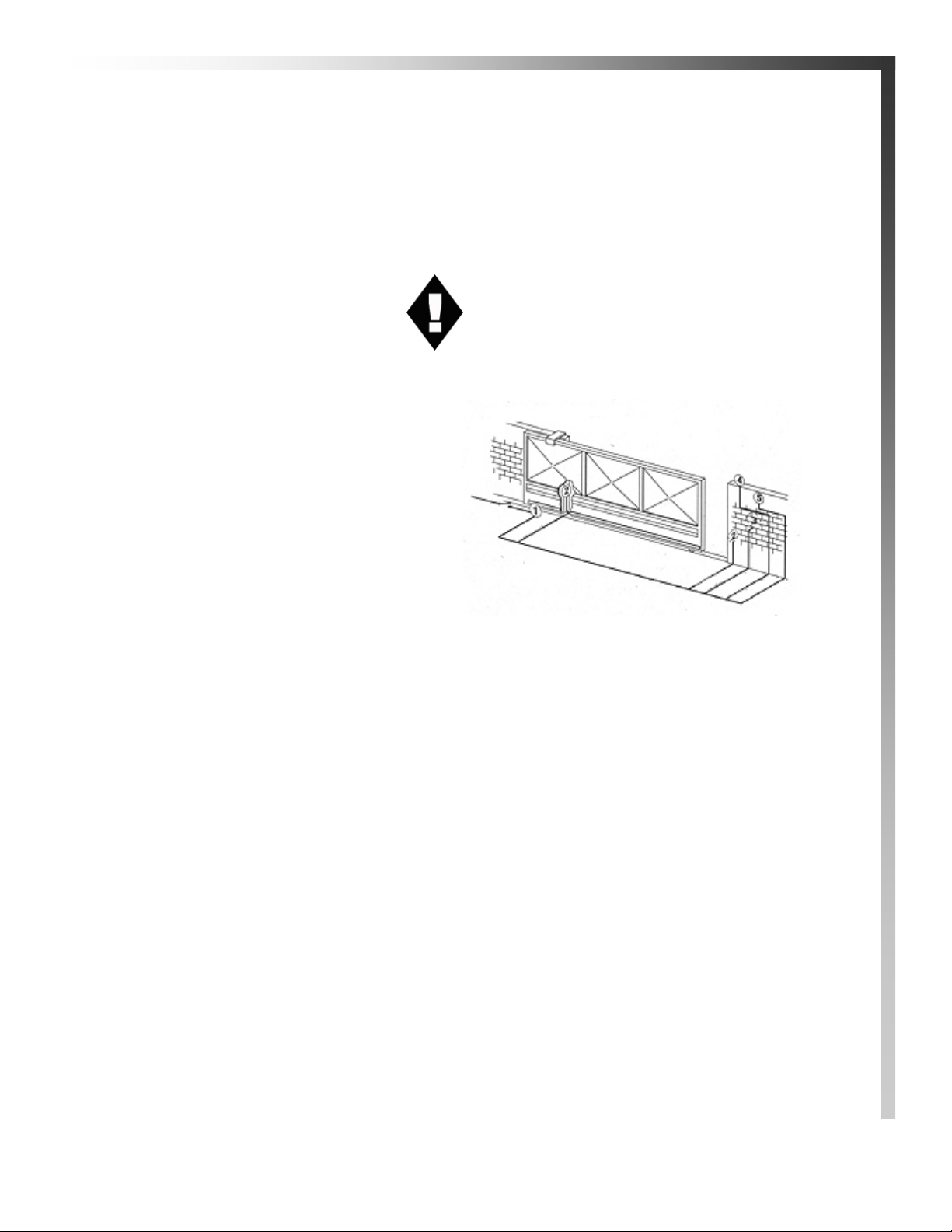
Standard System
Overview and Safety
Zones
The system display to the right is a
recommended standard system. Oth-
er approved accessories can be in-
stalled. Photo sensors and a flashing
light indicating gate movement is
recommended for safety purposes.
1 Estate Swing Operator
2 Photocells (not included)
3 Key operated pushbutton (not included)
4 Flashing lamp (not included)
5 Radio receiver (optional)
Notes: 1) Do not extend operator connection cables
2) When laying electrical cables, use
appropriate rigid and/or flexible tube
3) Do not run any wires in the same conduit as
110 AC power that may be in the area. This
will cause unwanted interference

Tools Needed
Power Drill
Crescent Wrench
Metal Drill Bits
Hacksaw
Flat Head Screwdriver
Phillips Head Screwdriver
Tape Measure
Level
Wire Strippers
C-clamps
Other items that may be needed prior to commencing installation.
Cement, boards for a slab frame, and a trowel.
Low voltage wire will be required to run power to your operator. See the power
page for specifications.
If the gate is more than 144’ from an a/c power supply then an electrician will be
required to move a supply closer.
Depending on the current base, you may need cement to form a level mounting
pad.
A voltage meter may be necessary to run diagnostic checks.
A digital camera will come in handy with technicians if any support is needed.
3

4
Manual Operation
1. Key release the lever.
2. Lift the lever to disengage the gears.
3. The motor will not run again until the motor is relocked There is a magnetic sen-
sor that allows the motor to operate, be sure the magnet is lined up with the sen-
sor..
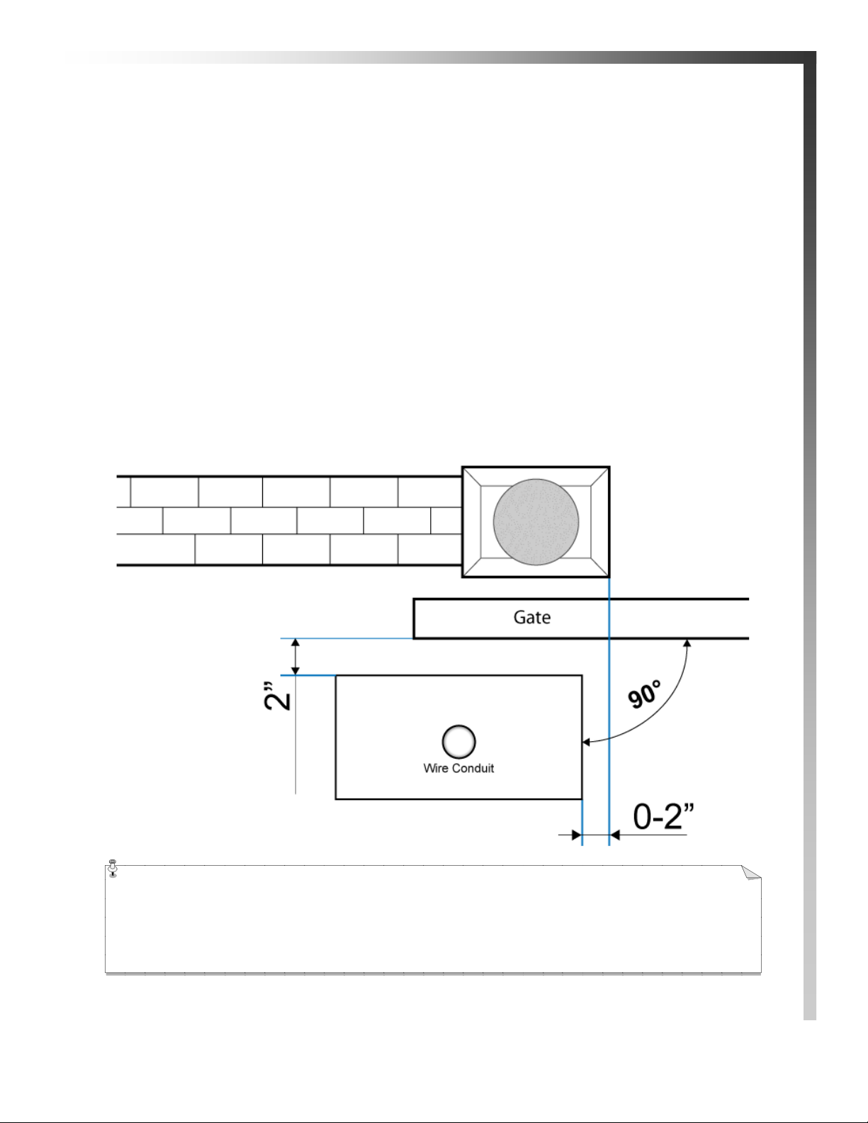
Creating a Mounting Slab
5
1. Determine the height of your concrete pad based upon how high the gate is from the ground
and where the rack will be mounted to the gate. The minimum distance from the bottom of the
rack to the ground is 4”.
2. Pour a concrete pad for your opener to bolt to. Levelness of the pad is important. For conven-
ience place a piece of conduit that runs up the center of the pad and the other end is easily ac-
cessible.
3. After the foundation has dried, use 7/16 concrete anchors attach the opener to the base.
NOTE: The gate opener can be placed on the left or r ight of the dr iveway, The diagr am
below is for being placed on the left side of the driveway (if you are standing on the inside of
the property looking out)
Concrete Slab Tips: Creating a wood rectangle with no top is a good way to form a
slab. After the cement dries the wood can be knocked away. The slab must be secured to
the ground below. Having rebar pass into the slab works well.
If the height of the operator from the slab ever has to be adjusted, nuts can be inserted just on the threads
between the anchor and the bottom of the opener—the opener can be moved up the threading and the op-
erator can rest on the nuts.
Feed any wires up through the opener while installing the opener to the base.
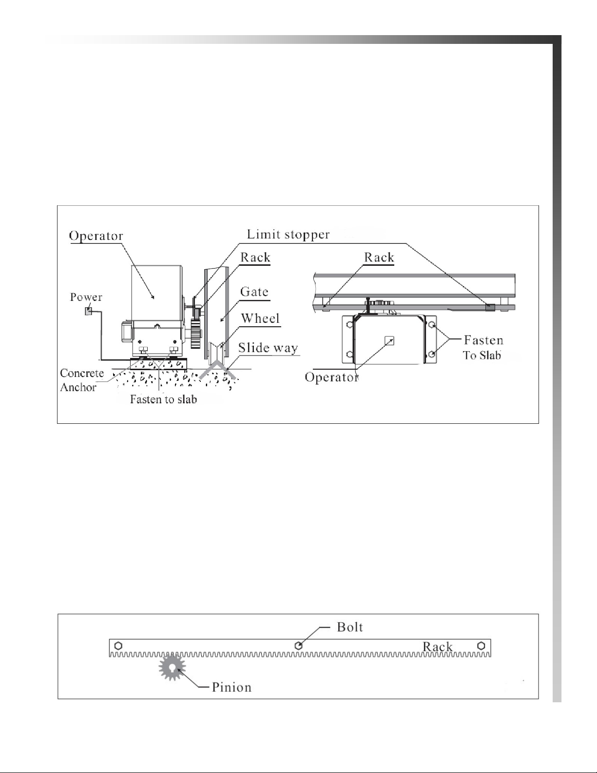
1. Manually take the leaf to its close position.
2. Lay the first piece of rack at the appropriate level and mark the hole position on the gate. Make a hole
and use nuts, bolts and washers to make a connection to the gate (not provided).
The holes in the rack are made oblong for adjustment after the holes are drilled. No special bolts are re-
quired for mounting, simply tightening the bolts will hold the rack secure.
6
Rack Installation
Securing the Operator

7
3. Move the gate manually, checking if the rack is resting on the pinion. Repeat at each hole.
4. Bring another rack element near the previous one, using a piece of rack (as shown below) to
synchronize the teeth of the two elements.
5. Move the gate manually and carry out the securing operations as far as the first element, pro-
ceeding until the gate is fully covered.
Notes on rack installation
Make sure that during the gate travel, all the rack elements mesh correctly with the pinion.
Do not, on any account, weld the rack elements either to the spacers or to each other.
When you have finished installing the rack, adjust the distance between the pinion teeth and
the rack groove. Check if the distance is .06” (below) along the entire travel using the rack
slots.
Manually check if the gate habitually reaches the travel limit mechanical stops and make sure
that there is no friction during gate travel.
Do not use grease or other lubricants between rack and pinion.

8
Auto Reclose, Left/Right Mode, Force
The gate can be set to automatically reclose after a certain period of time or work like a garage door
opener; where it goes open and stays open until you press your remote to reclose it (OFF).
If auto reclose is on from the chart above adjust the time on the potentiometer (seen below)
Clockwise is a longer pause time.
The force of the motor is adjustable - Lowest means it will obstruct easier, highest means it will exert more force on an
object before obstructing.
Motor Side: Left indicates the motor is mounted on the left hand side of the driveway, right is if the motor is on the
right side of the driveway.
The side is determined if you are standing on the outside of the property looking in facing the opener.
Dip switches and auto-reclose time must be set with both transformer and
battery power off to take effect.

9
Power Connection
1. The provided 24V DC battery is for back up, connect it to the pre-wired connector on the board
before plugging in your transformer.
2. The Estate Swing E-SL 450 comes with 1) 24V transformer. The transformer supplied has 2 yel-
low wires to be spliced to low voltage wire . You may extend those wires and locate the trans-
former up to 400’ away from the control board using 2 conductor stranded 16 gauge direct
burial wire. The transformer must be kept in a weather pr otected ar ea and also in a
location that it cannot be tampered with by children or pets. It is be.
3. Connect the two wires form the transformer on the top and bottom screw terminals on the white
connector on the side of the gate opener.
4. Plug the transformer into a 120 VAC outlet.
Never run 110VAC power directly to the Estate Swing. This will destroy the Estate Swing
control board. Never connect the power wire with the transformer plugged in. Contact
between the two lead wires, even for a second, will destroy the transformer.
Transformers are only warranted if the internal fuse is not blown. If the fuse is blown an outside factor
(shorting, surge, water, etc) has caused the transformer not to function.

10
Temporary Safety Jumpers
For the highest level of safety, the Estate Swing systems are set up with Normally Closed safety
terminals. This means that in order for the gate opener to move these terminals must be closed
either through a safety device (recommended) or with jumpers. Temporary safety jumpers are in-
stalled in the factory
It is recommended not to use any accessories until setup and programming is complete.
NOTE: If not using safety devices the temporary safety jumper must remain in. In order for
the gate operator to move. Also in order for safety devices to function the safety jumpers
must be removed.
Troubleshooting tip:
If the gate will only open and will not close - the safety jumper is not making a connection
between the two terminals. Even with a jumper in place, sometimes metal or wire loses its
conductivity for various reasons. Please try to replace this jumper and see if the problem is
resolved.
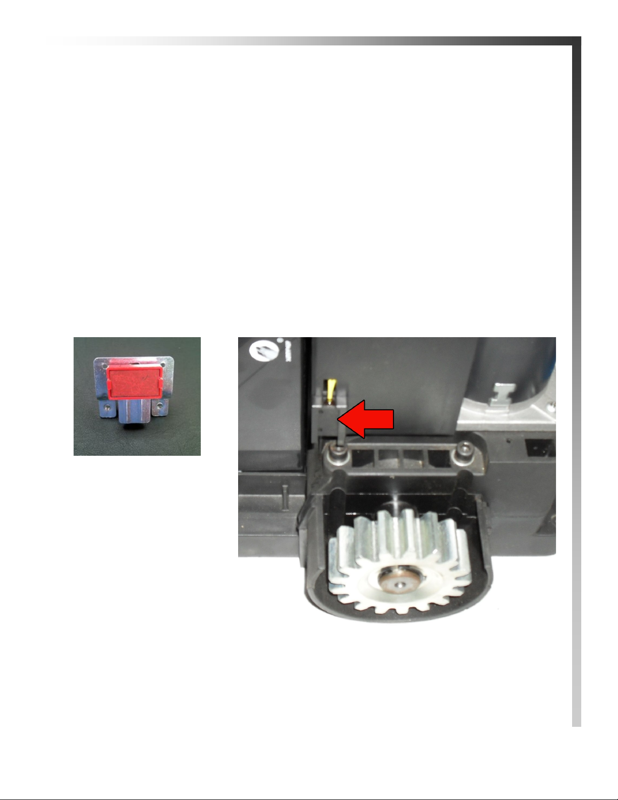
The ESTATE SLIDE operator is supplied with a magnetic limit switch and bracket to be secured
to the top of the rack, this commands gate movement to stop in the open position.
1. Move the gate to the open position.
2. Attach the plate, as shown below (A), to the rack.
3. Be sure it is lined up with the magnet, as shown below (B), on the side of the operator. The
red limit light should come on when the magnet is lined up.
4. After the magnet is lined up, move the gate open for programming.
The open stop point will be learned by programming later in the manual
Travel Limit Installation for OPEN position
(A)
Red part is magnet, face
toward the operator.
Sliver part is attached to
top of rack.
(B)
This is the limit detector, this should line up with the red
magnet (A) in the OPEN position.
11
12
Note: If your gate moves further closed instead of open: the motor side is incorrect.
Remove battery and transformer power.
Change dip switch number 3 to the opposite position it is currently on.
Reapply power and begin programming again.
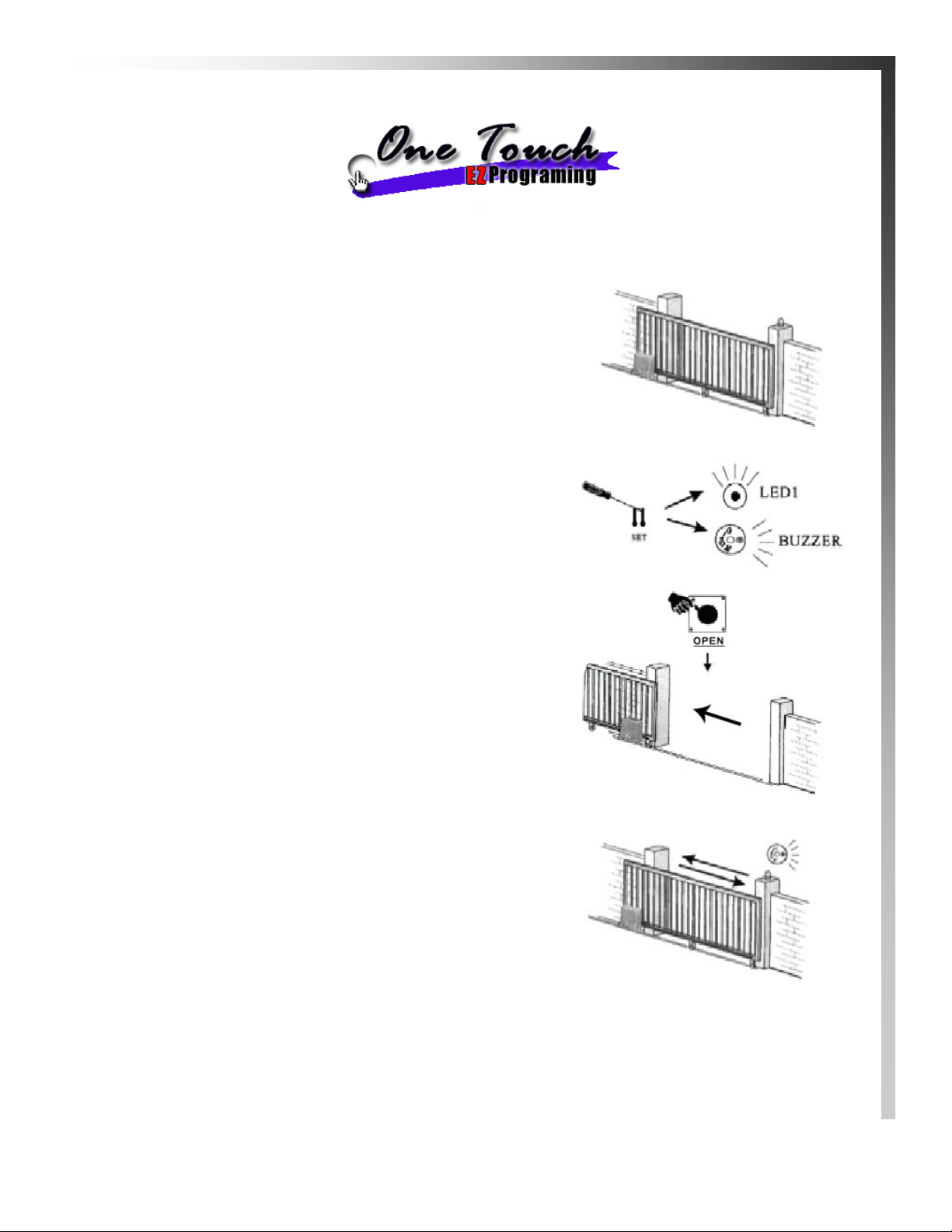
In this stage, your control board will memorize run time and where to stop in the open position.
Manually release and close the gate; then lock it into
gear. This position should be where you want the gate to
stop every time.
Using a screwdriver jump the pins on the lower right of
the board marked SET. LED1 will flash and the buzzer
will beep 3 times.
Press the OPEN button. The gate will go open and stop
on the limit magnet.
The gate will then move closed, stopping in the original
closed position and then go back open again as a test
cycle. Programming is now done.

Receiver
The receiver is built into the board. It can have up to 6 remotes programmed into the
system. It has two types of openings that can be programmed in - Full Open/Close and
Pedestrian Open. Full opening is normal operation of the gate. Pedestrian opening will
partially open the gate and stop. The gate can then be closed again by using the full open/
close.
Warning: gate opener may run immediately when programming is finished - do not
program transmitters before programming run time.
Programming Full Open / Close Button:
1. Choose a button on the remote.
2. Press the LEARN button and the LEARN LED will light up.
3. Press and hold the button you have chosen for Full Open / Close on a remote until the
LEARN LED light goes out.
4. Repeat with other remotes.
Programming Pedestrian Open Button:
1. Choose a button on the remote.
2. Press the LEARN button TWICE and the LEARN LED will flash twice and then light
up.
3. Press and hold the button you have chosen for Full Open / Close on a remote until the
LEARN LED light goes out.
4. Repeat with other remotes.
Erasing All Transmitters: Press hold LEARN button until the LEARN LED flashes.
You will then have to reprogram all remotes back in.
13
Setting Transmitters

Control Board Overview
Caution! Do not run 120V AC power dir ect to the board. This will cause per manent damage to
both boards and void your warrantee. Caution!
From left to right
Hall: Counter that memor izes the open position of the gate.
FUSE: Check if gate comes in contact with obstacle during motion or after electr ical surge.
MOTOR. The motor gets wired into this terminal. It is a DC motor and comes pr ewired.
BATTERY: 24VDC - Battery provided with connector.
LIGHT: This would power a 24VDC light during the motion of the gate.
TRAN: NOT USED IN THIS APPLICATION
PUSH/GND. Between the push and gr ound terminal you would put any entry or exit accessory
input. This would be keypads, push buttons, etc. It is a normally open circuit and when the circuit is
closed momentarily it makes the gate go into motion.
The receiver is prewired in these terminals but more devices can be added in parallel.
OPEN/CLOSE/GND: OPEN and GRD is used for nor mally open devices you would like to only
open the gate from the closed position.
CLOSE and GND is used for normally open devices you would like to only close the gate from the
open position.
CONTINUED ON NEXT PAGE
14

Control Board Overview
Caution! Do not run 120V AC power dir ect to the board. This will cause per manent damage to
both boards and void your warrantee. Caution!
Continued:
LIMIT/LH: Pr ewired - this is where the limit switch and clutch switch are wired. Do not move.
GND/PHOTO: Photo with the gr ound would be for safety device inputs like a loop or photo
eye. It is a normally closed and when the circuit is broken the gate opener stops. If a safety device is
not being used in this terminal the operator must have a jumper ran from this terminal to the
GND terminal in order to operate.
Note: GDN has the negative power for the receiver pre-wired into it. You can add more wires in
parallel.
V+: This is a very low 12VDC output only to be used with a photo cell - not for other accessories.
+24V: This ter minal puts out a constant 24V DC cur r ent for the r eceiver.
PUSH BUTTON: Opens and Closes the gate.
OPEN BUTTON: Opens the gate fr om the closed position.
CLOSED BUTTON: Used for pr ogr amming and testing.
LEARN BUTTON: Used for pr ogr amming r emotes.
15

16
The manufacturer instructions that come with your accessory should have markings for
wires or terminals to connect to the gate opener. Please look for terminals named below in
the instructions for the accessory.
Keypads, Receivers:
Normally Open (NO) or Input (INP) or Relay of entry device = PUSH terminal on gate
opener control board.
Common (COM) or Ground (GND) or Relay of entry device = GND terminal on gate open-
er control board.
NOTE: If the power for the accessory shares a Ground wire/terminal with the relay – Do Not
power that accessory off this control board (example: WKP-P keypad). Instead power that de-
vice with batteries.
24V Power positive (+) or (24V) or (PWR) of entry device = +24V terminal of gate opener
control board.
24V Power Negative (-) or (GND) or (PWR) of entry device = GND terminal of gate opener
control board.
Push Button, Intercoms:
Normally Open (NO) or Input (INP) or Relay of entry device = PUSH terminal of gate
opener control board.
Common (COM) or Ground (GND) or Relay of entry device = GND terminal of gate open-
er control board.
Push buttons do not require power and Intercoms draw too much power to power from
the gate opener.
Exit Wand/Sensor, Exit Loop Detector, Exit Device:
Normally Open (NO) or Input (INP) or Relay of exit device = OPEN terminal of gate open-
er control board.
Common (COM) or Ground (GND) or Relay of exit device = GND terminal of gate opener
control board.
24V Power positive (+) or (24V) or (PWR) of exit device = +24V terminal of gate opener
control board.
24V Power Negative (-) or (GND) or (PWR) or Shield wire of exit device = GND terminal
of gate opener control board.
Accessories Wiring

17
Photo Eye, Safety Edge, Safety Loop:
Normally Closed (NC) of safety device = Photo terminal of gate opener control board.
Common (COM) or Ground (GND) of safety device = GND terminal of gate opener control
board.
24V Power positive (+) or (24V) or (PWR) of safety device = V+ terminal of gate opener
control board.
24V Power Negative (-) or (GND) or (PWR) of safety device = GND terminal of gate opener
control board.
*Remove safety jumper from PHOTO terminal if using a safety device.
Magnetic Gate Lock: Magnetic gate locks must have their own power supply and
their own relay.
Coil of relay for magnetic lock = L1-1 Motor lead terminal of gate opener control board.
Coil of relay for magnetic lock = L1-2 Motor lead terminal of gate opener control board.
Connect positive lead of the power supply directly to the positive lead of the mag lock.
Connect negative lead of the power supply to the N/C terminal of the relay.
Connect the COM terminal of the relay to the negative lead of the mag lock.
Accessories Wiring

18
If you call in for technical support or warranty
support: before any control board or motor will be
permitted to be sent in for testing or warranty you will be
required to e-mail digital photos to the technician.
This is done in your best interest to save unnecessary shipping expenses and time lost. Many times
we can come up with solutions to issues by seeing pictures that relay information that is impossible
to relay through a phone conversation.
Below is an example of a control board picture that we will be looking for:
Warranty / Troubleshooting Notice
Other manuals for E-SL 450 Series
1
Table of contents
Other Estate Slide Gate Opener manuals


