Estate Slide E-SL 450BD Series User manual

—WARNING—
Read all instrucons before beginning installaon or use of
this gate opener. This operator exerts a high level of force.
Exercise cauon at all mes and stay clear of the system
during operaon.
INSTRUCTION MANUAL
USER DRIVEN MANUAL*
Any feedback, changes, or advice we are
glad to hear it. Please contact us at
E-SL 450BD Series
*Estate Swing’s unique user driven manuals are constantly updated by installers and homeowners like yourself. We improve by hearing and applying your
feedback.

E-SL 450BD Series Instrucon Manual
Estate Swing Summary of Functions
Estate Slide Summary of Funcons
The Estate Slide is only to be used for vehicular Slide gates in a Class I seng.
Class I: A vehicular gate opener (or system) intended for use in a home of one-to-four single family
dwelling, or a garage or parking area associated therewith.
The Estate Slide automated system was designed and built for controlling vehicle access. Do not use
for any other purpose.
The Estate Slide automated system automates residenal Slide-leaf gates with leaves of up to 18’ in
length.
It consists of a locking electro-mechanical linear operator, powered by a 24V AC transformer, coupled
with control board that switches the voltage to DC to power the motor. The MASTER card can be pro-
grammed and is used to set the following: funcon logics, work mes (by self-learning) and pause
mes, leaf speed, and the sensivity of the an-crushing device.
The locking system will automacally lock when the motor is not operang. A release system enables
the gate to be moved by hand in case of a system failure.
For Your Assistance
Keep this manual safely stored aer installaon
Serial Number ________________________________
Date of Purchase _____________________________
Place of Purchase ____________________________
Have this informaon on hand while handling all service and warranty issues.

E-SL 450BD Series Instrucon Manual
Specifications & Part List
1
Model Estate Slide 450BD
Power Supply 24 V AC / 24V DC
Absorbed Power (W) 50
Absorbed Current (Amps) 10
Max Run Time 5.6 Minutes
Operang Ambient Temperature -4 °F to +124 °F
Motor Rotaonal Speed 2000r / min
Gate Leaf Max Length (.) Up to 14
Gate Leaf Max Weight (lbs.) Up to 450
Type of Limit Switch Magnec
Estate Swing Parts Included:
A) Two Remotes
B) Transformer
C) Limit Magnet
D) Release Keys
E) Baery
F) Belt
G) Motor

E-SL 450BD Series Instrucon Manual
Standard System Overview and Safety Zones
The system display below is a recommended standard system. Other approved accessories can be in-
stalled.
Photo sensors and a ashing light indicang gate movement is recommended for safety purposes.
1) Estate Slide Operator 2) Photocells (not included) 3) Key operated pushbuon (not included) 4)
Flashing lamp (not included) 5) Radio receiver (oponal)
NOTES:
1) Do not extend operator connecon cables
2) When laying electrical cables, use appropriate rigid and/or exible tube
3) Do not run any wires in the same conduit as 110 AC power that may be in the area.
This will cause unwanted interference
Important Preliminary Checks:
To ensure safety and an eciently operang automated system, make sure the following condi-
ons are observed.
• The gate and post must be suitable for being automated. Check that the structure is suciently
strong and rigid, and its dimensions and weights conform to those indicated in secon 1. In parcu-
lar, wheel diameter must be in relaon to the weight of the gate to be automated. Dimensions and
weight must match those indicated in the technical specicaons.
• Make sure the leaves move smoothly without any irregular fricon during enre travel.
• The soil must permit sucient stability for the expansion plugs securing the foundaon plate.
• Check if the upper guide and travel limit mechanical stops are installed.
We advise you to have any metalwork carried out before the automated system is installed.
2

E-SL 450BD Series Instrucon Manual
Tools Needed For Installation
3
• Power Drill
• Crescent Wrench
• Metal Drill Bits
• Hacksaw
• Flat Head Screwdriver
• Phillips Head Screwdriver
• Tape Measure
• Level
• Wire Strippers
• C-clamps
Other items that may be needed prior to commencing installaon:
• Cement, boards for a slab frame, and a trowel.
• Low voltage wire will be required to run power to your operator. See the power page for
specicaons.
• If the gate is more than 144’ from an a/c power supply then an electrician will be required
to move a supply closer.
• Depending on the current base, you may need cement to form a level mounng pad.
• A voltage meter may be necessary to run diagnosc checks.
• A digital camera will come in handy with technicians if any support is needed.

E-SL 450BD Series Instrucon Manual
Manual Operation
4
1. Key release the lever.
2. Li the lever to disengage the gears.
3. The motor will not run again unl the motor is relocked. There is a magnec sensor that allows
the motor to operate, be sure the magnet is lined up with the sensor.

E-SL 450BD Series Instrucon Manual
Creating Mounting Slab
5
1. Determine the height of your concrete pad based upon how high the gate is from the ground and where the
belt can be mounted to the gate. The minimum height from the top of the slab to the belt is 10”.
2. Pour a concrete pad for your opener to bolt to. Levelness of the pad is important. For convenience place a
piece of conduit that runs up the center of the pad and the other end is easily accessible.
3. Aer the foundaon has dried, use 7/16 concrete anchors aach the opener to the base.
NOTE: The gate opener can be placed on the le or right of the driveway. The diagram below is for being
placed on the le side of the driveway (if you are standing on the inside of the property looking out)
Mount Base
* Pad can be larger/closer to gate as long as opener is mounted at correct distance from the gate.
** Dimension can be greater if spacers are used to oset gate brackets from rear face of gate.
Spacers will need to be (Base distance from gate) - 31/8 = Spacer Width.
Concrete Slab Tips: Creang a wood rectangle with no top is a good way to form a slab. Aer the cement
dries the wood can be knocked away. The slab must be secured to the ground below. Having rebar pass into
the slab works well.

E-SL 450BD Series Instrucon Manual
Securing the Operator
6
If the height of the operator from the slab ever has to be adjusted, nuts can be inserted just on the
threads between the anchor and the boom of the opener—the opener can be moved up the
threading and the operator can rest on the nuts.
Feed any wires up through the opener while installing the opener to the base.

E-SL 450BD Series Instrucon Manual
Installation of Motor
7
Horizontal posion of gate bracket: The hole in the gate brack-
et should be mounted on the gate so it is centered with the
idler gears horizontally. Depending on how close you mounted
the gate opener from the rear face of the gate you may need to
shim your bracket to make it protrude o the back of the gate
more to achieve this.
Vercal posion of gate bracket: The hole in the gate bracket
should be level with the top of the idler gears when mounted
on the gate.
Aer idenfying the correct height for the gate bracket, bolt
the bracket to your gate frame using the three mounng holes.
The at side with a single hole should be facing in toward the
center of the gate.
On one side of the gate lay the belt into the belt aachment
bracket so the teeth of the belt mesh the teeth of the bracket.

E-SL 450BD Series Instrucon Manual
Installation of Motor
8
Lay the top of the belt bracket on the belt. It has two holes
in it. Mark and drill two holes in the belt . Then put the
bolts through the bolt bracket assembly to hold the brack-
et to the belt.
Aach the assembled belt bracket to the belt
aachment bolt.
Run the belt over the idlers and under the mechanized
gear with the belt teeth facing up.
Repeat gate bracket and belt bracket steps on the other
side of the gate to aach the other end of the belt to the
gate. The belt may need to be cut down to be ght if you
gate is not 15 feet long including tail. Do not cut the belt
unl you have run the belt through the gears to account
for the length needed for this.
Make your nal ghtening adjustments on the belt. The
belt should not have excessive sag in it (no more than 2
inch variance from furthest bracket to opener). To ghten
the belt aer mounng, move the nuts on the belt aach-
ment bolt.

E-SL 450BD Series Instrucon Manual
Installation of Motor
9
Find the correct height for the limit magnet to nd
the mounng spot from the gate. This should be done
in conjuncon with the next step of adjusng the hor-
izontal distance the limit switch protrudes from the
side of the unit. The distance from the limit magnet
to the limit switch should be under 1 inch.
Adjust the limit switch horizontally to match up with
the limit magnet. The distance between the two
should not exceed 1 inch.
Mount your limit magnet on the provided piece of at
bar. The at bar is intended to be aached to your
gate at the correct height to trigger your limit switch
in the gate’s OPEN posion. There are many ways to
aach the at bar to your gate so the bar is le un-
drilled and unpainted for best suing it to your style
gate.
Example: In the photo the gate is picket style, in this
case we would use self tapping metal screws to
aach the bar to the pickets. Then we would paint
the at bar black.

E-SL 450BD Series Instrucon Manual
Auto Reclose, Left / Right Mode, Force
10
Dip switches and auto-reclose me must be set with both transformer and baery power o
to take eect.
The force of the motor is adjustable - Lowest means it will obstruct easier, highest means it will
exert more force on an object before obstrucng.
Motor Side: Le indicates the motor is mounted on the le hand side of the driveway, right is
if the motor is on the right side of the driveway.
The side is determined if you are standing on the outside of the property looking in facing the
opener.
The gate can be set to automacally reclose aer a certain period of me or work like a garage
door opener; where it goes open and stays open unl you press your remote to reclose it (OFF).
If auto reclose is on from the chart above adjust the me on the potenometer (seen below)
Clockwise is a longer pause me.

E-SL 450BD Series Instrucon Manual
DIY Power Connection
11
1. The provided 24V DC baery is for back up, connect it to the pre-wired connector on the board be-
fore plugging in your transformer.
2. The Estate Swing E-SL 450BD comes with 1) 24V transformer. The transformer supplied has 2 yellow
wires to be spliced to low voltage wire . You may extend those wires and locate the transformer up
to 400’ away from the control board using 2 conductor stranded 16 gauge direct burial wire. The
transformer must be kept in a weather protected area and also in a
locaon that it cannot be tampered with by children or pets. It is be.
3. Connect the two wires form the transformer on the top and boom screw terminals on the white
connector on the side of the gate opener.
4. Plug the transformer into a 120 VAC outlet.
Never run 110VAC power directly to the Estate Swing. This will destroy the Es-
tate Swing control board. Never connect the power wire with the transformer
plugged in. Contact between the two lead wires, even for a second, will destroy
the transformer.
Transformers are only warranted if the internal fuse is not blown. If the fuse is blown an outside factor (shorng, surge, water, etc)
has caused the transformer not to funcon.
E-SL 450BD Series Instrucon Manual
Temporary Safety Jumpers
12
For the highest level of safety, the Estate Swing systems are set up with Normally Closed safety ter-
minals. This means that in order for the gate opener to move these terminals must be closed either
through a safety device (recommended) or with jumpers. Temporary safety jumpers are installed in
the factory
It is recommended not to use any accessories unl setup and programming is complete.
NOTE: If not using safety devices the temporary safety jumper must remain in. In order for the
gate operator to move. Also in order for safety devices to funcon the safety jumpers must be re-
moved.
Troubleshoong Tip:
If the gate will only open and will not close - the safety jumper is not making a con-
necon between the two terminals. Even with a jumper in place, somemes metal
or wire loses its conducvity for various reasons. Please try to replace this jumper
and see if the problem is resolved.

E-SL 450BD Series Instrucon Manual
Learning Closed Position
13
In this stage, your control board will memorize run me and where to stop in the
closed posion.
Manually release and close the gate; then lock it into gear.
This posion should be where you want the gate to stop
every me.
Using a screwdriver jump the pins on the lower right of
the board marked SET. LED1 will ash and the buzzer will
beep 3 mes.
Press the OPEN buon. The gate will go open and stop on
the limit magnet.
The gate will then move closed, stopping in the original
closed posion and then go back open again as a test
cycle. Programming is now done.
Note: If your gate moves further closed instead of open:
the motor side is incorrect.
• Remove baery and transformer power.
• Change dip switch number 3 to the opposite posion it is currently on.
• Reapply power and begin programming again.

E-SL 450BD Series Instrucon Manual
Setting Transmitters
14
Receiver
The receiver is built into the board. It can have up to 6 remotes programmed into the system. It has two types of
openings that can be programmed in - Full Open/Close and Pedestrian Open. Full opening is normal operaon of
the gate. Pedestrian opening will parally open the gate and stop. The gate can then be closed again by using the
full open/close.
Warning: gate opener may run immediately when programming is nished - do not program transmiers be-
fore programming run me.
Programming Full Open / Close Buon:
1. Choose a buon on the remote.
2. Press the LEARN buon and the LEARN LED will light up.
3. Press and hold the buon you have chosen for Full Open / Close on a remote unl the LEARN LED light goes
out.
4. Repeat with other remotes.
Programming Pedestrian Open Buon:
1. Choose a buon on the remote.
2. Press the LEARN buon TWICE and the LEARN LED will ash twice and then light up.
3. Press and hold the buon you have chosen for Full Open / Close on a remote unl the LEARN LED light goes
out.
4. Repeat with other remotes.
Erasing All Transmiers: Press and hold LEARN buon unl the LEARN LED ashes. You will then have to repro-
gram all remotes back in.

E-SL 450BD Series Instrucon Manual
Control Board Overview
15
Cauon! Do not run 120V AC power direct to the board. This will cause permanent damage to
both boards and void your warranty. Cauon!
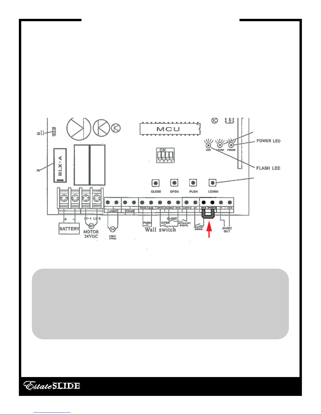
From Le to Right
• Hall: Counter that memorizes the open posion of the gate.
• FUSE: Check if gate comes in contact with obstacle during moon or aer electrical surge.
• MOTOR: The motor gets wired into this terminal. It is a DC motor and comes prewired.
• BATTERY: 24VDC - Baery provided with connector.
• LIGHT: This would power a 24VDC light during the moon of the gate.
• TRAN: NOT USED IN THIS APPLICATION.
• PUSH/GND: Between the push and ground terminal you would put any entry or exit accessory input. This
would be keypads, push buons, etc. It is a normally open circuit and when the circuit is closed momentarily it
makes the gate go into moon. The receiver is prewired in these terminals but more devices can be added in
parallel.
• OPEN/CLOSE/GND: OPEN and GRD is used for normally open devices you would like to only open the gate
from the closed posion. CLOSE and GND is used for normally open devices you would like to only close the
gate from the open posion.
Connue on next Page

E-SL 450BD Series Instrucon Manual
Control Board Overview
16
Cauon! Do not run 120V AC power direct to the board. This will cause permanent damage to
both boards and void your warranty. Cauon!
Connued:
• LIMIT/LH: Prewired - this is where the limit switch and clutch switch are wired. Do not move.
• GND/PHOTO: Photo with the ground would be for safety device inputs like a loop or photo eye. It is a nor-
mally closed and when the circuit is broken the gate opener stops. If a safety device is not being used in this
terminal the operator must have a jumper ran from this terminal to the GND terminal in order to operate.
Note: GDN has the negave power for the receiver pre-wired into it. You can add more wires in parallel.
• V+: This is a very low 12VDC output only to be used with a photo cell - not for other accessories.
• +24V: This terminal puts out a constant 24V DC current for the receiver.
• PUSH BUTTON: Opens and Closes the gate.
• OPEN BUTTON: Opens the gate from the closed posion.
• CLOSED BUTTON: Used for programming and tesng.
• LEARN BUTTON: Used for programming remotes.

E-SL 450BD Series Instrucon Manual
Warranty / Troubleshooting Notice
17
If you call in for technical support or warranty
support: before any control board or motor will be
permied to be sent in for tesng or warranty you
will be required to e-mail digital photos to the
technician.
This is done in your best interest to save unnecessary shipping expenses and me lost. Many
mes we can come up with soluons to issues by seeing pictures that relay informaon that is
impossible to relay through a phone conversaon.
Below is an example of a control board picture that we will be looking for:

E-SL 450BD Series Instrucon Manual
Accessories Wiring
18
The manufacturer instrucons that come with your accessory should have markings for wires or ter-
minals to connect to the gate opener. Please look for terminals named below in the instrucons for
the accessory.
Keypads, Receivers:
Normally Open (NO) or Input (INP) or Relay of entry device = PUSH terminal on gate opener control
board.
Common (COM) or Ground (GND) or Relay of entry device = GND terminal on gate opener control
board.
NOTE: If the power for the accessory shares a Ground wire/terminal with the relay – Do Not power that
accessory o this control board (example: WKP-P keypad). Instead power that device with baeries.
24V Power posive (+) or (24V) or (PWR) of entry device = +24V terminal of gate opener control board.
24V Power Negave (-) or (GND) or (PWR) of entry device = GND terminal of gate opener control
board.
Push Buon, Intercoms:
Normally Open (NO) or Input (INP) or Relay of entry device = PUSH terminal of gate opener control
board.
Common (COM) or Ground (GND) or Relay of entry device = GND terminal of gate opener control
board.
Push buons do not require power and Intercoms draw too much power to power from the gate
opener.
Exit Wand/Sensor, Exit Loop Detector, Exit Device:
Normally Open (NO) or Input (INP) or Relay of exit device = OPEN terminal of gate opener control
board.
Common (COM) or Ground (GND) or Relay of exit device = GND terminal of gate opener control board.
24V Power posive (+) or (24V) or (PWR) of exit device = +24V terminal of gate opener control board.
24V Power Negave (-) or (GND) or (PWR) or Shield wire of exit device = GND terminal of gate opener
control board.
Other manuals for E-SL 450BD Series
1
Table of contents
Other Estate Slide Gate Opener manuals


