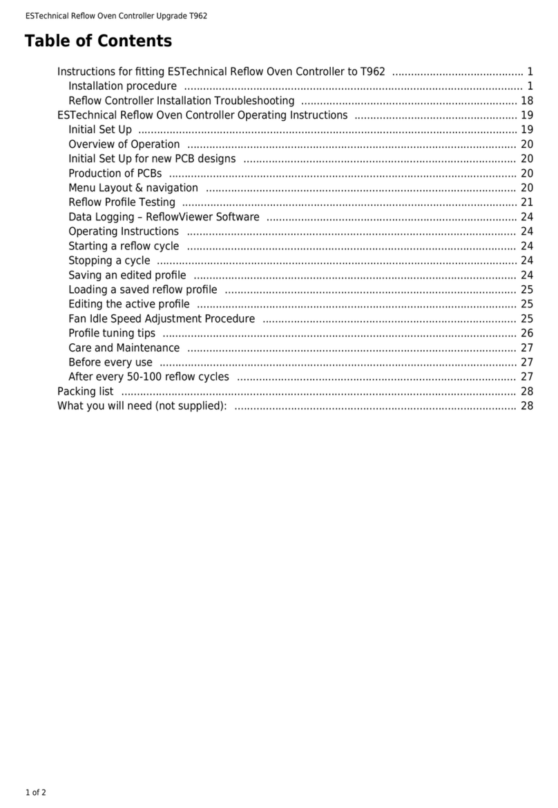
ESTechnical Reflow Oven Controller User manual

ESTechnical Reflow Oven Controller Full Upgrade Kit for T962A
1 of 2
Table of Contents
Instructions for fitting ESTechnical Reflow Oven Controller Full Upgrade Kit to T962A 1 .............
Installation procedure 1 ............................................................................................................
Reflow Controller Installation Troubleshooting 39 .....................................................................
ESTechnical Reflow Oven Controller Operating Instructions 40 ....................................................
Initial Set Up 40 .........................................................................................................................
Overview of Operation 40 .........................................................................................................
Initial Set Up for new PCB designs 40 .......................................................................................
Production of PCBs 41 ...............................................................................................................
Menu Layout & navigation 41 ...................................................................................................
Reflow Profile Testing 41 ...........................................................................................................
Data Logging – ReflowViewer Software 44 ................................................................................
Operating Instructions 45 .........................................................................................................
Starting a reflow cycle 45 .........................................................................................................
Stopping a cycle 45 ...................................................................................................................
Saving an edited profile 45 .......................................................................................................
Loading a saved reflow profile 45 .............................................................................................
Editing the active profile 45 ......................................................................................................
Fan Idle Speed Adjustment Procedure 45 .................................................................................
Profile tuning tips 46 .................................................................................................................
Care and Maintenance 48 .........................................................................................................
Before every use 48 ..................................................................................................................
After every 50-100 reflow cycles 48 .........................................................................................
Packing list 48 ..............................................................................................................................
What you will need (not supplied): 49 ..........................................................................................

ESTechnical Reflow Oven Controller Full Upgrade Kit for T962A
2 of 2

ESTechnical Reflow Oven Controller Full Upgrade Kit for T962A
1 of 50
ESTechnical Reflow Oven Controller Full Upgrade Kit for
T962A
Reflow Controller hardware
www.estechnical.co.uk
Thank you for your purchase of ESTechnical products. If you have any questions or comments please
let us know, we are always keen to hear feedback about our products.
Instructions for fitting ESTechnical Reflow Oven Controller Full Upgrade Kit to T962A
Packing List
What you will need (not supplied)
Installation procedure
Warning
IMPORTANT – mains electrical wiring is involved in the
installation of this controller, but no mains voltages are
connected directly to the controller. If you are in any doubt
please consult a qualified electrician.
Auto Reset Jumper
The ESTechnical reflow controller v4 PCB and onwards has a jumper
for enabling or disabling the auto-reset behaviour of the MCU. With
the jumper connecting the two pins it is possible to easily upload new
firmware to the controller via USB to serial connection from a
computer. With the jumper open, the MCU will not automatically
reset when the serial port is opened by a computer - this is more
convenient in normal operation and we suggest that you operate the
controller with the jumper open.

ESTechnical Reflow Oven Controller Full Upgrade Kit for T962A
2 of 50
Unplug the power cable from the reflow oven.1.
Remove the drawer from the unit (pull forwards until it stops, then carefully undo the clips2.
(gently move the plastic levers) that keep the drawer in the runners, then slide the drawer out
from the runners. Set the drawer aside.
Drawer runner clip
Remove the screws that are under the front edge of the lid, there are two or three screws in the3.
drawer opening, keep these safe.

ESTechnical Reflow Oven Controller Full Upgrade Kit for T962A
3 of 50
Front screws
Turn the unit around so you are looking at the back, remove the screws that hold the lid on the4.
case, keep these safe.
Rear Screws
Being very careful not to pull on any cables, carefully lift the back of the lid slightly, then gently5.
slide the lid forwards until it unhooks from the lower part of the oven. Lift the lid off the oven,
turn over and place it next to the bottom half of the oven.
Gently pick off the hot glue that's covering the connectors on the control board. A small pair of6.
pointed pliers is helpful here, only try to remove a small amount at a time.

ESTechnical Reflow Oven Controller Full Upgrade Kit for T962A
4 of 50
Remove all the glue from screws and connectors
Disconnect all the cables that attach to the control board. Do not pull on cables, pull the7.
connectors apart gently and without twisting.
All connections unplugged
Completely remove the control board and display and set aside – these items are no longer8.
needed.

ESTechnical Reflow Oven Controller Full Upgrade Kit for T962A
5 of 50
Original controller and display removed
You should have the following cables unplugged - at this point, take a moment to familiarise9.
yourself with the wiring that is present. You need to be able to identify each of these cables in
order to proceed with the installation.
Low voltage AC power cable from the small transformer, has a plug that fits onto two pins.
Small signal cable to the heater SSR, fitted with two pin JST connector.
Mains cable that was used to supply the power for the oven cooling fan to the ESTechnical
Reflow Oven Controller, this has a three pin connector with only two terminals populated.
One cable that goes into the back of the oven, this is the oven cooling fan cable and has a
two pin connector fitted.
2x thermocouples with colour coded crimp ferrules to indicate polarity.
Keypad ribbon cable.
One cable that goes to the two panel LEDs, this has a 4 pole JST connector.
One cable that goes to the small DC cooling fan, with a 2 pole JST connector.
Set aside the lid part of the oven for now.10.
Carefully un-crimp the tubes that hold the thermocouples using a pair of pliers. Gently pull out11.
the thermocouple.

ESTechnical Reflow Oven Controller Full Upgrade Kit for T962A
6 of 50
Thermocouple mounting tubes
Inspect the thermocouples and if necessary untwist the wires so that the wires only touch when12.
meeting the bead, the wires should not be twisted together leading to the tip. A small pair of
pliers is needed – be careful the thermocouple is fragile. This reduces the mass of the
thermocouple junction and improves the response time to temperature changes.

ESTechnical Reflow Oven Controller Full Upgrade Kit for T962A
7 of 50
Thermocouple tip prepared for refitting
Re-mount one thermocouple in the front mounting tube and position the tip 10-15mm above13.
the surface of the drawer (45-50mm above the inside of the oven with the drawer removed).
Set the thermocouple height
Gently crimp the tube with strong pliers to hold the thermocouple in place – do not crush the14.
thermocouple wires. The other thermocouple is not needed - keep this as a spare.
Refitted thermocouple

ESTechnical Reflow Oven Controller Full Upgrade Kit for T962A
8 of 50
The Neutrik NAUSB-W panel passthrough connector has a reversible section, allowing the USB15.
connection to be either A or B on the outside of the panel. These are supplied with the USB A
connector on the outside, for the T962A this section needs to be reversed. Undo the two screws
and carefully pull the connector section out of the metal casting. Move the metal clip onto the
other end of the connector and reassemble, taking care to correctly orient the connector
section into the casting, do not over tighten the screws.
Reverse the central part of the NAUSB-W connector
Mark the centers of the connector mounting locations. Draw the outlines too if you are manually16.
making the cut outs.
Diagram 1 – Connector mounting locations
Mark connector locations.17.

ESTechnical Reflow Oven Controller Full Upgrade Kit for T962A
9 of 50
Mark connector locations
To fit the USB panel connector, a 24mm diameter hole is needed, two 2mm screw holes secure18.
the connector to the panel with self tapping screws. Referring to Diagram 1 drill/machine/punch
this to its final size.
Place the connector into the 24mm diameter hole and carefully mark the location of the two19.
screw holes, this prevents misalignment of the screw holes. Center punch and drill the screw
holes with a 2mm drill.
Clean all burrs from the newly cut holes.20.
To fit the thermocouple socket a rectangular cutout is needed. Referring to Diagram 1, above,21.
mark the center of the rectangle, mark out the outline of the hole. Drill then file the hole to final
size, or use a rectangular punch such as CP-1 from Omega. Alternatively this hole could be
machined.

ESTechnical Reflow Oven Controller Full Upgrade Kit for T962A
10 of 50
Connector cut outs in lid
If necessary, clean all burrs from the edges of the holes.22.
Grind/file/sandpaper away the powder coated covering until you reach bare metal around one23.
screw hole on the rear of the lid. This provides an earth connection to the back panel.

ESTechnical Reflow Oven Controller Full Upgrade Kit for T962A
11 of 50
Prepare a bare metal area around a screw hole for good earth continuity in the case
The matching area on the rear panel of the oven also needs to be prepared in the same way so24.
good metal on metal contact will be achieved when the oven is reassembled.
Test fit the connectors in the panel to ensure a proper fit.25.
Prepare the thermocouple cable; strip back 20-30mm of the outer sheath, strip off the insulation26.
from about 6mm of each wire, connect the thermocouple cable to the thermocouple connector
being sure to observe the correct polarity of the cable. The green sleeved conductor of the
cable is the positive (+) and the white is the negative (-).

ESTechnical Reflow Oven Controller Full Upgrade Kit for T962A
12 of 50
Thermocouple connector and cable
Thread the cable through the panel cutout and the plastic retaining clip for the connector, seat27.
the connector in the hole and push the plastic clip into place. Cover the plastic retaining clip
with hot glue to prevent it being pulled off when disconnecting the thermocouple.
Thermocouple socket fitted into the lid
Mount the USB passthrough connector in the panel with the two self tapping screws (supplied).28.
Screw the supplied stand-off posts into the four screw posts at the corners of the display29.
window inside the lid.

ESTechnical Reflow Oven Controller Full Upgrade Kit for T962A
13 of 50
Stand off posts mounted at the corners of the display area
Carefully remove the protective film that covers the LCD on the ESTechnical controller. Try not30.
to touch the display, install the controller immediately.
Place the ESTechnical Reflow Oven Controller on the mounting posts for the display, making31.
sure you have oriented it correctly. The Keypad ribbon cable should curl round and line up with
the keypad connector on the controller.
Controller mounting orientation
Screw down the ESTechnical Reflow Oven Controller using the provided M3 6mm bolts – do not32.
over tighten these screws.

ESTechnical Reflow Oven Controller Full Upgrade Kit for T962A
14 of 50
Plug in the thin ribbon cable for the keypad, the connector is labeled 'Keypad'.33.
Keypad connection
Identify the cable that connects to the panel LEDs, plug this onto the pins labeled 'LEDs' on the34.
ESTechnical Reflow Oven Controller.
LEDs connection
Find the cable for the small cooling fan, plug this into CONN5, being careful to observe the35.
polarity marked on the board. In some ovens, the fan polarity is not clearly marked, damage will
not occur if it is connected in reverse, but the fan will not run. You may need to come back and
reverse this connection.

ESTechnical Reflow Oven Controller Full Upgrade Kit for T962A
15 of 50
DC Cooling fan connection
Connect the cable from the thermocouple panel socket to input B of the ESTechnical Reflow36.
Controller.
Thermocouple cable connection
Fit the FTDI USB to 3.3v TTL serial cable to the inside of the USB panel connector, secure this37.
with hot glue to prevent it coming out of the connector. Gather the cable neatly and connect it
to the FTDI header on the ESTechnical Reflow Oven Controller. Cable tie and hot glue the cable
slack in place on the inside of the lid.

ESTechnical Reflow Oven Controller Full Upgrade Kit for T962A
16 of 50
FTDI cable installed between controller and USB panel connector
The installation of the controller in the lid is now completed, set aside the lid for now.38.
It is necessary to improve the earth connection to the case of the oven, since the original39.
manufacturer powder coats the panels and does not provide a good earthing connection.
Unscrew the bolt securing the earth cable to the panel, remove the earth connection and refit
the bolt.
Original earth connection
Being careful not to damage the cables, drill a 3.5mm or 4mm hole near the mains inlet.40.
Sandpaper or grind away the coating around the newly drilled screw hole on the inside surface41.
of the back panel. Be sure to expose the metal surface properly for a good earth connection.

ESTechnical Reflow Oven Controller Full Upgrade Kit for T962A
17 of 50
Earth bolt location and lid screw hole prepared on the inside of the panel
Also prepare the area around the screw hole which matches up with the screw hole on the lid,42.
prepared earlier. This ensures the lid and the back panel are well connected to the electrical
earth.
Using the supplied M3x8 bolt and self locking nut, bolt the earth connection from the inlet to the43.
newly prepared earthing area.

ESTechnical Reflow Oven Controller Full Upgrade Kit for T962A
18 of 50
New earth connection
Confirm that there is a low resistance connection between the earth pin of the power inlet and44.
the metal case. Test between a screw head on the rear panel (but not the newly fitted earth
bolt) and the earth pin of the power inlet. The resistance measured here must be less than 1
Ohm. Using a multimeter with a low Ohms range, the typical reading is about 0.15 Ohms. If the
resistance is too high, confirm the correct function of the meter and if necessary improve the
contact between the earth connection and the metal panel.
Table of contents
Other ESTechnical Controllers manuals
Popular Controllers manuals by other brands
Novy
Novy 906.270 installation instructions

Creative Lighting Solutions
Creative Lighting Solutions ACX60 manual
elsner elektronik
elsner elektronik KNX K4 Technical specifications and installation instructions
NOVAK
NOVAK M2 DIG - FIELD GUIDE manual
Tank Net
Tank Net TC-1 user guide
Transcension
Transcension W-FI DXM SYSTEM user manual
