Et ETD-SB-HL3205 User manual

ETD-SB-HL3205

Erie Tools® Model (ETD-SB-HL3205) Metal Storage Rack
Assembly Instruction Manual
Upon Opening Product Packaging
Thank you for your purchase of the Erie Tools® Model (ETD-SB-HL3205)
Metal Storage Rack. This manual will provide you with information on
the components and quantities on what you will need upon set up. This
manual will also provide step-by-step guidance on how to assemble your
parts rack.

Laying Out Components for Assembly
First, take all components out of the packaging and separate the pieces by grouping them by
size and appearance.
1. (4) Legs (Labeled 1, 2, 3 and 4.)
2. (2) Long flat back support brackets.
3. (14) Cross-beams.
4. (56) Parts bin tracks. (28) “L” for left side and (28) “R” for right side.
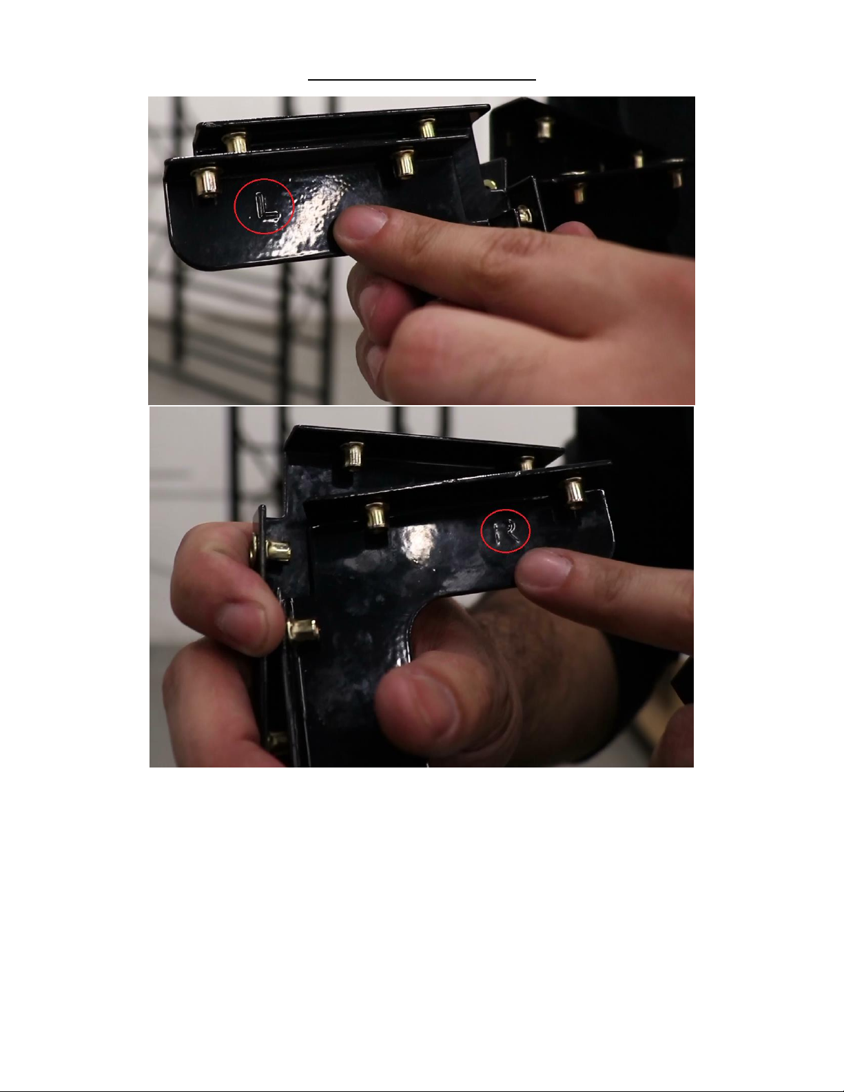
5. (4) L-shaped brackets. (2) “L” for left side and (2) “R” for right side.
6. (4) Small flat side brackets.
7. (28) Clear plastic storage bins.
8. Hardware Kit Containing –(28) Long Screws, (4) Short Screws, (12) Washers, and (20)
Small Ring Washers. *There may be extra screws included for replacements. *

10.(1) Top cover.
Now that all of your components have been separated and organized in your
workspace, you should find it very easy to make sure that all of your quantities are
correct on all pieces. This will also help you in finding whichever piece it is that you’ll
need to grab quickly, and at a glance for each step of assembly.

Identifying Legs Prior to Assembly
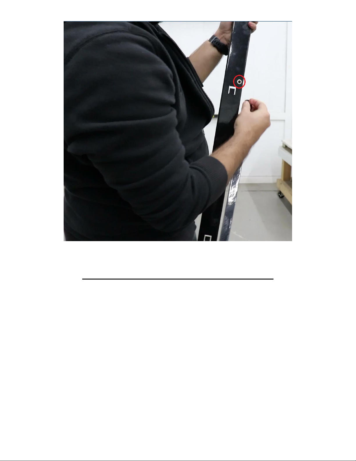
Start with the legs by looking at how they are numbered on the bottom ends. Labels on legs
will be numbered (1) through (4). The end with the number will serve as the bottom of the
rack. Legs that are numbered (1) and (2) should act as the front legs, and legs (3) and (4) will
serve as the back legs. Legs on left side should be paired as (1 & 4) and the right side as (2 &
3).
Begin assembly by laying two of the leg pieces, either legs (1 & 4) or (2 & 3) parallel to each
other on the floor. Make sure to lay the leg pieces with the inner-channel (inside) facing down.
The legs that are laid down, should have two threaded insert holes that are close together.
The second leg across should have two threaded insert holes that are spread further apart.
The edges on both legs that have the threaded insert holes, should be closest to center
space between the two legs.
Attaching Side Support Brackets to Legs
Next, from the hardware kit, grab (4) long screws and (4) washers for the first set of legs.
These will be used to secure the side brackets onto the side of the legs.
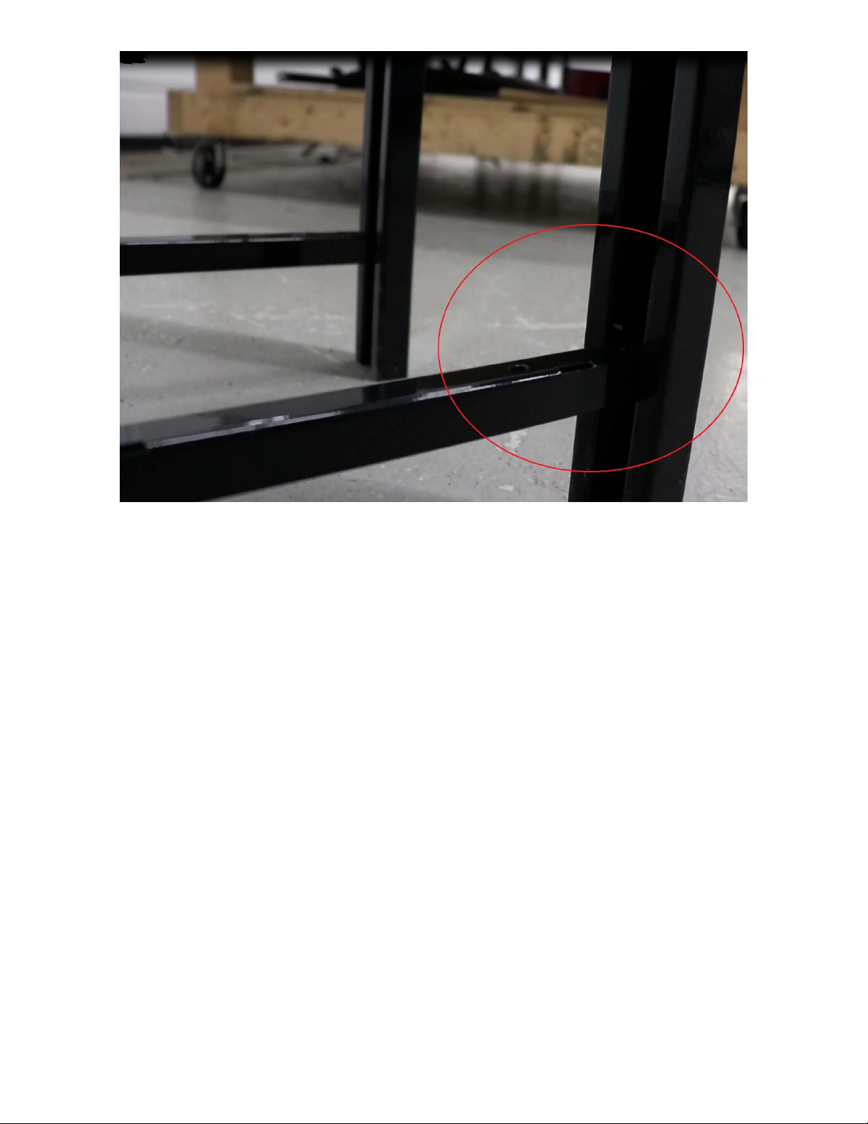
After you have grabbed your screws and washers, you will need to grab (2) flat support
brackets. Attach one end on one leg and the opposite end on the other.

Line up the holes on the brackets with the threaded insert holes on the legs at an angle. Be
sure not to tighten brackets too much, as they will need to be able to slightly move for proper
alignment. Once they are aligned properly, they may be fully tightened to secure them into
place.
(Attaching the brackets is done easiest when laying the pieces flat on the floor or a table top,
then tightening them together. This allows easier alignment adjusting.)
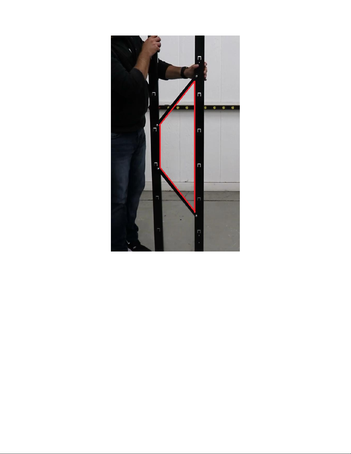
Once again, it is best to not fully tighten these in the beginning, as you will need to be able to
adjust and flex the brackets. When the legs are repositioned and leveled correctly, fully tighten
to secure the brackets to the legs. Once this step is complete, you will essentially have formed
a trapezoid-shaped space in the center of the two legs. These brackets will act as stabilizers to
keep the shelving upright. These brackets also help support and evenly distribute added
weight from items being stored on the rack. Avoid using too much power if using a screw gun,
as this may strip the threads of the inserts.
(Repeat the step you just completed with the second set of legs.)
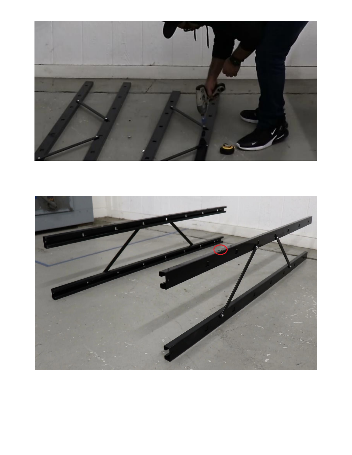
Flip both sets of legs onto their side so that the threaded insert is on top. This will be the back
side of the rack, where (2) long support brackets will be bolted down to add support.

Attaching Back Support Brackets to Legs
Grab (2) of the long flat brackets, (4) long screws and (4) washers. Similar to how the legs
support brackets are attached, the same will be done with the back brackets, connecting the
two sets of legs together.
When attached correctly, the brackets will cross over each other forming an “X” shape on the
back side. Again, make sure that the screws are not too tight, as you may need to adjust the
placement of the brackets and level the rack. Be sure to line up the bracket holes with the
threaded insert holes, similar to what was done with the legs.
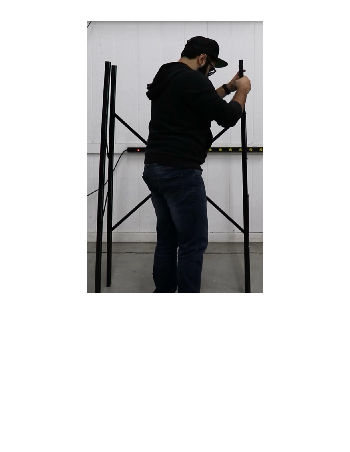
Now that the legs have all of the side and back support brackets attached and tightened, stand
the rack frame upright on the floor.

Setting Cross-beams on Rack
Next, gather the (14) cross-beams. (7) for the front and (7) for the back. On the cross-beams,
you will notice there are slots spaced throughout them, and the slots on the ends will have
two holes on each side as indicated. The slots must face up towards the ceiling and should be
on the outside edges, facing away from the center of the rack.
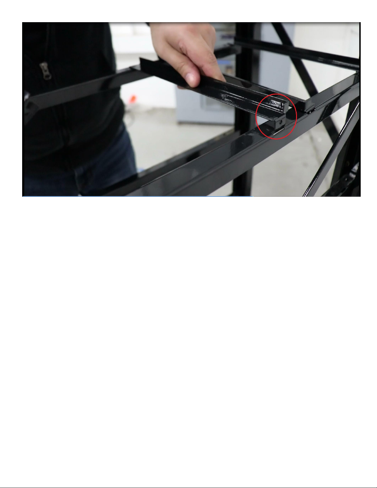
Raise one end of a cross-beam within the inner-channel of one leg, as you hook the opposite
end that is pointed downward onto the opposite leg, on the legs inner-channel tab. There is a
tab on each side, on the inner-channels that the ends of the cross-beams will slide into.
These tabs are spaced evenly by tier (7per each leg.) These will allow for the cross-beams to
interlock into place. Once one end is locked, slide the opposite end down the channel to also
lock that end into place. Doing this step correctly will allow the cross-beam to sit flush
between the legs. To ensure that they are connected properly, gently push the top of each end
downward, making sure that it doesn’t budge. The edges of the cross-beam with the slot,
should be facing towards the outside of the rack on both the front and back sides.
Installing L-brackets
Now that the cross-beams have been set into place, grab (16) long screws and (16) small ring
washers that will be used to fasten the “L”-shaped brackets to the cross-beams and front legs.
The (4) L-brackets will have (2etched with “L” and 2etched with “R” equaling 4in total.)
These will only be placed on the front side of the rack legs, on the top and second from the
bottom tiers cross-beam. All of the cross-beams come designed with L-bracket holes, so don’t
worry about only having (4) L-brackets or which cross-beams that you use, only (4) are
required for this particular rack model.

You can choose to start either from the top and either the left or the right side, when installing
the L-brackets.
Place the corner of the L-bracket underneath the cross-beam and in the inner-channel of the
leg. The flat side of the L-bracket should be facing towards the outside of the rack (or towards
you) while installing. Make sure that the threaded insert holes on the L-brackets line up with
two top holes of the cross-beam, and the two side holes of the leg.
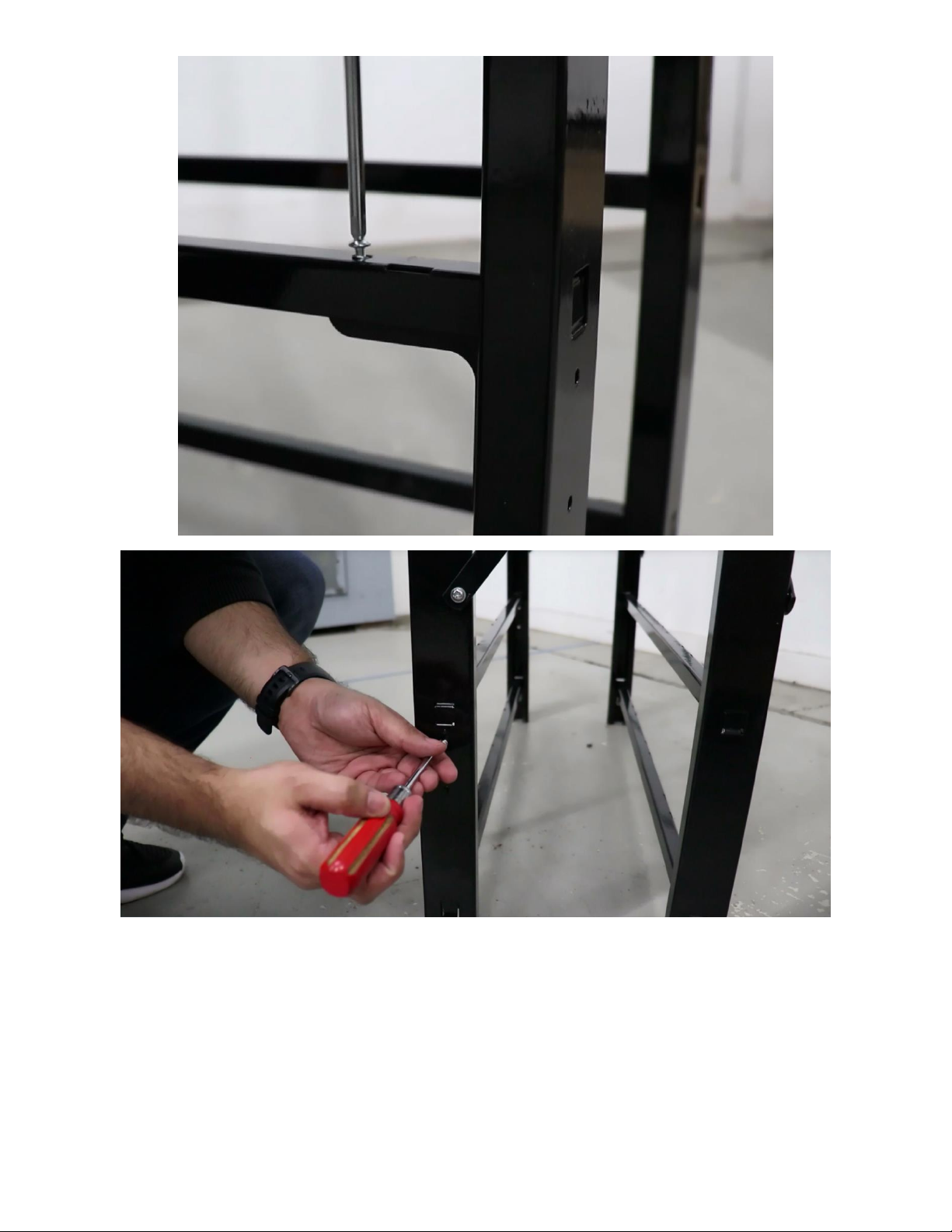
Secure the L-bracket with a ring washers and screws, but do not fully tighten just yet, as you
will need the space for wiggle room for another piece later. Gently push downwards on the
ends of the cross-beams where L-brackets were fastened, to ensure that they are flush and
locked in place.
Setting Bin Tracks
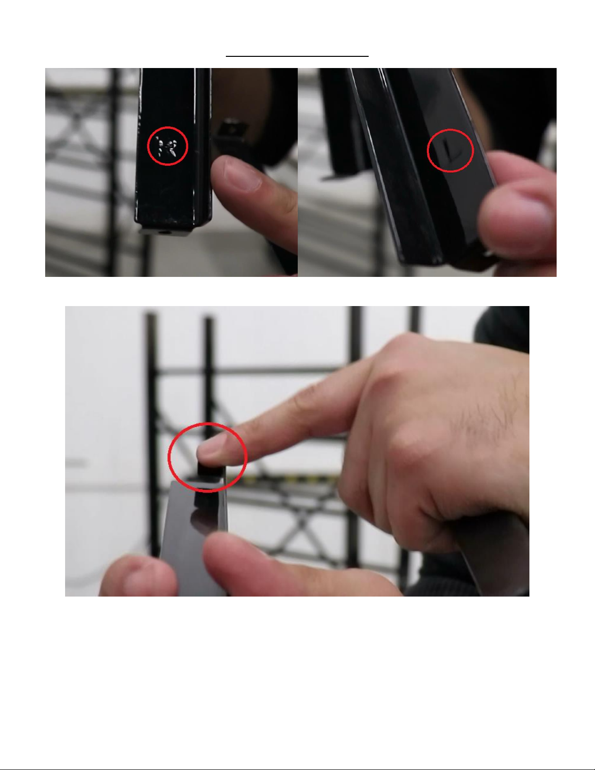
Next, you will need (56) tracks. (28 for the left side etched with “L” and 28 for the right side
etched with “R”). These tracks will have tabs that point downward and are to be inserted in
the rear and front cross-beam slots. Each track will have one open end that is to face out on
the front side, while the other end has a back-stop tab, that faces towards the rear side of the
rack.
Going from left to right, the “L” track and the “R” will alternate as you insert the tracks across
the beam and vice versa. Continue to do this until every slotted section has been filled on the
cross-beams for each tier. (4“L” Tracks and 4 “R” tracks per tier.)

Setting Top Shelf (Dust Cover)
Grab the top dust cover piece and make sure to set each corner portion over the top of each
leg. When the top is flush over the legs, and the holes are lined up, fasten the top piece to the
legs with your (4) remaining short screws. Slightly push upwards from the bottom side of the
top cover, to make sure that the piece is firmly attached.

Completing Assembly
Grab your stack of (28) bins and slide them onto the tracks of the parts rack, with the lipped
end being on the front side.
Bins will easily be able to slide in and out for convenient access.
Table of contents
Popular Tools Storage manuals by other brands


Workzone
Workzone 99609 Assembly instructions

Sjobergs
Sjobergs ORIGINAL 1100 Assembly instructions

Tennsco
Tennsco Industrial Workbench with Hardwood Butcher Block... Assembly Instructions/Parts Manual

Festool
Festool CS 70 VL Assembly instructions

WilTec
WilTec 50796 Operation manual

Bahco
Bahco MS7056ENG brochure


