manuals.online logo
Brands
  1. Home
  2. •
  3. Brands
  4. •
  5. Pantron
  6. •
  7. Amplifier
  8. •
  9. Pantron ISM-1000 User manual

Pantron ISM-1000 User manual

Bedienungsanleitung
1-Kanal Lichtschrankenverstärker
ISM-1000(S), ISM-1100(S)
Operating Instructions
1-channel light barrier amplier
ISM-1000(S), ISM-1100(S)
1/2OI140307DE/EN
Alle technischen Angaben beziehen sich auf den Stand 12/2015. Änderungen bleiben vorbehalten.
All technical specications refer to the state of the art 12/2015. They are subject to modications.
Sicherheitshinweise
Der Einsatz von Infrarot-Verstärkern ISM... ist nicht zulässig für Anwendungen,
bei denen die Sicherheit von Personen von der Gerätefunktion abhängig ist.
Der Betreiber des übergeordneten Systems, z.B. einer Maschinenanlage, ist
für die Einhaltung der nationalen und internationalen Sicherheits- und Unfall-
verhütungsvorschriften verantwortlich.
• Einleitung
Die Lichtschrankenverstärker werden zur Erkennung von Objekten in Maschinen oder
Produktionsanlagen eingesetzt. Sie bilden in Verbindung mit einem Infrarotsender IT...
und Infrarotempfänger IR... (nicht im Lieferumfang) eine leistungsstarke Lichtschranke
und sind einsetzbar in Bereichen mit hoher Reichweite oder Verschmutzung.
• Arbeitsweise
Das ISM-1000(S), ISM-1100(S) ist ein 1-Kanal Verstärker mit manueller
Verstärkungseinstellung mittels Potentiometer (S = Schraubklemmen-, sonst
Steckverbinder-Anschlüsse).
Der Verstärker arbeitet mit moduliertem Infrarotlicht, wodurch eine hohe Sicherheit
gegen Fremdlicht erreicht wird. Die Schaltung ist so ausgelegt, daß nur Signale
richtiger Frequenz und Phasenlage erkannt werden. Dadurch ist eine Beeinussung
durch andere Lichtschranken nahezu ausgeschlossen.
Der Typ ist zusätzlich mit einer Alarm-Funktion und dazugehörigem Alarmausgang
ausgestattet. Außerdem kann die Sendeleistung reduziert, die Sendefrequenz variiert
und das Schaltverhalten invertiert werden.
• Installation
Der Verstärker darf senkrecht und waagerecht auf eine Tragschiene (EN 60715)
montiert werden. Geräte, die schädliche Wärme abgeben, sind in einem Abstand von
min. 20 mm zu platzieren (Betriebstemperatur: -25 °C ... +50°C). Für den elektrischen
Anschluss ist oben und unten ein Abstand von mindestens 15 mm zu anderen Teilen
einzuhalten. Die Betriebsspannung des Verstärkers beträgt 24 V DC ± 20 %.
Safety instructions
The operation of infrared amplier ISM... is not authorized for applications
where the safety of a person depends on the function of the device.
The operator of the higher-level overall system, e.g. a machine installation,
is responsible for complying with the national and international safety and
accidentpreventionregulationswhichapplytothespecicuse.
• Introduction
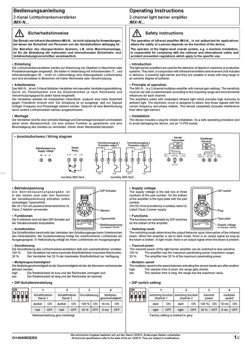
The light barrier ampliers are used for the detection of objects in machines or
production systems. They form, in conjunction with one infrared transmitter and receiver
(not included in delivery), a powerful light barrier and they are useable in areas with
long range or an extreme degree of pollution.
• Principle of operation
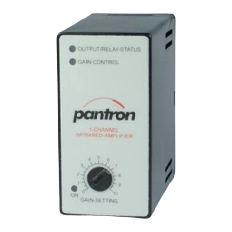
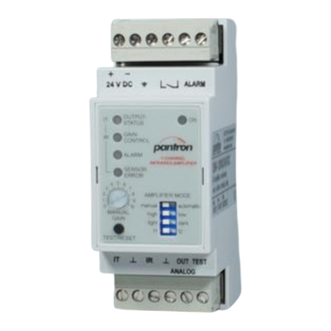
The ISM-1000(S), ISM-1100(S) is a 1-channel amplier with manual gain setting by
potentiometer (S = Screw terminals, otherwise plug-in connectors).
The amplier works with modulated infrared light which provides high immunity to
ambient light. The electronic circuit is designed to detect only those signals with the
correct frequency and phase relation. This almost completely excludes interference
from other light barriers.
The special features of type are an alarm function with alarm output, adjustable
transmit power (high / low), 4 transmit frequencies and invertable switching behavior
(light / dark ).
• Installation
It is acceptable to mount the amplifier using a DIN rail (EN 60715) vertically or
horizontally. Devices that release dangerous heat must be mounted at a distance of
at least 20 mm (operation temperature: -25°C (-13°F) ... +50°C (+122°F). For electrical
connection a distance of at least 15 mm from top and bottom of the device to other
parts is needed. The supply voltage of the device is 24 V DC ± 20 %.
24V DC
Betriebsspannung
Power supply
2
13
PE
24 VDC±20%
2
Erde
earth
Alarmausgang
alarm output
*)
*)
6
24 V/100 mA
Schaltausgang
switching output
5
4
Last
load
60 V/100 mA
Sender
Transmitter
Rot
red
Schwarz
black
Empfänger
receiver
Gelb
yellow
Schirm
shield
10
9
8
711 12
Testeingang
test input
24V DC / 2mA
~~
NC
*)
Alarmausgang nur / Alarm output only ISM-1100(S)
untere Anschlüsse/bottom connections
obere Anschlüsse/top connections
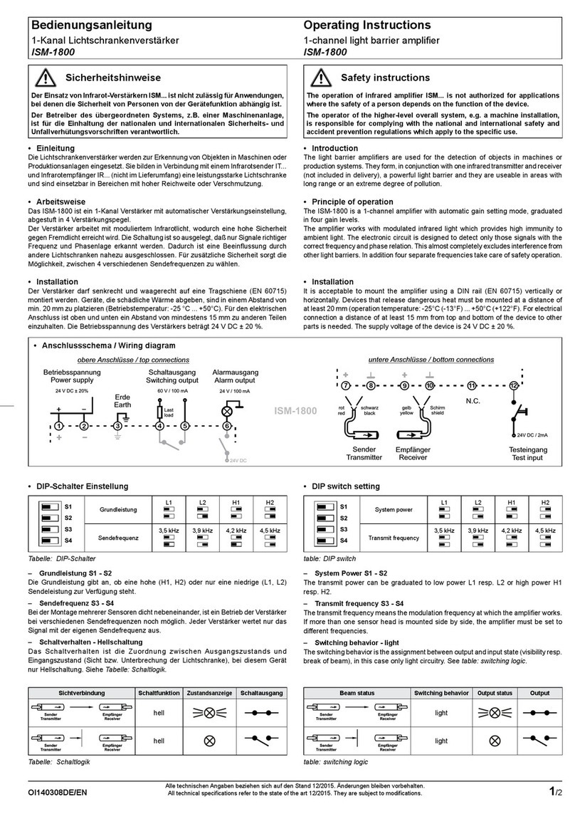
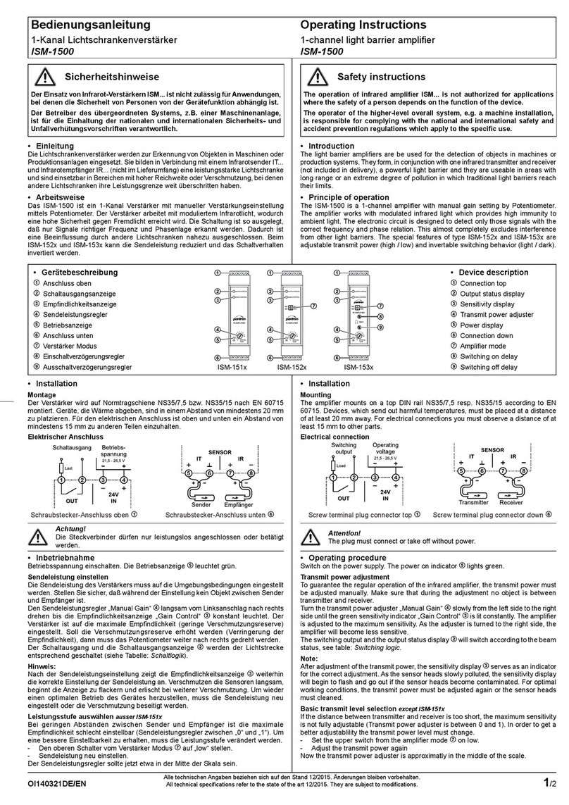
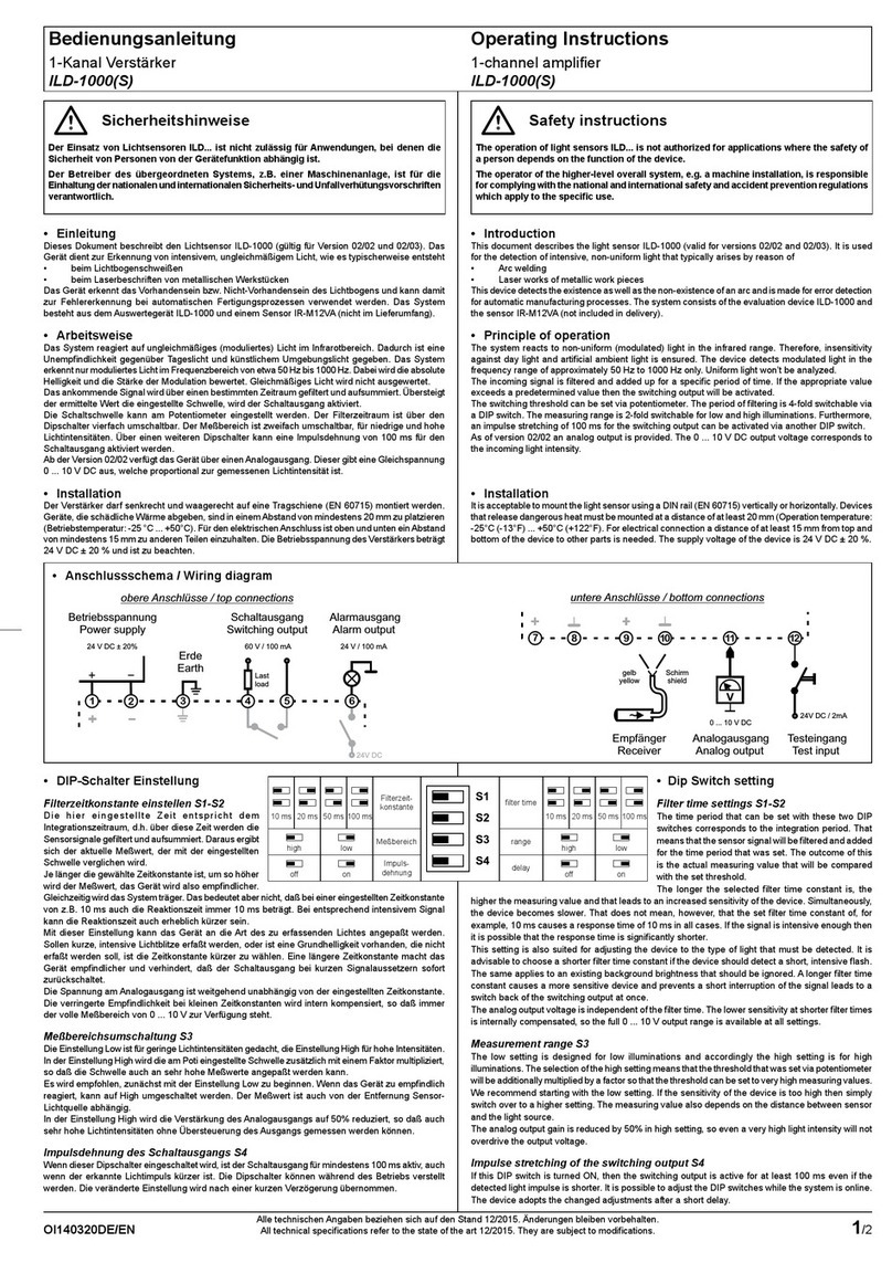
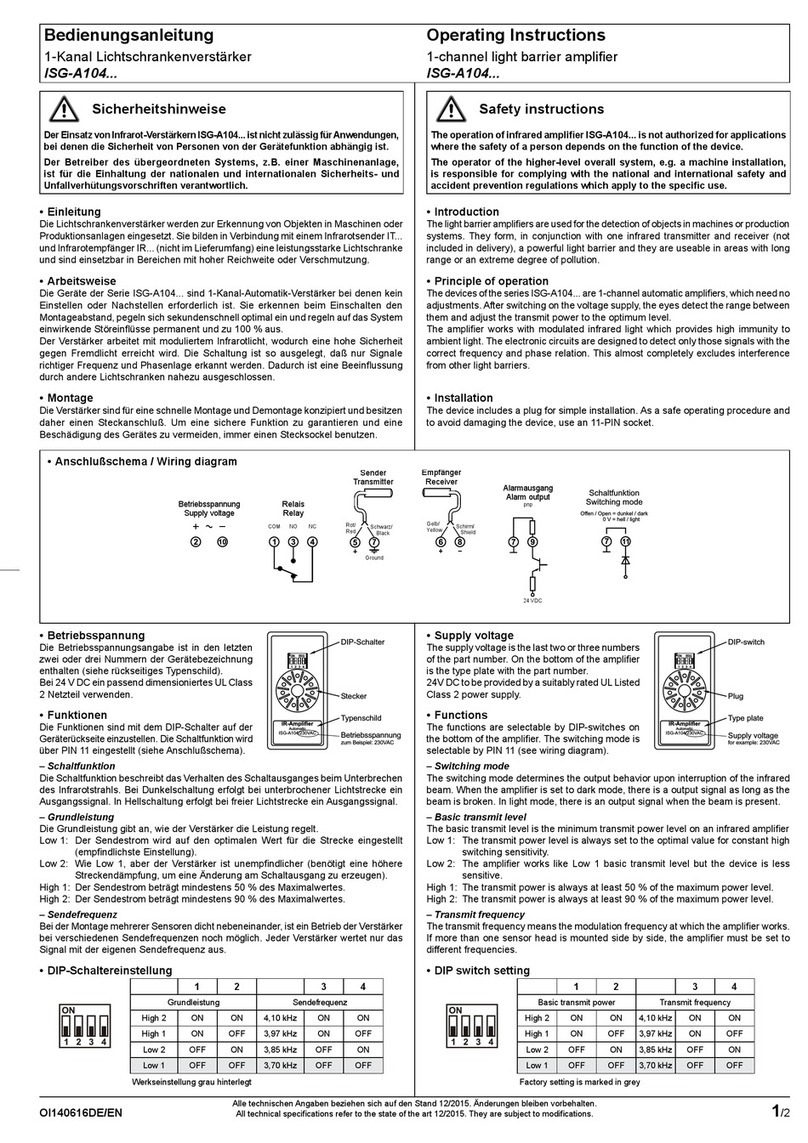
• DIP-Schalter Einstellung ISM-1100(S)
S1
S2
S3
S4
S1 - Grundleistung high low
S2 - Schaltverhalten hell dunkel
S3 / S4 - Sendefrequenz
3,5 kHz 3,8 kHz 4,0 kHz 4,5 kHz
Tabelle: DIP-Schalter
– Grundleistung S1
Die Grundleistung gibt an, ob die volle (high) oder nur eine verminderte (low)
Sendeleistung zur Verfügung steht.
– Schaltverhalten S2
Das Schaltverhalten dient der Einstellung des Ausgangszustands bei Sicht bzw.
Unterbrechung der Lichtschranke (siehe Tabelle: Schaltlogik).
– Sendefrequenz S3-S4
Bei der Montage mehrerer Sensoren dicht nebeneinander, ist ein Betrieb der Verstärker
bei verschiedenen Sendefrequenzen noch möglich. Jeder Verstärker wertet nur das
Signal mit der eigenen Sendefrequenz aus.
Sichtverbindung Schaltfunktion
Zustandsanzeige
Schaltausgang
Sender
Transmitter
Empfänger
Receiver
hell
dunkel
Sender
Transmitter
Empfänger
Receiver
hell
dunkel
Tabelle: Schaltlogik
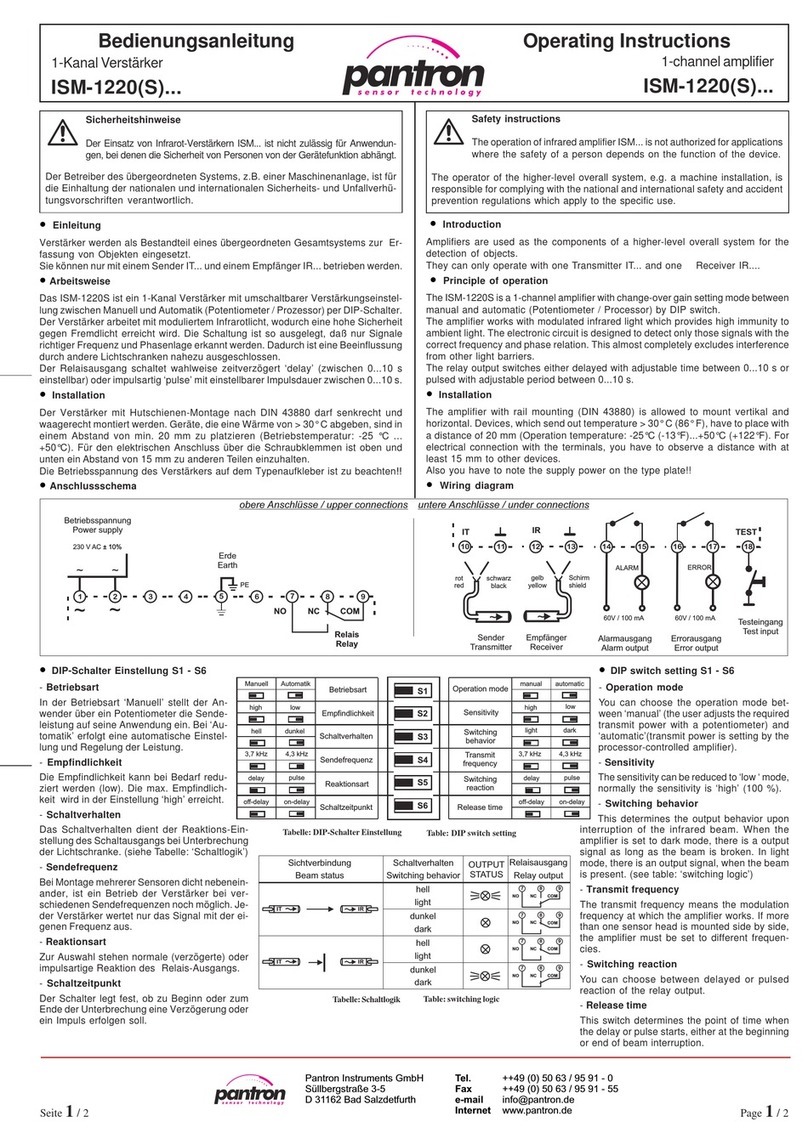
• DIP switch setting ISM-1100(S)
S1
S2
S3
S4
S1 - System power high low
S2 - Switching behavior light dark
S3 / S4 - Transmit
frequency
3,5 kHz 3,8 kHz 4,0 kHz 4,5 kHz
table: DIP switch
– System power S1
The transmit power can be reduced to low power, normally the value is high (100 %).
– Switching behavior S2
This determines the output behavior. When the amplier is set to dark mode, there is
a output signal as long as the beam is broken. In light mode, there is an output signal,
when the beam is present (see table: switching logic).
– Transmit frequency S3-S4
The transmit frequency means the modulation frequency at which the amplier works.
If more than one sensor head is mounted side by side, the amplier must be set to
different frequencies.
Beam status Switching behavior
Output status
Output
Sender
Transmitter
Empfänger
Receiver
light
dark
Sender
Transmitter
Empfänger
Receiver
light
dark
table: switching logic
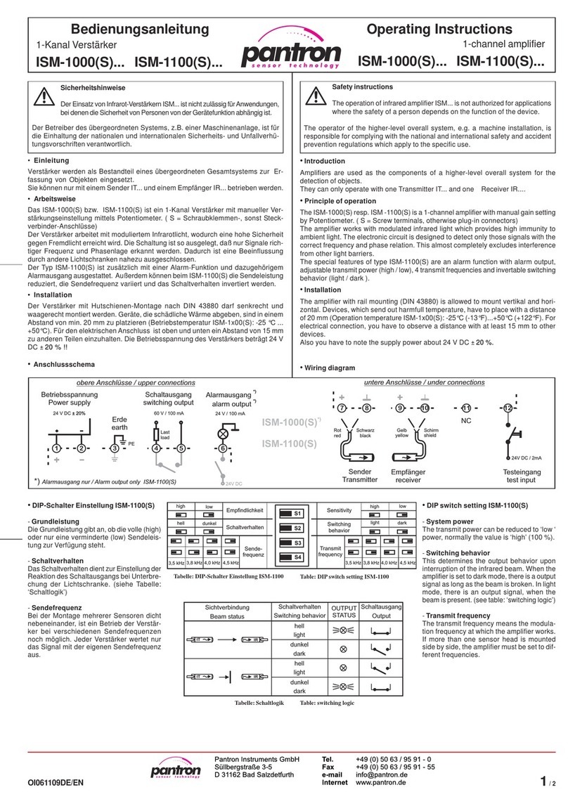
• Anschlussschema / Wiring diagram
2/2
• Inbetriebnahme
Vor Inbetriebnahme DIP-Schalter S1 - S4 am Gerät passend einstellen nur ISM-1100(S).
Sensoren aufeinander ausrichten.
Nach Anlegen der Betriebsspannung die Sendeleistung mit P1 auf die erforderliche
Höhe bringen, sodass bei Sichtverbindung H2 leuchtet. In Hellschaltung leuchtet
gleichzeitig H1, während in Dunkelschaltung nur ISM-1100(S) H1 erst bei Unterbrechung
aueuchtet (siehe Tabelle: Schaltlogik).
• Alarm und Alarmausgang nur ISM-1100(S)
Der Alarmzustand tritt ein, wenn die Sendeleistung nicht ausreichend ist. Ursache
kann z. B. eine Verschlechterung der Sicht, eine zu große Distanz oder Dejustage der
Sensoren sein. Nach Beseitigung des Fehlers erlischt die Anzeige.
• Testeingang
Legt man an den Testeingang 24 V DC an, so schaltet der Sender ab. Es kann so die
Funktion der Lichtschranke überprüft werden.
• Operating procedure
Before operating procedure you have to choose the DIP switch setting S1 - S4 for your
application only ISM-1100(S). Sensor heads adjusts one on top of the other.
After switch on the power supply, you have to adjust the transmit power with P1 until
H2 signals sufcient power. In light switching mode H1 lights too whereas in dark
switching mode only ISM-1100(S) H2 lights only, when the beam is interrupted (see also
table: Switching logic).
• Alarm and Alarm output only ISM-1100(S)
Alarm is active, when the transmit power is not sufcient. The cause can be e. g.
deterioration of the beam, too large distance or misadjustment of sensor heads. Is the
cause removed, the alarm is no longer active.
• Test input
A voltage with a value of 24 V DC at test input switches off the transmitter beam. With
this feature you can test the system.
Technische Daten (bei 20 °C, Ub= 24 V DC) ISM-1000(S), ISM-1100(S) Technical data (at 20 °C (68 °F), Vs= 24 V DC)
Betriebsspannung 24 V DC / ± 20% / 2,4 W Supply power
Messverfahren moduliertes IR-Licht modulated IR-light Operating basis
Maximale Reichweite (Einweg) Empfänger / Receiver IRL-... Empfänger / Receiver IRH-..., IR-... Maximum range (Through beam)
Sender ITL-..., IT-... 7 m (23 ft) 15 m (49 ft) Transmitter ITL-..., IT-...
Sender ITH-..., IT-...HP 10 m (33 ft) 25 m (82 ft) Transmitter ITH-..., IT-...HP
Sender ITA-... 20 m (66 ft) 55 m (182 ft) Transmitter ITA-...
Sendefrequenz 3,5 kHz / 3,8 kHz / 4,0 kHz / 4,5 kHz Transmit frequency
Sendeleistung manuell manual Transmit power
Schaltfunktion bzw. Schaltverhalten hell / dunkel light / dark Switching behavior
Grundleistung high / low System power manual mode
Schaltverzögerung / Impulsbreite —Switching delay / impulse period
Schaltausgang (kurzschlussfest) Schließer (Halbleiter-Relais) NO (Semiconductor-Relay) Switching output (short-circuit proof)
Schaltwerte maximal 100 mA / 60 V AC (DC) Maximum values
Reaktionszeit 24 ms Reaction time
Alarm-/Errorausgang (kurzschlussfest) nur ISM-1100(S) pnp: 100 mA / 24 V DC Alarm / Error output (short-circuit proof) only ISM-1100(S)
Analogausgang — Analog output
Testeingang Active HIGH (L= 0 ... 5 V DC, H= 15 ... 30 V DC) Test input
Gehäusewerkstoff NORYL RAL 7035 (grau / grey) Housing material
Schutzart IP 20 Protection class
Anschluss-Querschnitt 0,14 ... 2,5 mm² Terminal size
Maximale Kabellänge (Sensor-/Signalanschlüsse) 30 m Maximum cable length (sensor and signal connections)
Betriebstemperatur -25 °C ... +50 °C (-13 °F ... +122 °F) Operating temperature
Gehäuseabmessungen siehe Maßzeichnung see dimensions Housing measurements
Prüfungen Approvals
• Anzeigen und Bedienelemente
H1: Schaltzustandsanzeige - gelb
H2: Empndlichkeitsanzeige - grün
H3: Betriebsanzeige - grün
H4: Alarmanzeige - rot
P1: Empndlichkeitseinsteller
S1 - S4: DIP-Schalter Einstellungen
H1
H2
P1
S1 - S4
IR-AMPLIFIER
OUTPUT-
STATUS
GAIN-
CONTROL
ALARM
ON
light
high
dark
low
MANUAL
GAIN
AMPLIFIER MODE
f1=1+3
f2=1+4
f3=2+3
f4=2+4
12
43
H3
H4
H1
H2
P1
OUTPUT-
STATUS
GAIN-
CONTROL
ON
MANUAL
GAIN
IR-AMPLIFIER
H3
•Displays and controls
H1: Switching indicator - yellow
H2: Sensitivity display - green
H3: Power On display - green
H4: Alarm display - red
P1: Gain setting
S1 - S4: DIP-switch settings
Steckverbinder / plug-in connector
35,8
9,5
58
89,6
95
• Maßzeichnungen / Dimensions in mm
35,8
9,5
89,6
95
58
ISM-1000(S) ISM-1100(S)
(S) Schraubanschlüsse / screw terminals
Pantron Instruments GmbH
Süllbergstraße 3-5
D-31162 Bad Salzdetfurth
Tel. +49 (0) 5063 / 9591-0
Fax +49 (0) 5063 / 9591-55
E-mail [email protected]
Internet www.pantron.de

This manual suits for next models

3

Other Pantron Amplifier manuals

Pantron ISG-A101 User manual

Pantron

Pantron ISG-A101 User manual

Pantron ISG-A1 Series User manual

Pantron

Pantron ISG-A1 Series User manual

Pantron ISM-1200 User manual

Pantron

Pantron ISM-1200 User manual

Pantron ISM-1800 User manual

Pantron

Pantron ISM-1800 User manual

Pantron ISM-4800 User manual

Pantron

Pantron ISM-4800 User manual

Pantron ISG-A104 Series User manual

Pantron

Pantron ISG-A104 Series User manual

Pantron ISM-8800 User manual

Pantron

Pantron ISM-8800 User manual

Pantron ISM-1000 Series User manual

Pantron

Pantron ISM-1000 Series User manual

Pantron ISM-2000 User manual

Pantron

Pantron ISM-2000 User manual

Pantron ISM-1500 User manual

Pantron

Pantron ISM-1500 User manual

Pantron ISG-A1 Series User manual

Pantron

Pantron ISG-A1 Series User manual

Pantron ISM-4000 User manual

Pantron

Pantron ISM-4000 User manual

Pantron IMX-N Series User manual

Pantron

Pantron IMX-N Series User manual

Pantron ISG-N Series User manual

Pantron

Pantron ISG-N Series User manual

Pantron ISM-8000 Series User manual

Pantron

Pantron ISM-8000 Series User manual

Pantron ISM-1220S User manual

Pantron

Pantron ISM-1220S User manual

Pantron ISG-N124M User manual

Pantron

Pantron ISG-N124M User manual

Pantron ILD-1000(S) User manual

Pantron

Pantron ILD-1000(S) User manual

Pantron ISG-N1 Series User manual

Pantron

Pantron ISG-N1 Series User manual

Popular Amplifier manuals by other brands

Digilent PmodAMP2 Reference manual

Digilent

Digilent PmodAMP2 Reference manual

Altinex DA1706SV user guide

Altinex

Altinex DA1706SV user guide

TC Electronic COMBO DELUXE 65' quick start guide

TC Electronic

TC Electronic COMBO DELUXE 65' quick start guide

XINDAK XA8800MNE instructions

XINDAK

XINDAK XA8800MNE instructions

B&K 1606 Instructions and applications

B&K

B&K 1606 Instructions and applications

Crown MA-9000i Specifications

Crown

Crown MA-9000i Specifications

Clarion APX200 Operating & installation manual

Clarion

Clarion APX200 Operating & installation manual

Inter-m IM-300 Operation manual

Inter-m

Inter-m IM-300 Operation manual

Roland KC-150 Specifications

Roland

Roland KC-150 Specifications

Belden Grass Valley VEA-1023 Guide to installation and operation

Belden

Belden Grass Valley VEA-1023 Guide to installation and operation

Vox Night Train 50H G2 owner's manual

Vox

Vox Night Train 50H G2 owner's manual

Linear Technology LTC6430-20 Demo Manual

Linear Technology

Linear Technology LTC6430-20 Demo Manual

Speco PAT-20TB instruction manual

Speco

Speco PAT-20TB instruction manual

Link electronics Video Distribution Amplifier IEC-750 Specification sheet

Link electronics

Link electronics Video Distribution Amplifier IEC-750 Specification sheet

Unisound TC-30 Operation manual

Unisound

Unisound TC-30 Operation manual

NAD C340 Service manual

NAD

NAD C340 Service manual

C-Tech Pocket Rockit S1 owner's manual

C-Tech

C-Tech Pocket Rockit S1 owner's manual

Technics SU-X901 - service Service manual

Technics

Technics SU-X901 - service Service manual

manuals.online logo
manuals.online logoBrands
  • About & Mission
  • Contact us
  • Privacy Policy
  • Terms and Conditions

Copyright 2025 Manuals.Online. All Rights Reserved.