ETB Pegasus User manual

Page 1 of 31
Limb Phasing System
User Guide
V5-6-5
July 2010

Page 2 of 31
Table of Contents
1.Introduction ............................................................................................................2
2.Glossary..................................................................................................................3
3.Sensors - essential information (extract from the Sensors Manual):......................3
4.Poseidon software – a brief introduction:...............................................................5
5.Sequence of operations (overview):.......................................................................7
6.Preparation the day before a trial:...........................................................................7
7.Preparation immediately before a trial:................................................................10
7.1.Preparation for a trial when the GPS speed, location and stride length data
are required ..............................................................................................................10
7.2.Preparation for a trial when only stride duration and limb phasing is required
11
8.Dual Sensor system ..............................................................................................12
8.1.How to operate a dual Sensor System...........................................................12
9.Performing a trial:.................................................................................................13
9.1.Pegasus-S placement:....................................................................................13
9.2.Pegasus-I placement: ....................................................................................14
10.Retrieving and analysing data from the trial:....................................................17
10.1.Retrieving and analysing data from the trial with GPS speed data:..........20
10.2.Retrieving and analysing data from the trial without GPS data:...............21
11.Presenting the results ........................................................................................22
11.1.Tabular presentation:.................................................................................22
11.2.Plotting the data.........................................................................................22
11.3.Saving the data: .........................................................................................27
11.4.Preparing a report: .....................................................................................27
11.5.Creating PDF of your report......................................................................27
12.Reviewing previous results:..............................................................................28
13.Storing data for later analysis or clearing data from the sensors:.....................28
14.Obtaining the results from saved data:..............................................................29
14.1.Obtaining data from a trial with GPS speed data ......................................30
14.2.Obtaining data from a trial without GPS speed data:................................30
15.Using a new memory card in Pegasus-I:..........................................................30
16.Calibration: .......................................................................................................30
17.To get help from ETB:......................................................................................31
18.Frequently Asked Questions.............................................................................31
1. Introduction
This user guide is intended to take you through the process of using the Pegasus Limb
Phasing System to gather data on a horse’s gait, retrieving that data, and finally
analysing it.
It covers all routine operations, and with sufficiently frequent use, you will need it
less and less.
If you are curious and want to know a little more about the sensors, or if you observe
something you feel is out of the ordinary, please refer to the Sensors Manual and/or

Page 3 of 31
the Getting Started & Support document, which are included with your system.
Essential information about them is included below.
If you feel we have not been clear or correct, please do let us know so we can
improve!
2. Glossary
csv = comma separated variable
GPS = Global Positioning System
HTML = HyperText Mark-up Language
LED = Light Emitting Diode, the type of indicator on the sensors.
NiMH = nickel metal hydride, referring to types of battery used
PC = Personal Computer
.pdf = file in Portable Document Format (by Adobe Systems)
SD = Secure Digital (memory card)
Trial = a test, using the Pegasus Limb Phasing System to gather and analyse data
USB = Universal Serial Bus
3. Sensors - essential information (extract from the Sensors
Manual):
Batteries and charging:
DO recharge Pegasus-I and Pegasus-S’s battery overnight to be sure the batteries
will give you the maximum logging time. Check the battery indicator LEDs to
make sure that charging is actually taking place! Note that Pegasus-I is never
actually turned completely off, so will charge whenever connected to a suitable
power source.
DON’T leave the Pegasus units on charge indefinitely – ideally stop after 12
hours and aim for no more than 16 hours, whatever the state of the battery LED
indicator.
DON’T leave the Pegasus units for more than 1 month without charging the
battery.
DON’T charge the Pegasus units from the notebook PC running off its internal
battery. This either won’t work, or will drain the notebook battery.
DO charge at normal room temperature and avoid hot environments for charging.

Page 4 of 31
When fully charged, the sensors will log for a duration of around 6 hours.
Batteries and end of product life:
The batteries in Pegasus-S are removable by releasing the battery compartment clip.
They are rechargeable nickel metal hydride (NiMH) cells and should be disposed of
through recognised channels (consult your local authority), as should the unit itself.
Neither should be placed in a domestic or industrial waste stream as they may end up
as landfill.
You may choose to return the Pegasus-S to ETB.
The battery in Pegasus-I is also rechargeable NiMH but is not removable. It is
permanently wired for maximum reliability and the end of life of the battery means
the end for Pegasus-I also. It should be returned solely to ETB for battery removal
and disposal.
Record only what is relevant:
It would be easy to leave the Pegasus units recording continuously. However, this
will produce a large amount of data that has no value but which will take ages to
pointlessly analyse.
So, stop the Pegasus units recording when the activity you wish to analyse has
ended.
Now we can start using the system in earnest!

Page 5 of 31
4. Poseidon software – a brief introduction:
Poseidon is the software that you need at every stage apart from actually recording
data and charging the sensors’ batteries.
To activate it, click on the Poseidon icon on the desktop:
This brings up the main screen:

Page 6 of 31
Note the soft key “buttons” to the left and the information below the centre of the
screen: it is worth pausing to read this information for each screen you encounter.
If you click on one of the “buttons”, a new screen appears: for example, Sensors has
been selected here:

Page 7 of 31
Notice how the selected button is now filled in, new information has appeared at
screen centre, and buttons which are inactive are “greyed out”.
Detailed use of Poseidon will be described below as operation is covered in detail.
5. Sequence of operations (overview):
Since it can be daunting to read through a whole set of instructions, we felt it may be
helpful to present the main essential process steps before describing them in detail.
They are:
Preparation the day before a trial: charging the sensor batteries. This is done with
the complete system.
Preparation immediately before a trial: the Poseidon software sets the sensor
clocks and synchronises them to each other (also done with complete system) and
should be done within 1 hour of doing the trial to avoid clock drift degrading the
results. This operation has two variations, depending on whether speed and stride
length are required, in which case the GPS unit is needed; otherwise it can be
omitted, giving limb phasing and stride rate only.
Carrying out the trial (collecting the data). This is done with the sensors away
from the rest of the system, mounted on the horse, and running on battery power.
Analysis of the collected data: under the control of the Poseidon software, the
recorded data are transferred from the sensors to the notebook PC and analysed.
The process will now be described in detail.
6. Preparation the day before a trial:
Open the case and check that all units are connected to their USB cable.
Check both USB connections are made to the notebook PC (these should never
normally be removed).
Ensure Pegasus-S unit is switched off.
Ensure the notebook PC power supply is connected and plugged into a power
socket.
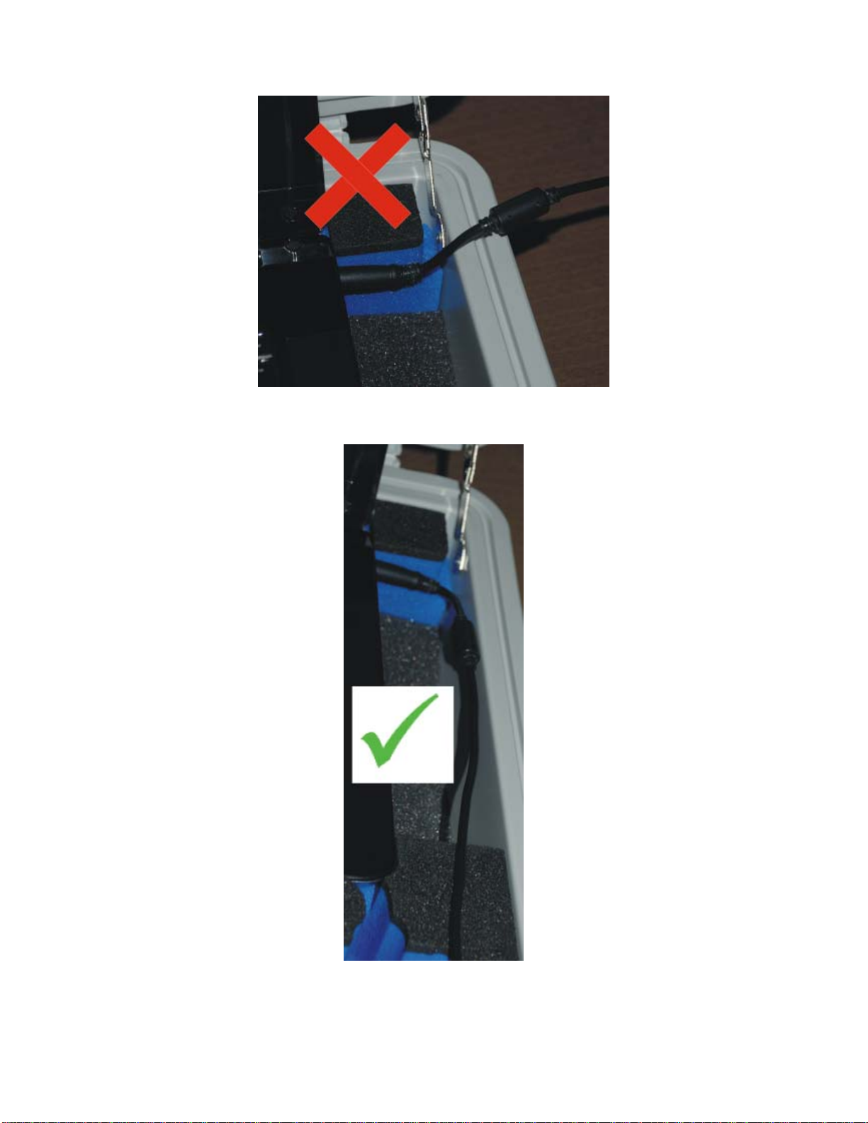
Take care not to trap the notebook PC power supply cable by
accidentally closing or slamming the case lid. Do NOT lead the
cable over the case side:
Page 8 of 31
Bend it so it runs parallel to the case side:
(The section of cable that plugs into the notebook PC carries non-hazardous low
voltage.)

Page 9 of 31
Switch on the notebook PC. (Poseidon software does not have to be running at
this stage.)
Leave overnight to enable the sensors to fully charge, which takes around 12
hours. The sensors should have the following LED indicators lit:
Pegasus-I amber charging LED (next to the battery symbol on the case). This
will remain on while the sensors are connected to the notebook PC with the
latter switched on (occasionally, this may change to blue but this is of no
consequence: charging is unaffected).
Pegasus-S red battery charging LED, which initially flashes three times, then
lights continuously until charged. This will extinguish when the unit is fully
charged.
(Reminder: for more information about the sensors refer to the Sensors Manual.)

Page 10 of 31
7. Preparation immediately before a trial:
(In the text that follows, Poseidon screen “buttons” are referred to in this form:
button.)
Open Poseidon by a double-click on the icon:
Set up the sensors by clicking on Sensors. There are then two options:
Set clocks to Pegasus-S
Set clocks to Computer
7.1. Preparation for a trial when the GPS speed, location and
stride length data are required
Positioning the Pegasus-S outdoors or near a window is generally needed, in order
to receive the required signals from several GPS satellites.
Switch on Pegasus-S (small slide switch).
Click on Set clocks to Pegasus-S.
The progress bar is then displayed, indicating that Pegasus-S is searching for a
satellite fix. This can take 15 minutes or maybe more if the unit has not been used in
this location previously, or if the signal strength is poor.
A steady flash from the blue LED indicates Pegasus-S is attempting to acquire
satellite signals, changing to a brief blink when accomplished. Be sure to take note of
the difference.
If more convenient, it is possible to take the Pegasus-S outside, acquire the satellites,
and then return it indoors and connect to the notebook PC and click on Set clocks
to Pegasus-S again.
If Pegasus-S loses the satellites whilst being set up indoors, take the whole system
outdoors and start the process again.
In rare instances, despite all sensors being connected correctly, an error message may
appear stating that insufficient sensors are connected.
Should this occur, click on Cancel, which takes you back to the main Sensors
screen.
Disconnect the two USB connectors from the PC, then reconnect them, then proceed
as normal.

Page 11 of 31
Once the satellite signals have been acquired, Prepare Pegasus-I Group
becomes enabled: click on this. The time stamp on each unit is displayed. At the
end of this procedure there are four tabs and a button at the top of the screen
indicating ‘Done’. To check the information for each unit, click on the tab for
each sensor in turn.
Note: the order of the on-screen tabs will generally not reflect the physical order of
the sensors in the case.
For each Pegasus-I sensor, the maximum recording time left, time and date set,
the current time and data, the device type, and the serial number, are all displayed.
Take a moment to check that these look correct for each of the four units before
proceeding.
If there is insufficient recording time on a sensor, click on Data. The files on the
card are then shown. To delete files, highlight them and then click on Delete.
When done, click on Sensors and you are returned to the set-up screen.
When all sensors have enough recording time for data collection, click on Done.
Prepare Pegasus S is then enabled: click on it. You are then advised that
previous speed data will be deleted. Select Yes, then Done. The units are now
ready for a trial.
Disconnect each of the sensors and proceed to the horse for the trial.
7.2. Preparation for a trial when only stride duration and limb
phasing is required
If only stride duration, gait and phase are required, choose Set clocks to
Computer:
Prepare Pegasus-I Group becomes enabled. Click on it: the progress of
setting the time stamp on each unit is displayed.
At the end of this procedure there are four tabs and a button at the top of the
screen indicating Done.
Note: the order of the on-screen tabs will generally not reflect the physical order of
the sensors in the case.
To check the information for each unit, click on the tab for each sensor in turn.
For each Pegasus-I sensor, the maximum recording time left, time and date set,
the time and data now, the device type and the serial number are all displayed.
Take a moment to check that these look correct for each of the four units before
proceeding.
Page 12 of 31
If there is insufficient recording time on a sensor, click on Data. The files on the
card are then shown. To delete files, highlight them and then click on Delete.
When done, click on Sensors and you are returned to the set-up screen.
When all sensors have enough recording time for data collection, click on Done.
Disconnect each of the sensors and proceed to the horse for the trial.
8. Dual Sensor system
Some users like to operate the equipment using two complete sets of sensors. Having
two sets of sensors allows the user to do the following;
Carry out a test on two horses at the same time.
Have a test being carried out whilst down loading a set of trial data.
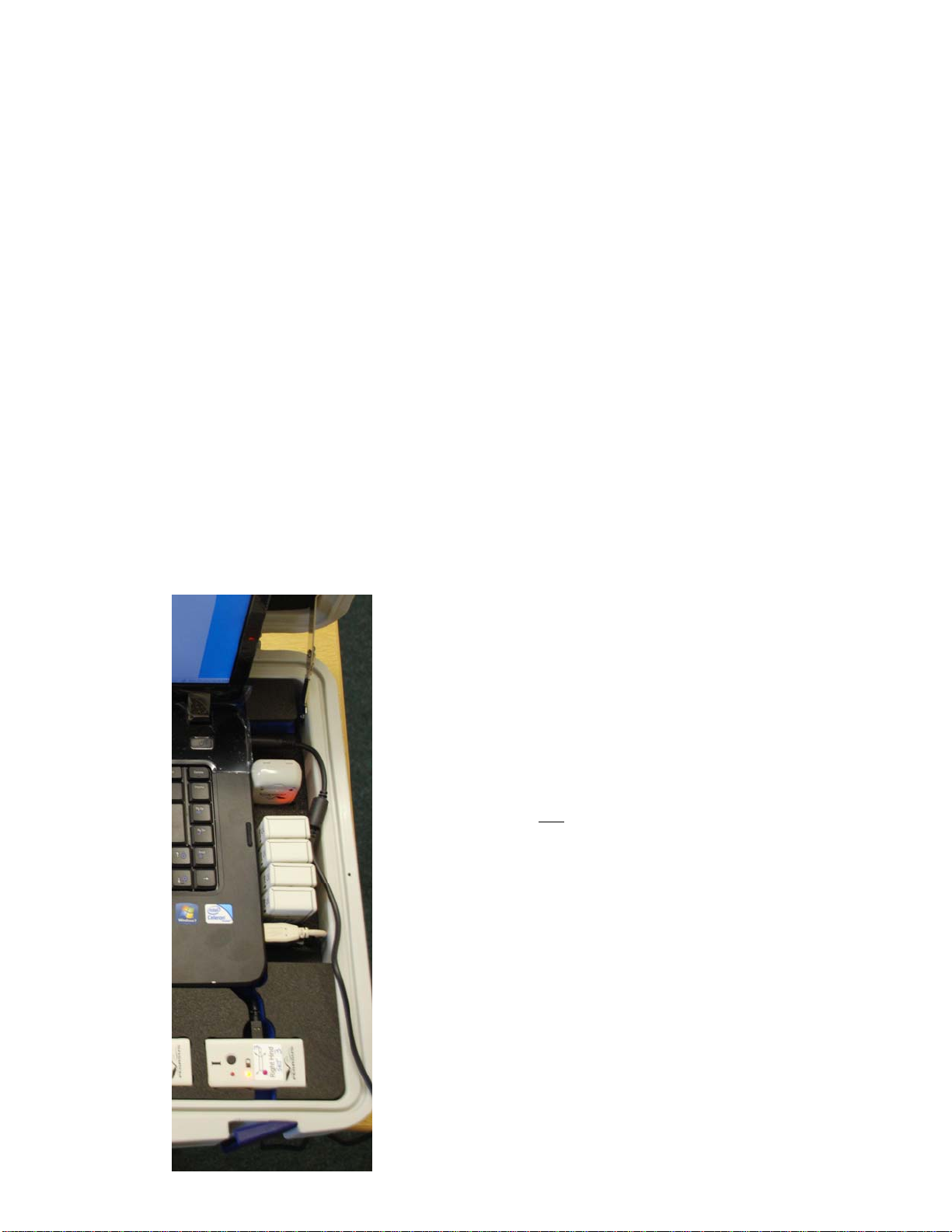
If you have purchased or upgraded to this system, the Pegasus box has been modified
to include a charging station. The power supply has been removed from the right
hand side of the box, and an insert that holds the four Pegasus-I sensors and the
Pegasus-S sensor takes its place. See photograph below. The mains power supply is
connected as normal, but is stored in the supplied rucksack. The sensors are now
considered a set, so the labels for both the Pegasus-I and Pegasus-S sensors are
annotated with Set 1 and Set 2. Ensure you keep the sensors in their designated sets
otherwise you will get the wrong result.
The second set of sensors are connected to the laptop
using two USB cables on the right side of the laptop.
This configuration allows the user to charge two
complete sets overnight and reduces the need for extra
boxes to house the sensors.
8.1. How to operate a dual Sensor
System
You can only operate one set at a time.
Remove the two USB cables from the right hand
side. You may have to lift the laptop slightly to
remove the connectors.
Now synchronise the sensor set for the front
sensors as normal, and remove all of them from
the laptop (that also includes the Pegasus-S even
if it is not to be used).
You can now reconnect the two USB connectors
on the right hand side, and synchronise the
second set.
Now carry out your trial.
Once the trial(s) have been completed carry out the
following;

Page 13 of 31
Connect the first set of sensors at the front and analyse the data.
Once complete, disconnect and remove the sensor set.
Attach the next sensor set to the front and analyse the data.
If you connect both sets of sensors you will receive error messages that too
many sensors are connected.
Once your days trials are complete, attach one set to the front, and the other set to the
charging station. Both sensor sets can now be charged overnight.
9. Performing a trial:
The trial should be carried out within an hour of setting up the sensors. If this is not
the case, the sensors should be set up again following the procedure described in the
previous section. This will ensure that all sensors remain adequately synchronised.
Take the four Pegasus-I units plus 4 brushing boots, the Pegasus S unit (where
used) and the silk (where used) to the horse.
9.1. Pegasus-S placement:
[If you are not using a Pegasus-S, because you don’t need speed, position, or stride
length, skip this section and go straight to placement of Pegasus-I units.]
Switch on the Pegasus-S wait for the blue logging LED to blink regularly and
briefly, indicating that it has acquired the satellite signals.
Place it in the silk with the blue logging LED facing upwards:
Stay in the clear and do not move indoors or the satellite fix may be lost.

Page 14 of 31
9.2. Pegasus-I placement:
[Each sensor has a label which defines on which limb it should be placed. It is
essential that each sensor is mounted in the correct location and orientation.]
Attach the brushing boots (colour and type may vary to the image shown here),
using the lower Velcro strap only. Make sure the strap is tight and secure or
the results will be degraded:
Take a Pegasus-I and press the button once, checking that the unit is logging data
(green LED blinking).
Place it in a clear polythene bag to keep out dust and moisture.

Page 15 of 31
Fit the Pegasus-I into the appropriate brushing boot pocket, taking careful note of
the label indicating its position on the animal. The unit should be upright (not
inverted), and the LEDs should face outwards:

Page 16 of 31
Once in the pocket the second Velcro strap should then be fastened. Again, make
sure the strap is tight and secure:
Repeat these steps for the three remaining Pegasus-I sensors.
The horse should now be exercised as required for the trial.
Once the trial is complete, remove the brushing boots from the horse.
Remove the Pegasus-I sensors from the pockets.

Page 17 of 31
Check that only the green status LED is flashing (the presence of amber indicates
a stuck sensor or a loose memory card: if this happens, refer to the Sensors
Manual).
Stop each Pegasus-I logging by pressing the button: no LEDs should be lit.
Remove the silk.
Retrieve Pegasus-S from the pocket and switch it off.
10.Retrieving and analysing data from the trial:
The system is designed to make the analysis of data immediately after a trial as quick
and easy as possible.
Return to the notebook PC and open Poseidon..
Select Tools from the left-hand menu: the following three options then appear at
the top of the screen: Done; Analyse Gait; Analyse Gait with Speed and
Review.
Below this there is a section where the trial details are entered.
Enter the name of the horse, rider and location: these will appear on the graph and
report.
We strongly advise that you save the raw data files. Should you upgrade to the
cannon angle software, you will be able to run that software on these files.
If you also wish to save the raw data, click on the square alongside the line: ‘Check
here if you wish to save the raw data from the units as files on the computer.’ You
will then be asked where to store the data. See screen shot below. If you look at the
screen shot, we have already tested three horses called A-tech, Billy and Broughton.
It is best to save the data into its own folder. So for example if we have just done a
trial on a horse called Saracen, we would create the folder as follows. The folder
where the computer is suggesting is ‘etb/Documents/PoseidonData’ See the top line
of the window below. In all folder operations, this line informs you of where you are
looking.

Page 18 of 31
In the top right hand of the window you will see the button Create Folder. Click on
this and the list of folders will drop down and a blue band will appear with the
following text in it ‘Type name of new folder’, see below.

Page 19 of 31
Place the cursor in the box and type the name, in this example it will be ‘Saracen’
Do not press the ‘Open’ button in the bottom right corner.
You press the enter key on the keyboard, or click in the blue area next to the Saracen
folder name on the right. This is the strange part of the process which is out of ETB’s
control, it is the operating system. You will soon get use to this.
Ok, now either click in the blue area on the right next to the Saracen file name, or
press the return key and you will get the window below.

Page 20 of 31
You can now see that we are at the etb/documents/PoseidonData/Saracen folder. Now
you can press open and the data from the sensors will be saved in this folder.
. 10.1. Retrieving and analysing data from the trial with GPS
speed data:
Connect the four Pegasus-I units (the order in which the Pegasus-I units are
placed in the recessed foam within the case does not matter).
Connect the Pegasus-S and switch on.
Click on Analyse Gait with Speed. A progress bar is then displayed, together
with information as to the current stage in the process which may take several
minutes, depending upon the duration of the trial. The stages are: collecting data
from the units, processing the data, and calculating the results.
Once the analysis has been completed two graphs are shown on the screen. The
top one showing gait types automatically generated and the stride duration, the
lower one showing the GPS plot of where you rode.
Switch off Pegasus-S.
This manual suits for next models
2
Table of contents
Popular Farm Equipment manuals by other brands

Schaffert
Schaffert Rebounder Mounting instructions

Stocks AG
Stocks AG Fan Jet Pro Plus 65 Original Operating Manual and parts list

Cumberland
Cumberland Integra Feed-Link Installation and operation manual

BROWN
BROWN BDHP-1250 Owner's/operator's manual

Molon
Molon BCS operating instructions

Vaderstad
Vaderstad Rapid Series instructions


