ETC Installation Guide
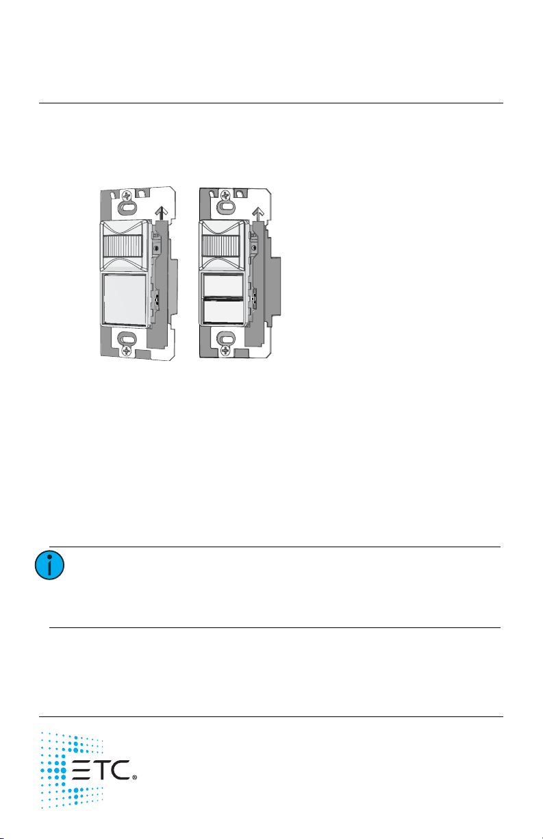
Switch-mount Occupancy Sensor
Echo Dual Tech Switch-mount Occupancy Sensor Page 4 of 20 ETC
Installation
Installation should follow all local codes and standard electrical practices.
The switch box should be installed plumb and square for best results. Ensure
that the switch box is clean and free of obstructions and that all wiring is
installed correctly.
Switch-mount Occupancy Sensors ship with a termination kit for use with
Belden 8471 (or equivalent wire), and include power and ground wire
pigtails, spacers, and all required wire termination connectors for installation.
Connect the Wiring
1: Pull all required wiring (data+, data-) into the installed switch box. As
needed, pull an additional ESD ground wire (required when the sensor
wiring is not installed in grounded metal conduit).
2: Connect sensor ESD ground wire pigtail.
a: Strip 3/8” (9-10 mm) of insulation from the ends of the sensor
ground wire pigtail, provided in the termination kit, and the
incoming ground wire.
b: Use one WAGO connector, provided in the termination kit, to
connect the sensor ESD ground pigtail and the incoming ground.
For sensors using grounded metal conduit, connect the ground
pigtail to the metal switch box ground location.
c: Install the ESD ground wire pigtail Faston connector to the spade
terminal on the sensor electronics.
3: Terminate and connect EchoConnect wires. EchoConnect is topology
free, you may install the wires in any combination of bus, star, loop, or
home-run.
a: Strip 3/8” (9-10 mm) from the ends of each power pigtail wire,
provided in the termination kit, and the installed control wires.
b: Use the provided WAGO connectors to connect the power pigtail
wires and the installed Belden 8471 control wires. One WAGO
should be used for the white wire pair (data +) and one for the
black wire pair (data -). For each wire, open the terminal levers on
the WAGO connector and insert the installed Belden 8471 wire
and the lead from the power pigtail into the terminals, then close
the levers.
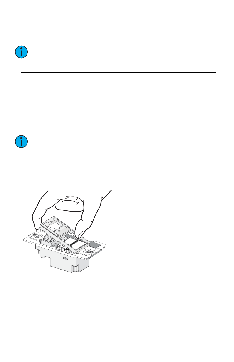
c: Install the two pin connector from the power pigtail to the mating
receptacle on the sensor electronics.
Note:
NEC Class 2 product to be wired in accordance to NEC
Article 725 and local jurisdiction requirements.