Echoflex Installation Guide
Dual Tech Wall-mount Vacancy Sensor
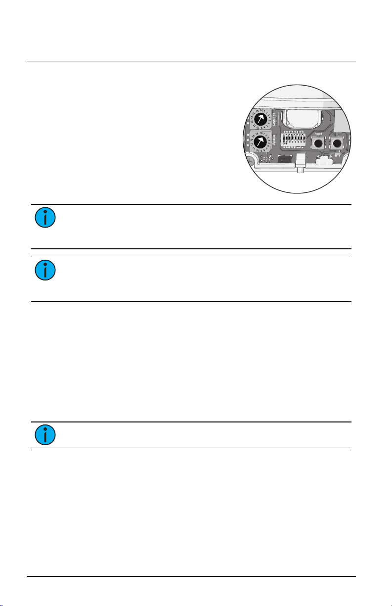
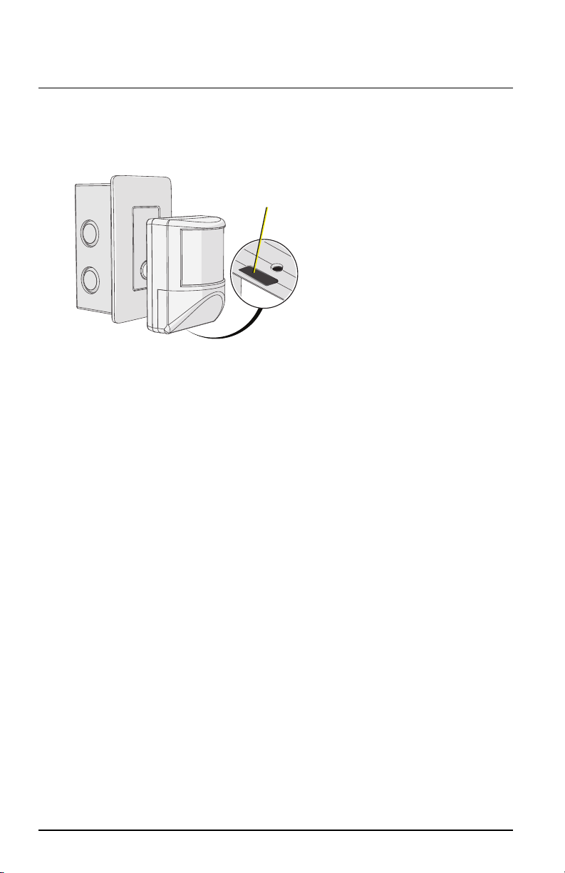
DIP Switches
DIP switches on the sensor electronics provide for additional
configuration options including Use Custom Config, Vacancy Timeout,
Enable/Disable detection LEDs, PIR Only Mode, and the ability to restore
the sensor to its factory defaults.
Switch # Use
1Unused (leave Off)
2Enable/Disable Custom Config Mode
• When “Custom Config” is set to On (the default
setting), all other local DIP switch settings are
ignored. Instead, the settings made by the
ElahoAccess App are used.
• When “Custom Config” is set to Off, also known as
Basic configuration mode, the local DIP switch
settings for Vacancy Timeout, Enable PIR LED, and
dual technology features are used. See
Configuration
on page 8
.
3 and 4 Vacancy Timeout
• 5 min = Switches 3 and 4 are Off
• 15 min = Switch 3 is Off and Switch 4 is On (default)
• 30 min = Switch 3 is On and Switch 4 is Off
• Auto = Both switches are On
5Detection LEDs
• When set to On (the default setting), the occupancy
detection LEDs illuminate when movement is
detected.
• When set to Off, the occupancy detection LEDs are
disabled unless the unit is in Walk Test mode.
6PIR Only Mode
• When set to On, acoustic detection technology is
disabled for the sensor.
• When set to Off (the default setting), both PIR and
acoustic detection technologies are used by the
sensor.
7Unused (leave Off)
8Restore to Defaults at boot
• When set to On and power is cycled to the sensor,
the unit restores to its factory default settings.
• Off is the default setting.
Dual Tech Wall-mount Vacancy Sensor Page 7 of 12 Echoflex