ETC Unison Paradigm User manual

ETC Installation Guide
Unison Paradigm®Dual Tech
Wall-mount Occupancy Sensor
Corporate Headquarters
Middleton, Wisconsin, USA
Tel +608 831 4116
Service (Americas)
London, UK
Tel +44 (0)20 8896 1000
Service: (UK)
service@etceurope.com
Rome, IT
Tel +39 (06) 32 111 683
Holzkirchen, DE
Tel +49 (80 24) 47 00-0
Hong Kong
Tel +852 2799 1220
Web:
etcconnect.com
© 2017 Electronic Theatre Controls, Inc.
Product information and
specifications subject to change.
ETC intends this document to be provided in its entirety.
7184M2162
Rev A
Released 2017-05
Overview
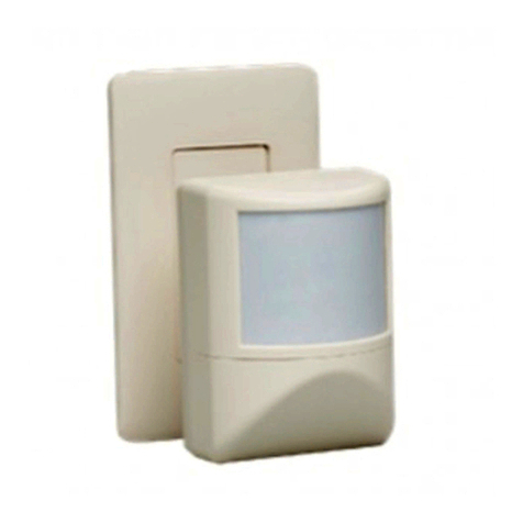
The Paradigm Dual Tech Wall-mount Occupancy Sensor uses passive infrared
(PIR) technology and acoustic detection to provide reliable occupancy and
vacancy sensing for lighting control.
The wall-mount unit offers up to 140 degree field of detection with
optimized lens options to accommodate wide or narrow angle spaces. The
sensor is available in white, black, or cream finish.
Configuration
The Paradigm Architectural Control Processor (P-ACP) to which this Dual Tech
Wall-mount Occupancy Sensor is connected must learn, or be told, the
station hardware address (a.k.a. neuron ID). This ID (as labeled on the station)
can be manually entered into the configuration using LightDesigner software,
or it can be identified by the connected Paradigm ACP using the “Connect
Device” menu. See
Binding the Sensor to Paradigm
on
page 5
.
Reference the Unison Paradigm Architectural Control Processor
Configuration Manual; specifically the section on Arch Setup Menu >
LonWorks Connections, or the reference Paradigm LightDesigner online help
system for related information to associate and connect the station to the
Paradigm control system.
Wall-mount - Wide angle lens - coverage
• 60 ft (18.3 m) coverage at mounting height of 7-10
ft (2.1 - 3 m)
• 140 degree field of detection
Wall-mount - Narrow angle lens - coverage
• 16ft (4.9 m) by 75 ft (22.9 m) coverage at mounting
height of 6-7 ft (1.8 - 2.1 m)
• 40 degree field of detection
Reference
Sensor Coverage
on
page 7
.

ETC Installation Guide
Dual Tech Wall-mount Occupancy Sensor
Dual Tech Wall-mount Occupancy Sensor Page 2 of 8 ETC
Prepare for Installation
Wall-mount sensors are intended for installation to a finished wall surface or
attached to a single-gang RACO switch box.
Compliance
• UL/cUL listed, complies with UL508A, UL916, and CSA C22.2
• CE compliant
For use with ETC Paradigm Control Systems, powered by Paradigm Station
Modules and/or Paradigm Station Repeater Modules.
Environment
Ambient
For indoor, commercial controls use only. The sensors operate in ambient
temperatures of -10° C to 40° C, with a maximum of 90% non-condensing
humidity.
Installation
ETC recommends paying special attention to the installation environment:
• When operating in PIR only modes, the sensor must have an
unobstructed view of the room. Do not mount behind or near tall
cabinets, shelves, hanging light fixtures, etc.
• Do not install the sensor within eight feet from an HVAC airflow duct/
vent.
• Install the sensor where it cannot easily sense movement in areas
outside of the intended space, such as hallways, glass partitions, or
adjacent rooms.
Note:
Installation should follow all local codes and standard
electrical practices.
Note:
In areas of increased noise activity, enabling PIR only
mode may allow for better occupancy detection results.
This setting is available using LightDesigner
configuration software.

ETC Installation Guide
Dual Tech Wall-mount Occupancy Sensor
Dual Tech Wall-mount Occupancy Sensor Page 3 of 8 ETC
Control Wire Specification
Wall-mount Occupancy Sensors connect to the LinkConnect station
communication bus. LinkConnect is a bidirectional protocol that uses one
pair of wires (data+ and data-) for both data and power. ETC recommends
using Belden 8471 (or approved equal) Class 2 wire. The total combined
length of a LinkConnect wire run (using Belden 8471, or equal) may not
exceed 1,640 feet (500 m) with a maximum distance of 1,312 feet (400 m)
between any two devices.
Parts and Supplies
The following parts and supplies are included with the sensor:
• mounting bracket with pre-routed LinkConnect pigtail wires
• mounting screws
• WAGO (wire termination connectors)
Installation
Installation should follow all local codes and standard electrical practices.
Note:
All control wiring should be installed and terminated by
a qualified installer and should follow standard wiring
installation practices. Leave approximately 10 inches
(254 mm) of wiring in the switch box for connection and
to allow slack for future service needs.
Note:
ETC requires that all stations be grounded. Pull an
additional 14 AWG (2.5 mm
2
) wire for grounding when
control wires are not installed in grounded metal
conduit.
Note:
NEC Class 2 product to be wired in accordance to NEC
Article 725 and local jurisdiction requirements.

ETC Installation Guide
Dual Tech Wall-mount Occupancy Sensor
Dual Tech Wall-mount Occupancy Sensor Page 4 of 8 ETC
1: Pull the Belden 8471 (or equivalent) and one 14 AWG (2.5 mm
2
)
ground wire to the mounting location (switch box or surface) and strip
each wire 3/8” (9-10 mm).
2: Connect the LinkConnect pigtail wires from the mounting bracket to
the installed wall wires.
a: Connect the data - (typically black) LinkConnect wire from
mounting bracket to the incoming LinkConnect (typically black)
wire using a WAGO wire termination connector.
b: Repeat the above steps for the data + (typically white)
LinkConnect wire and for the ESD ground wire, using a new
WAGO connector for each termination type.
3: Orient the mounting plate, with the directional arrows in the upright
position, to the mounting box and secure it in place using the two
screws provided.
4: Install the wall plate to the mounting plate.
a: Align the top of the wall plate to the mounting plate, angling the
bottom slightly.
The wall-mount sensor is provided with
a mounting bracket with pre-routed
LinkConnect pigtail wires. The sensor
can be mounted to a switch box or
finished wall surface.
b: Hook the top of the wall plate to the
tabs located on the mounting plate.
c: Swing the wall plate down, ensuring
the neck of the sensor extension and
wires feed through the opening, until
the magnets engage.
d: If the wall plate does not fully attach,
wiggle the bottom of the plate
until all of the magnets are
seated properly.

ETC Installation Guide
Dual Tech Wall-mount Occupancy Sensor
Dual Tech Wall-mount Occupancy Sensor Page 5 of 8 ETC
Power Up and Test
Power Up
All LinkConnect terminations in the system must be made before applying
power to the system. When the sensor is powered up, the PIR and acoustic
detection LEDs illuminate for one minute for calibration and warm-up.
Binding the Sensor to Paradigm
During the power up sequence, sensor configuration is not allowed and no
events are triggered, but the sensor will bind to the Paradigm Architectural
Control Processor (P-ACP) if the system was pre-configured and ready for
binding. The sensor receives all configuration properties from the connected
P-ACP after binding.
Alternatively, if the sensor doesn’t automatically bind to the P-ACP, it can be
identified by pressing the [Walk Test] button and by using the connected
Paradigm ACP “LonWorks Connections” menu. Reference the related source
documentation, either the
LightDesigner Online Help System
or the
Unison
Paradigm Architectural Control Processor Configuration Manual
, specifically
the section on Arch Setup Menu, LonWorks Connections.
Dual Technology
When both PIR and acoustic detection are used, the following logic is
followed:
• When the space is vacant, only PIR detection can switch the state to
occupied.
• When the space is occupied, both PIR and acoustic detection reset the
vacancy timeout.
a
b
c
d
5: Attach the sensor head.
a: Slide the removable cover off
the sensor head.
b: Route the three position
connector with wiring pigtail
through the sensor head.
c: Loosen the set screw on the
sensor retaining ring.
d: Slide the sensor onto the ball
socket, then tighten the set
screw until secure.
6: Connect the three position
connector to the
receptacle on the sensor
electronics.

ETC Installation Guide
Dual Tech Wall-mount Occupancy Sensor
Dual Tech Wall-mount Occupancy Sensor Page 6 of 8 ETC
• When occupancy in the space has only been triggered by acoustic
detection for 60 minutes, acoustic detection is disabled until the next
PIR detection event.
PIR (only) Detection
When acoustic detection is disabled, the following logic is used:
• When the space is vacant, only PIR detection can switch the state to
occupied.
• When the space is occupied, PIR detection resets the vacancy timeout.
Walk Test
1: Prepare the site for configuration.
a: Make certain the sensor is powered and bound to the P-ACP.
b: You will need direct access to the sensor in order to place it into
Walk Test mode.
2: Press the [Walk Test] button on the bottom of the sensor to enable the
Walk Test feature. A red (occupancy) and green (acoustic) LEDs will
begin to flash indicating Walk Test is enabled, and the vacancy timer
will be shortened to ten seconds.
3: Move throughout the space including corners and areas that may
specifically be obscured from line-of-sight to the sensor. Each time the
sensor detects movement, the lens will illuminate red. If acoustic
detection is enabled, any sound detected will illuminate the acoustic
detection LED green.
4: As needed, adjust the angle of the sensor head to obtain the detection
in the space.
Note:
Walk Test mode is available only when the sensor is
bound to a P-ACP. Attempting a walk test with an
unbound sensor causes the sensor walk test LED to blink
amber continuously, or until the sensor is bound to the
P-ACP.
[Walk Test]
button The sensor offers a Walk Test
mode, which shortens the
vacancy timer to ten seconds
and allows for simple and quick
verification of the sensor’s
coverage and range in the
installed space.
ETC Installation Guide
Dual Tech Wall-mount Occupancy Sensor
Dual Tech Wall-mount Occupancy Sensor Page 7 of 8 ETC
5: Walk Test mode automatically exits and the sensor returns to normal
operation after five minutes. You can also manually terminate by
pressing the [Walk Test] button again.
Verify Vacancy Operation
For systems that have been configured for the installed sensor to control
specific lighting circuits, Walk Test mode can also be used to verify vacancy
operation.
1: Confirm the installing technician has programmed the lighting control
system.
2: Enable Walk Test mode using the instructions provided in the previous
section (see
Walk Test
on
page 6
).
3: With Walk Test mode enabled, exit the room for 15 seconds to allow
the 10 second timer to expire.
4: Re-enter the room and confirm the configured vacancy / no occupancy
state was properly recalled.
5: Walk Test mode will automatically exit after five minutes from the time
it was enabled. To manually exit the Walk Test mode, press either of
the buttons on the sensor.
Sensor Coverage
Narrow Lens
(100ft)(100ft)
30.5m30.5m18.3m18.3m
(60ft)(60ft)
2.2m2.2m
(7ft)(7ft)
1m1m
(3ft)(3ft)
2.1m2.1m
(6.8ft)(6.8ft)
3m3m
(10ft)(10ft) 10.7m10.7m
(35ft)(35ft)
6.56°6.56°
2.5m2.5m
(8ft)(8ft)
0C
L
77°
77°
29°29°
21.5°21.5°
14°14°
5m5m
(16ft)(16ft)
5m5m
(16ft)(16ft)
2.5m2.5m
(8ft)(8ft)
Top View
Side View

ETC Installation Guide
Dual Tech Wall-mount Occupancy Sensor
Dual Tech Wall-mount Occupancy Sensor Page 8 of 8 ETC
Wide Lens
19.4°19.4°
0
5m5m
10m10m
(16ft)(16ft)
(33ft)(33ft)
5m5m
10m10m
(16ft)(16ft)
(33ft)(33ft)
15.3m15.3m
7.7 m7.7 m
4.6m4.6m
1.7m1.7m
(50ft)(50ft)(25ft)(25ft)(15ft)(15ft)(6ft)(6ft)
2.1m2.1m
(6.8ft)(6.8ft)
140°
Top View
Side View
Table of contents
Other ETC Security Sensor manuals

ETC
ETC echoflex MOS-IR A Series User manual

ETC
ETC Echo Dual Tech User manual

ETC
ETC Unison Aero UARVSS-5 User manual

ETC
ETC echoflex MOS-IR Series User manual

ETC
ETC Echo Dual Tech Wall-mount Occupancy Sensor User manual

ETC
ETC Echoflex Elaho Dual Tech Wall-mount Vacancy... User manual

ETC
ETC Echoflex Elaho User manual

ETC
ETC Echo Dual Tech User manual
Popular Security Sensor manuals by other brands

General Monitors
General Monitors IR5500 Programming guide

Siemens
Siemens Cerberus CS1140 Commissioning

Palmer
Palmer MicroCorr Digital user guide

Optex
Optex ELITE T manual

Merritt Manufacturing
Merritt Manufacturing Churchill installation instructions

Detectors Incorporated
Detectors Incorporated D371SS 3IR + UV instruction manual