ETC Unison Aero UARVSS-5 User manual

ETC Installation Guide
Unison Aero®Resonate Ceiling Mount
Occupancy / Vacancy Sensor
Resonate Ceiling Mount Sensor Page 1 of 10 Electronic Theatre Controls, Inc.
Corporate Headquarters
Middleton, Wisconsin, USA
Tel +608 831 4116
Service: (Americas)
London, UK
Tel +44 (0)20 8896 1000
Service: (UK)
Rome, IT
Tel +39 (06) 32 111 683
Service: (UK)
Holzkirchen, DE
Tel +49 (80 24) 47 00-0
Service: (DE)
techserv-hoki@etcconnect.com
Hong Kong
Tel +852 2799 1220
Service: (Asia)
Web:
www.etcconnect.com
Copyright © 2015 ETC. All Rights Reserved.
Product information and specifications subject to change
.
ETC intends this document to be provided in its entirety.
7188M2130
Rev A
Released 2015-06
Overview
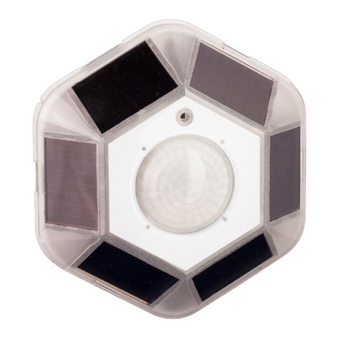
The Aero Resonate Ceiling Mount Occupancy / Vacancy Sensor is a
wireless passive Infrared (PIR) vacancy sensor that provides battery-free,
wireless control of lighting, combined with simple installation and
long-term maintenance-free reliability.
The sensor requires no wiring connections and requires no batteries,
although one can be used if needed. In normal operation, charged solar
cells provide power to the sensor.
The sensor communicates with linked Aero power controllers to
manage lighting within interior spaces. The sensor detects the
occupancy or vacancy state of the room by monitoring motion using an
integral passive infrared motion (PIR) detector.
On initial occupancy detection, the sensor broadcasts occupancy
messages to the linked controllers and the loads will turn on. The sensor
repeats the occupied message every 100 seconds until occupancy is no
longer detected, also known as vacancy. After an additional 100
seconds with no motion detected, the sensor transmits a vacancy
message and the linked controllers turn their connected loads off.
Models available
Model Description
UARVSS-5 Small room 450 feet2(41.8m2)
UARVSL-5 Large 1800 feet2(167.2m2)

ETC Installation Guide
Resonate Ceiling Mount Sensor
Resonate Ceiling Mount Sensor Page 2 of 10 Electronic Theatre Controls, Inc.
Installation
The installation location of the Resonate Ceiling Mount Occupancy /
Vacancy Sensor is important as this will directly impact both it’s
performance and the wireless messages that are shared between the
sensor and its linked power controllers.
The sensor can be installed to a flat horizontal surface using the
integrated magnets, to a wall board ceiling using screws and anchors
(not provided), to a soft ceiling tile using the provided wire adapter, or
adhered using double-sided tape or Velcro®(not provided). Reference
Mounting Location on page 4 for detailed information.
Installation Requirements
• The sensor is for indoor use only, mounted on a ceiling 8-10’ (2.4- 3m)
from the floor.
• The sensor should be installed in the room where the Aero controller is
controlling the light fixtures or circuits, but preferably not on the same
vertical wall as the linked power controllers.
• The sensor requires line-of-sight and cannot detect occupancy through
solid objects including file cabinets, furniture, or shelving units.
• The sensor can be falsely triggered by hot moving air and hot
incandescent lights, so locating the sensor at least 4’ (1.2m) from air
vents and incandescent lighting is highly recommended.
• Mount the sensor so that at least one of the solar cells is facing a light
source. The sensor will operate in low light levels, however a minimum
of 6 foot candles must be maintained for proper solar cell charging. If
the light level does not meet this requirement, it is recommended that
you install a battery. After exposure to a natural or artificial light source
for at least 2 hours, the sensor is ready to begin operation. The sensor
stores power and will function for several days in complete darkness
before requiring a solar recharge.

ETC Installation Guide
Control Series
Resonate Ceiling Mount Sensor Page 3 of 10 Electronic Theatre Controls, Inc.
Small Room Sensor
• Hand motion is detectable up to 6’ (1.8m) when mounted on an 8’
(2.4m) ceiling. For smaller offices where hand motion on a desktop is
common, locate the sensor off to one end of the desk, in line with the
desk edge or slightly behind so the PIR lens has direct line-of-sight to the
keyboard desktop area.
• The sensor is calibrated to detect body movement, but small objects will
not trigger the sensor.
• Use the included lens mask stickers to block off areas of the PIR lens
mask that may detect doorway walk-by-traffic, mitigating false
occupancy detection at the sensor.
Large Room Sensor
• Walking and large motion is detectable up to 20 feet (6.1m). Small
movements decrease as the ceiling height becomes greater than 9 feet
(2.7m). Movement perpendicular to the sensor is more easily detected.
Small Room Sensor- use for small motion detection or small rooms
0
0
8ft/2.4m
10ft / 3m
15ft/4.5m 15ft/4.5m10ft/3m 10ft/3m5ft/1.5m 5ft/1.5m
Large Room Sensor- use for large motion detection or larger rooms
0
0
8ft/2.4m
10ft / 3m
30ft/9.1m 30ft/9.1m20ft/6m 20ft/6m10ft/3m 10ft/3m

ETC Installation Guide
Resonate Ceiling Mount Sensor
Resonate Ceiling Mount Sensor Page 4 of 10 Electronic Theatre Controls, Inc.
Mounting Location
The sensor should be installed in the room where the Aero controller is
controlling the light fixtures or circuits, but preferably not on the same
vertical wall as the linked power controllers.
Consideration should be made for locating Aero controllers, switches,
and sensors based on the construction materials in the space and
furniture that may disrupt the transmissions. Installation should follow
local codes and standard practices. It is recommended that stations and
sensors be placed within 50 feet (15m) of the controller for optimal
performance.
Typical Radio Range
Material Range - typical
Line of sight 80 feet (24m) corridors
Line of sight 150 feet (46m) open halls
Plasterboard 80 feet (24m) through 3 walls
Brick 33 feet (10m) through 1 walls
FerroConcrete 33 feet (10m) through 1 wall
Ceiling 1 ceiling
Signal Loss
Material Attenuation
Wood / Plaster / Glass 0-10%
Brick / MDF 5-35%
Ferroconcrete 10-90%
Metal / Aluminum 90-100%

ETC Installation Guide
Control Series
Resonate Ceiling Mount Sensor Page 5 of 10 Electronic Theatre Controls, Inc.
Installing the Sensor
The recommended mounting location is on the ceiling.
Using Integrated Magnets
The sensor is provided with integrated magnets allowing installation to
a T-bar ceiling frame or other metallic surface by simply aligning the
back side of the sensor to the metal rail.
Using Screws
Use the appropriate screws and anchors for the mounting substrate.
Screws and anchors are not included.
Step 1: While holding the sensor in one hand, fingers on the lens
edges, insert a pencil, eraser side, through the underside
mounting keyhole and push gently, separating the cover from
the sensor.
Step 2: Align the sensor to the ceiling and mark the two mounting
keyholes.
Step 3: Pre-drill the required mounting holes and install wall anchors
(if required).
Step 4: Attach the sensor with screws (not included).
Note:
Do not reinstall the cover yet. Access to the battery and
[Link] button are required before final installation.

ETC Installation Guide
Resonate Ceiling Mount Sensor
Resonate Ceiling Mount Sensor Page 6 of 10 Electronic Theatre Controls, Inc.
Using Tape or Velcro
Use double-sided tape or Velcro (not included) to attach the Sensor to a
smooth surface.
Step 1: Attach two 1.5 inch (4cm) strips of tape or Velcro to the back
of the sensor, ensuring they do not extend beyond the edge.
Step 2: Do one of the following:
• If using double-sided tape, remove the protective film to
reveal the sticky surface.
• If using Velcro, attach the opposite Velcro material to its
mating strips and then remove the protective film to
reveal the sticky surface.
Step 3: Press the Sensor into place.
Using Soft Ceiling Tile Adapter
Use the provided soft ceiling tile adapters provided with the sensor.
Step 1: While holding the sensor in one hand, insert a pencil, eraser
side, through the underside mounting keyhole and push
gently, separating the cover from the sensor.
Step 2: Align the sensor to the ceiling and mark the two mounting
keyholes, then remove the ceiling tile from the T-bar frame.
Step 3: Re align the sensor to the marked holes, then insert the soft
ceiling tile adaptors through the pair of small holes beside
each of the keyholes on the sensors mounting plate.

ETC Installation Guide
Control Series
Resonate Ceiling Mount Sensor Page 7 of 10 Electronic Theatre Controls, Inc.
Step 4: Poke the adapter tines through the ceiling tile, then bend each
tine over in opposite directions for a secure fit.
Step 5: Replace the ceiling tile, but do not replace the cover to the
sensor yet.
Lens Masking
Lens mask stickers are provided in the packaging
for your convenience.
Step 1: As needed, peel off the lens masks to
fit the desired area to be blocked.
Step 2: Apply the mask gently to the section
of the lens exterior to block the
required area from occupancy
sensing.
Step 3: Do not replace the cover to the sensor. This will be reinstalled
later, during the final installation procedure.
Poke the adaptor tines through the ceiling tile, then bend
each tine over in opposite directions for a secure fit.

ETC Installation Guide
Resonate Ceiling Mount Sensor
Resonate Ceiling Mount Sensor Page 8 of 10 Electronic Theatre Controls, Inc.
Linking the Sensor to a Controller
This process requires the sensor to be installed with the cover removed
for access to the [Link] button. In addition, the controller or receiver to
be linked must be installed, powered, and within range of the sensor.
Step 1: Activate Learn mode on the
controller or receiver you will be
linking the sensor.
Step 2: Press the sensor [Link] button.
Step 3: Deactivate Learn mode at the
controller or receiver.
Testing and Configuring the
Sensor
Aero sensors offer multiple built-in tests allowing for testing of
operational light levels, range confirmation between the sensor and its
linked controller or receiver and walk test mode. Running tests requires
more than operational power at the sensor using the built-in solar
power. For optimal performance, install a battery to assist with the
extra power required. Alternatively, supply a charge from a handheld
light source, such as an LED flashlight, before each test to maintain
power levels.
Walk Test Mode and Setting the Sensitivity instructions are provided
here. Reference the Unison Aero 902 MHz Programming Guide for
additional configuration and test modes.
Note:
The sensor must be exposed to a good light source for at least two hours
before assigning it to a controller or receiver. A battery (CR1632, 3V coin
battery) may be used to assist when proper charge is not possible.
optional
CR1632
3V
battery
SW1
+
Link

ETC Installation Guide
Control Series
Resonate Ceiling Mount Sensor Page 9 of 10 Electronic Theatre Controls, Inc.
Walk Test Mode
Walk Test mode allows an installer to verify the sensor can monitor and
detect motion in an area as required.
Step 1: Prepare the site for configuration.
a: The circuit you are configuring must be powered on.
b: You will need direct access to the sensor [Link] button
which is located on the bottom right side of the sensor.
Step 2: Press and hold the [Link] button for 6 seconds. A green LED,
located on the lower right corner of the solar panel, will blink.
Step 3: Press and release the [Link] button twice. A red LED will
indicate.
Step 4: Press and hold the [Link] button for 6 seconds the enter Walk
Test mode.
Step 5: Walk or wave your hand in the detection zone. The LED blinks
red when motion is detected. The test expires after 100
seconds or you may press and hold the [Link] button for 10
seconds to exit Walk Test mode.

ETC Installation Guide
Resonate Ceiling Mount Sensor
Resonate Ceiling Mount Sensor Page 10 of 10 Electronic Theatre Controls, Inc.
Setting the Sensitivity
The Resonate Ceiling Mount Occupancy / Vacancy Sensor sensitivity to
motion is configurable to low, medium or high. False occupancy states
caused by other elements can be mitigated by reducing the sensitivity
level. By default, the sensor is set to high sensitivity detection.
Step 1: Press and hold the [Link] button for 6 seconds. A green LED,
located on the bottom right corner of the solar panel, will
blink.
Step 2: Press and release the [Link] button 3 times. Both red and
amber LEDs will indicate and blink.
Step 3: Press and hold the [Link] button for 6 seconds to select
Sensitivity Adjust Mode. An LED will blink based on the current
selected setting. Reference the table below for indication:
Step 4: Press and release the [Link] button to cycle through the
available settings. Each button press will indicate with an LED
color change.
Step 5: To save the current sensitivity selection, press and hold the
[Link] button for 10 seconds. To exit without saving, wait 60
seconds, allowing the test to expire.
Sensitivity Adjust
Setting Indication
High (default) Green LED (blinking)
Medium Amber LED (blinking)
Low Red LED (blinking)
Note:
The low sensitivity setting is used as the baseline for the
lens detection ray diagrams found on page 3 through
page 5.
When equipped with 902MHz radio -
Contains FCC ID: SZV-TCM300U and contains IC: 5713A-STM300U
The enclosed device complies with Part 15 of the FCC Rules.
Operation is subject to the following two conditions:
(I.) this device may not cause harmful interference and
(ii.) this device must accept any interference received, including interference that may cause
undesired operation.
This manual suits for next models
1
Table of contents
Other ETC Security Sensor manuals

ETC
ETC Echoflex Elaho User manual

ETC
ETC echoflex MOS-IR Series User manual

ETC
ETC Echo Dual Tech Wall-mount Occupancy Sensor User manual

ETC
ETC Echo Dual Tech User manual

ETC
ETC Echo Dual Tech User manual

ETC
ETC Unison Paradigm User manual

ETC
ETC Echoflex Elaho Dual Tech Wall-mount Vacancy... User manual

ETC
ETC echoflex MOS-IR A Series User manual