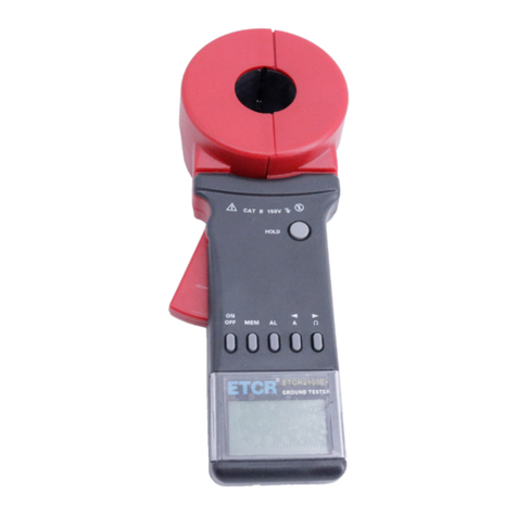
ETCR 8600 User manual


1
Content
Attention...................................................................................................2
I. Briefintroduction.................................................................................4
II. ElectricalSymbol ...............................................................................4
III. TechnicalSpecification.....................................................................4
IV. Instrument Structure.........................................................................6
V. Instrument Operation.........................................................................6
1. bootup, shutdown.........................................................................6
2. Manual/automaticswitch............................................................6
3. Switchthegearofratedoperatingcurrent....................................7
4. Reset..............................................................................................7
5. Measurement.................................................................................7
VI. ReplacingBattery.............................................................................9
VII. Accessories......................................................................................9

2
Attention
Thankyouforpurchasing ETCR8600 LeakageProtectorTester
of ourcompany.Inordertomakebetteruseof the product, please
becertain:
Toreadthisusermanual carefully.
Tocomplywiththeoperating cautionspresentedinthis
manual.
uPayspecialattention tosafetywhen usingthisinstrumentinany
case.
uObservethe textandsymbolsattachedtothefrontandrear
panelsofthe instrument.
uDon notuse theinstrumenttomeasurealinewithavoltage
higherthan250V.
uBeforemeasurement,disconnecttheloadfuse ofthe
measuredleakageprotector.
uLinterface mustconnecttothefirewire,Ninterface must
connecttotheground wire.
uTheSockettestlineoftheinstrumentiscustom-made,
forbidtouse otherplug withcordinsteadofit.
uAftermeasurement, removed thetestwirefromthe measured
wirefirst.
uIt isforbidden tousetheinstrumentwhen neitherrearcoverof
the instrument northebattercoverisinplace.
uNeverusetheinstrumentwhen theinstrumentcaseormea-
suringwireisbroken and thereforeanymetallicpartisexposed.
uDon notplacethe instrumentataenvironmentwithhightem-
perature,highhumidity,condensationand directsunshine fora
longtime
uIt isnecessarytomaintaintheinstrumentperiodicallytokeepit
clean.Donnotwipetheinstrumentbyusingcorrosivemedium
orabrasiveobject.
uPleaseobservethe correctpolaritywhen replacingthe battery.
Removethe batteryfromthe instrument ifyou expect not touse
the instrument foralongtime.
uPleasereplacethe batterywithanewone when thebattervol-
tageissolowthat theLCD displayisdim.

3
uOperation,disassemblyandmaintenanceofthe instrument
mustbecarried out onlybyaauthorized and qualified person.
uWhen thereisan instrumentfault, neveruseitbecauseconti-
nualusemayresultindanger.Inthiscase,isolatethe instru-
mentimmediatelyand delivered toan authorized agencyfor
dealingwithit.
uTheusermustfollowthe safetyinstructionsprecededby
”warningsymbolon the instrument and manual.
uTheusermuststrictlyfollowthe instructionsprecededby
”dangersymbolon the instrument and manual.

4
I. Briefintroduction
ETCR8600 LeakageProtectorTester iswell designed andman-
ufactured foronline measuringthe leakageoperatingcurrent,
leakagenon-operatingcurrent, leakageoperatingtimeofthe lea-
kageprotector;adopt128dots×64dotsdisplayed,itisconvenient
and intuitive.The rangeofleakagecurrentis0~500mA(10 gears:
15,30,50,75,100,150,200,250,300,500mA),rangeofthe lea-
kageoperatingtimeis0~999ms. It isaproduct withhighaccuracy,
small size,lightweight, exquisiteappearance,easy tocarry,isan
idealtoolforvarietyofleakageprotectorinsiteorinlaboratory
testing.
II. Electrical Symbol
Extremelydangerous!The operatorsmustkeeptothe
safetyrulesstrictly,otherwise,electricshock will resultin
deathorinjury.
Dangerous!The operatorsmustkeeptothe safetyrules
strictly,otherwise,electricshock will resultinwill resultin
deathorinjury.
Warning!The operatorsmustkeeptothesafetyrules
strictly,otherwise,personalinjuryorequipmentdamage
will occur.
Doubleinsulation.
Alternatingcurrent (AC).
Direct current (DC).
III. Technical Specification
Function Measurementofleakageoperatingcurrent,
leakagenon-operatingcurrent, leakageoper-
atingtimeofthe leakageprotector.
PowerSupply
DC6Valkaline batteries(LR61.5V×4).
TestlineVol-
tage
Donot exceed AC250V.
ratedvoltage AC220V.

5
Leakagecur-
rentgear
15,30,50,75,100,150,200,250,300,
500mA.
rangeofthe
leakageoper-
ating time
0~999ms.
accuracyof
theleakage
ope
r
ating time
±0.5%.
accuracyof
thecurrentfor
eachgear
±1.0%.
Fail-
ureinformatio
n
When the LCD display fault,itmaybethe
measured rated operatingcurrentgearistoo
small orthe leakageprotectorhassomefaults.
lengthofthe
testline
1.8m.
Testmode Manuallyorautomatically.
Display Mode
LCD: 128dots×64dots.
Dimension 170mm×75mm×30mm.
Weight 290g(includingthe batteries);
Totalweight: 350g(includingthe packing).
LCD Dimen-
sio
n
Displayfield: 44mm×27mm.
batteryvoltage
ALow-Batterysymbolisdisplayed and the
usershouldreplacethebatterywithanewone
when the batteryvoltagedropsto4.8V.Inthis
case, themeasured valuesarestill accurate.
Working Cur-
rent
40mAMax.
Working Hu-
m
i
ture
-10 -40 , below80%rh.
StorageHu-
m
i
ture
-10 -60 , below70%rh.
Insulating
Strength
≥100MΩ,AC2kV/rms(between thealloyofthe
clampand the housing).
Applicable IEC1010-1,IEC1010-2-032,Pollutiondegree

6
safetyrules 2, CATIII(600V)IEC61326(EMCstandard).
IV. InstrumentStructure
1. N interface(connect groundwire)
2. L interface(connect firewire)
3. LCD
4.AT: autokey
5. RANGE+ key(gearup)
6. MT: manualkey
7. RANGE- key(geardown)
8. RESET: reset key
9. POWER: (boot up, shutdown)
10. Crocodilecliptest line
11. Probetest line
12. Socket testline
V. InstrumentOperation
1. bootup,shutdown
Bootupthe instrumentbypressingthe POWER key.The LCD will
lightup.Ifthe LCD displayisdim,the batteryvoltagemaybelow.If
so,replacethebatterywithanewone.Press the POWER key
againtoshutdownthe instrument. Thisinstrumentwillbeshut-
downautomaticallyafterstarting5minutes.
2. Manual / automatic switch
Thisinstrumenthasthe manual(MT)and (AT)automatictest
mode.Press MT and AT keytoswitchtomanualorautomatic
mode.Afterbootup,itisdefaulttothemanual(MT)testmode.In
the manualmode,thetopleftcornerofthe LCD shows MT symbol,
inthe automaticmode,thetopleftcornerofthe LCD shows MT
symbol.
Inthe automaticmode,startthemeasurementfromthe lowest
gear15mArated operatingcurrent. Ifthe leakageprotectordoes
nottrip,theinstrumentwill increaseagearautomaticallyafter2
seconds.If the leakageprotectoralsodoesnottrip,the instrument

7
will increaseagearautomaticallyagainafter2seconds,until the
tripbreaking.Atthistime,the displayed gearon the button of LCD
screen istheactualleakageoperatingcurrent value,thedisplayed
timeisthe leakageoperatingtime.
3. Switchthegearofrated operatingcurrent
The rated operatingcurrentofthe instrumentfrom0to500mA
weredivided intoten gears:15mA,30mA,50mA,75mA,100mA,
150mA,200mA,250mA,300mA,500mA.Press RANGE- or
RANGE+ toswitchthe gears.Onthe bottomofthe LCD indicates
the currentgear.Afterbootup,itisdefaulttothe lowestgear
(15mA)tostart test.
4. Reset
Aftereachtest, press the RESET keytoreset, the leakageoper-
atingtimewill bezeroclearing, then can betested again.
5. Measurement
Electricshock,dangerous!Theinstrumentcanbe
operatedonlybythetrainedand authorizedperson.
Theoperatorsmustkeeptothesafetyrules strictly,
otherwise,electricshock will resultinpersonalinjury
ordam
agetotheequipment.
Don notuse theinstrumenttomeasurethelineswith
avoltageofhigherthan250V.Otherwise,electric
shock will resultinpersonalinjuryordamagetothe
equipment.
Linterface mustconnecttothefirewireofthemeas-
uredleakageprotector,Ninterface mustconnectto
thegroundwireofthemeasuredleakageprotector.
Otherwise,electricshock will resultindamagetothe
equi
p
ment.
TheSockettestlineoftheinstrumentiscus-
tom-made,theredplugconnecttothefirewire,the
black plug connecttotheground wire.Forbidtouse
otherplug withcordinsteadofit.Otherwise,electric
shock will resultinpersonalinjuryordamagetothe
equipment.

8
Beforemeasurement, disconnectthe load fuseofthe measured
leakageprotectortoavoiddamagetotheloadequipment. Then
check thenameplateratingofthemeasured leakageprotector,
Accordingtothe nameplaterating todetermine the current
gear.(Generally,forthe indoortypesinglephasetwo-wiremode
leakageprotector,the ratedoperatingcurrentis30mA,the rated
non-operatingcurrentis15mA,Thebreakduration ≤0.1s,thatis
≤100ms).
Bootup,selectthetestmode and thegearoftherated leakage
operatingcurrent, itisdefaulttothemanual(MT)testmode,The
connectionasshownbelow:
Connection1: one endofblack crocodilecliptest lineinsert tothe
black Ninterfaceofthe instrument, the otherend (crocodileclip)
cliptothe groundingpileofthe leakageprotector;one endofred
probetestline inserttothe red Linterfaceofthe instrument, the
otherend(probe)touchthe firewireofthe leakageprotector’s
output endtomeasurement.
Connection 2:the black plugofthe dedicated sockettestline in-
sertintothe Ninterfaceofthe instrument, thered pluginsertinto
the Linterfaceofthe instrument, the three-pinpluginsertintoor
touchthe socket tomeasurement.
Atthistime,ifthe performanceofthe leakageprotectorisnormal,it
will tripbreaking,the breakingtimedisplayed intheLCD screen,
suchas075ms.Ifthe leakageprotectordoesnottrip, fault failure
information will displayintheLCD,itmaybethemeasuredrated
operatingcurrentgearistoo small orthe leakageprotectorhas
somefaults.Press the RESET keytoreset, then can betested
again.

9
VI. Replacing Battery
Toavoidelectricshock,whenreplacing thebatte-
ries,thetestlinemustbepulledaway fromthein-
strument,and do notconnectwiththemeasured
wire.
Observethecorrectbatterypolarity,otherwise,the
i
n
strumentwill bedamaged.
Replace thebatterywithanewoneas soon as
p
ossiblewhenthebatteryvoltageislow.
Donotmixtheoldand newbatterytogether.
1. When the batteryvoltagedropsto4.8V,a symbolwill be
displayed on theinstrument, indicatingthe batteryvoltageislow.
Replacethe batteryimmediately.
2. Press the POWER keytoshutdownthe instrument. Aftercon-
firmingthatthe instrumenthasbeen shutdownf,open the battery
coverand replacewithanewbatteryrecommended bythe manu-
facturer.Payspecialattentiontothecorrectbatterypolarity.Re-
placethe batterycover,bootupthe instrumentand confirmthatthe
instrumentcanoperateproperly.(asshowninthe followingfig-
ures).
VII. Accessories
Tester 1PCS
Shoulderbag 1 PCS
Probetest line 1PCS

10
Crocodilecliptest line 1PCS
Socket testline 1PCS
Packingbox 1PCS
Alkaline drybattery(AAA1.5V) 4PCS
Usermanual,Warrantycard,Qualitycertificate 1 Copy
Table of contents
Other ETCR Test Equipment manuals