ete 90025 User manual

CERTI-CRIMP*
Hand Tool Ratchet
Tool Number
Marking
Crimp
Type
Insulation Crimp
Adjustment Pins
Back of Tool
(Wire Side)
Wire Size
Marking
Terminal
Type
Tool Color
Code
©2011 Tyco Electronics Corporation, a TE Connectivity Ltd. Company
All Rights Reserved
*Trademark
TE Connectivity, TE connectivity (logo), and TE (logo) are trademarks. Other logos, product and/or Company names may be trademarks of their respective owners.
1of 5
Instruction Sheet
TOOLING ASSISTANCE CENTER
1-800-722-1111
PRODUCT INFORMATION
1-800-522-6752
This controlled document is subject to change.
For latest revision and Regional Customer Service,
visit our website at www.te.com LOC B
408-1809
Hand Crimping Tools 90025 and 90026 28 SEP 11 Rev B
PROPER USE GUIDELINES
Cumulative Trauma Disorders can result from the prolonged use of manually powered hand tools. Hand tools are intended for occasional use
and low volume applications. A wide selection of powered application equipment for extended-use, production operations is available.
Figure 1
1. INTRODUCTION
Hand Crimping Tools 90025 and 90026 (see Figure 1)
are designed to crimp the PIDG* Taper Pin Terminals
listed in Figure 2. Read these instructions thoroughly
before using the tools.
NOTE
i
Dimensions on this sheet are in millimeters [with
inches in brackets].
Reasons for reissue are provided in Section 7,
REVISION SUMMARY.
2. DESCRIPTION
Refer to Figure 1 and Figure 3.
The FRONT of the tool has the "AMP" marking on the
link. The BACK of the tool (wire side), into which the
wire is inserted, has the tool number marked on the
handle and the crimp type, wire size, and type of
terminal the tool can crimp ("PIDG") marked on the
link.
Each tool features two crimping jaws, a locator, two
insulation crimp adjustment pins, color-coded tool
handles, and a CERTI-CRIMP tool ratchet.
Each terminal features a color-coded sleeve which
matches the color coded tool handle marking of the
applicable crimping tool. The locator aids in
positioning the terminal between the crimping jaws.
The insulation crimp adjustment pins are used to
regulate the crimp height of the terminal insulation
barrel. The ratchet assures full crimping of the
terminal. Once engaged, the ratchet will not release
until the tool handles have been FULLY closed.
CAUTION
!
The crimping jaws bottom before the ratchet
releases. This is a design feature that assures
maximum electrical and tensile performance of the
crimp. Do NOT re-adjust the ratchet.
3. CRIMPING PROCEDURE
Refer to the table in Figure 2 and check the selected
wire, terminal, and crimping tool for compatibility.
Wire size and insulation diameter must be within the
specified range for the terminal. Strip the wire to the
length indicated - do NOT cut or nick the wire strands.
The hand tool must be the one designed for crimping
the wire and terminal.

WIRE TERMINAL HAND TOOL
SIZE
(AWG) INSULATION
DIAMETER STRIP
LENGTH PART
NO. COLOR PART
NO. HANDLE
COLOR
24 to 22 1.02 to 2.03 [.040
to .080] 5.54 [.218] 66071 Yellow 90026 2 Yellow
20 to 18 1.52 to 2.54 [.060
to .100] 6.73 [.265] 66072 White 90025 1 White and
1 Black
16 2.03 to 2.92 [.080
to .115] 6.73 [.265] 66073 Black 90025 1 White and
1 Black
Taper Pin
Color-Coded Sleeve
Wire Strip Length
408-1809
2of 5
Rev B
Figure 2
Refer to Figure 3 and proceed as follows:
1. Hold tool so BACK (wire side) faces you.
2. Make sure ratchet is released - squeeze tool
handles together and allow them to open FULLY.
3. Slide terminal tip through hole in locator until
terminal shoulder butts against locator.
4. Hold terminal in this position and squeeze tool
handles together just enough so crimping jaws hold
terminal in place. Do NOT deform insulation barrel
or wire barrel.
5. Insert a properly stripped wire into terminal wire
barrel until it bottoms.
6. Holding wire in place, squeeze tool handles
together until ratchet releases.
7. Allow tool handles to open FULLY and remove
crimped terminal from tool.
Stripped Wire
Wire Size
Back of Tool
(Wire Side)
Terminal Tip
Terminal
Shoulder
Terminal
Locator
Wire Barrel
Figure 3

408-1809
3of 5
Rev B
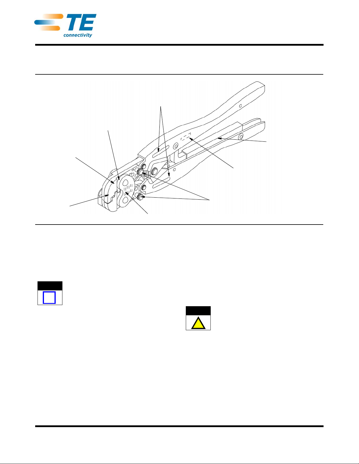
4. INSULATION CRIMP ADJUSTMENT
The insulation barrel crimp height is regulated by
placing the insulation crimp adjustment pins in one of
three positions: (1) small, (2) medium, or (3) large.
Determine the proper insulation crimp setting as
follows:
1. Place adjustment pins in No. 3 position. Insert
terminal into tool according to Section 3, CRIMPING
PROCEDURE, Steps 1 through 4.
2. Insert an UNSTRIPPED wire into terminal
insulation barrel. Crimp terminal and remove from
tool.
3. Check insulation crimp by bending wire back and
forth one time. If wire pulls out, place adjustment
pins in next smaller position and repeat these
procedures. Crimp should hold wire insulation firmly
without cutting into it.
5. MAINTENANCE AND INSPECTION PROCEDURE
The company recommends that a maintenance and
inspection program be performed periodically to
ensure dependable and uniform terminations.
Frequency of inspection depends on:
•The care, amount of use, and handling of the hand
tool.
•Abnormal amounts of dust and dirt.
•The degree of operator skill.
•Your own established standards.
The hand tool is inspected before being shipped;
however, TE recommends that the tool be inspected
immediately upon arrival to ensure that the tool has
not been damaged during shipment. Due to the
precision design, it is important that no parts of these
tools be interchanged except those replacement parts
listed in Figure 5.
5.1. Daily Maintenance
1. The hand tools should be immersed (handles
partially closed) in a reliable commercial degreasing
compound to remove accumulated dirt, grease, and
foreign matter. When degreasing compound is not
available, tool may be wiped clean with a soft, lint-
free cloth. Do NOT use hard or abrasive objects that
could damage the tool.
2. Make certain that the retaining pins are in place
and that they are secured with retaining rings.
3. All pins, pivot points, and bearing surfaces should
be protected with a THIN coat of any good SAE† 20
motor oil. Do not oil excessively.
° SAE is the Society of Automotive Enginners.
4. When the tool is not in use, keep handles closed
to prevent objects from becoming lodged in the
crimping jaws. Store the tool in a clean, dry area.
5.2. Periodic Inspection
A. Lubrication
Lubricate all pins, pivot points, and bearing surfaces
with SAE 20 motor oil as follows:
— Tools used in daily production - lubricate daily
—Tools used daily (occasional) - lubricate weekly
— Tools used weekly - lubricate monthly
Wipe excess oil from tool, particularly from crimping
area. Oil transferred from the crimping area onto
certain terminations may affect the electrical
characteristics of an application.
B. Visual Inspection
1. Close tool handles until ratchet releases and then
allow them to open freely. If they do not open
quickly and fully, the spring is defective and must be
replaced. See Section 6, REPLACEMENT AND
REPAIR.
2. Inspect head assembly for worn, cracked, or
broken jaws. If damage is evident, return the tool to
AMP for evaluation and repair. See Section 6,
REPLACEMENT AND REPAIR.
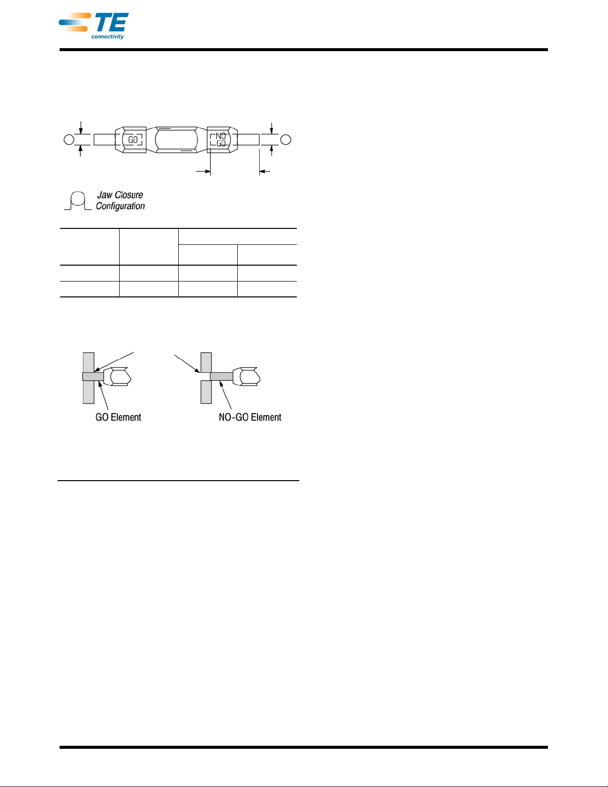
C. Gaging The Crimping Chamber
This inspection requires the use of a plug gage
conforming to the dimensions provided in Figure 4. TE
does not manufacture or market these gages. To gage
the crimping chamber, proceed as follows:
1. Remove traces of oil or dirt from the crimping
chambers and plug gage.
2. Close tool handles until jaws are bottomed, and
hold in this position. Do not force beyond initial
contact.
3. Carefully insert GO element into the crimping
chamber; do not force it. The GO element must
pass completely through the crimping chamber. See
Figure 4.
4. In the same manner, try to insert NO-GO element
into the same crimping chamber. The NO-GO
element may begin entry, but may not pass through
the crimping chamber. See Figure 4.
If crimping chambers conform to gage inspection, the
tool is considered dimensionally correct, and should
be lubricated with a THIN coat of any good SAE 20
motor oil. If not, refer to Section 6, REPLACEMENT
AND REPAIR for customer repair service.

Suggested Plug Gage Design
GO
Diameter NO-GO
Diameter
19.05 [.750]
Min Typ
TOOL
NO. CRIMPING
CHAMBER
MARKING
GAGE ELEMENT DIAMETER
GO NO-GO
90025 20-16 2.16 [.085] 2.31 [.091]
90026 24-22 1.600 [.063] 1.75 [.069]
Inspection of the Crimping Chamber
Crimping
Chamber
GO element must
pass completely
through the crimping
chamber.
NO-GOelementmayenter
partially,butmustnotpass
completely through the
crimping chamber.
408-1809
4of 5
Rev B
Figure 4
D. Ratchet Inspection
Obtain a 0.025 [.001] shim that is suitable for checking
the clearance between the bottoming surfaces of the
crimping jaws and proceed as follows.
1. Select a terminal and a wire (maximum size) for
the tool you are using (see Figure 2).
2. Position the terminal and wire between the
crimping jaws, according to Section 3, CRIMPING
PROCEDURE (Steps 1 through 5). Holding the wire
in place, squeeze the tool handles together until the
CERTI-CRIMP ratchet releases. Hold the tool
handles in this position, maintaining just enough
pressure to keep the jaws closed.
3. Check the clearance between the bottoming
surfaces of the crimping jaws. If the clearance is
0.025 [.001] or less, the ratchet is satisfactory. If
clearance exceeds 0.025 [.001], the ratchet is out of
adjustment and must be repaired (see Section 6,
REPLACEMENT AND REPAIR).
If the tool conforms to these inspection procedures,
lubricate it with a THIN coat of any good SAE† 20
motor oil and return it to service.
6. REPLACEMENT AND REPAIR
Customer-replaceable parts are listed in Figure 5.
Parts other than those listed in Figure 5 should be
replaced by TE to ensure quality and reliability of the
tool. Order replacement parts through your TE
representative, or call 1-800-526-5142, or send a
facsimile of your purchase order to 1-717-986-7605, or
write to:
† Society of Automotive Engineers
CUSTOMER SERVICE (038-035)
TYCO ELECTRONICS CORPORATION
PO BOX 3608
HARRISBURG PA 17105-3608
For customer repair service, call 1-800-526-5136.
7. REVISION SUMMARY
Revisions to this instruction sheet include:
•Changed company name and logo

REPLACEMENT PARTS
ITEM PART NUMBERS DESCRIPTION QTY PER
TOOL
90025 90026
1 21045-3 21045-3 Ring, Retaining 4
2 1-23619-6 1-23619-6 Pin, Retaining, .187 Dia x .521 L 2
3 21045-6 21045-6 Ring, Retaining 2
4 2-23620-9 2-23620-9 Pin, Retaining, .250 Dia x .838 L 1
5 39364 39364 Spring, Handle 1
6 39207 39207 Pin, Insulation Adjustment 2
7 125083-1 125083-2 Locator 1
8 3-21016-7 3-21016-7 Screw 1
408-1809
5of 5
Rev B
Figure 5
This manual suits for next models
1
Table of contents
Other ete Tools manuals
Popular Tools manuals by other brands

DS Produkte
DS Produkte OS220 instruction manual

Jefferson
Jefferson JEFUNIPCPGR user manual

Hitachi
Hitachi G23SR - 9" Angle Grinder parts list

Milwaukee
Milwaukee M12 FPTR Operator's manual

Pattfield
Pattfield PMF-300G manual

FEDERAL PACIFIC
FEDERAL PACIFIC PSE Supplement to Inspection and Maintenance Recommendations