Jefferson JEFUNIPCPGR User manual
User Manual
v.1.1
JEFUNIPCPGR
UNIVERSAL
POWER COUPLING
GREASE GUN

2
USER MANUAL v1.1
JEFUNIPCPGR
UNIVERSAL POWER COUPLING GREASE GUN
www.jeffersontools.com
CONTENTS
Contents 2
About This Document 2
Introduction 3
Specications 3
Equipment Identication 3
Power Tool Compatibility 4
Safety Guidelines 5
Before First Use 6
Grease Loading 7
Operation 8
Maintenance 8
Troubleshooting 8
Parts List & Diagram 9
Limited Warranty Statement 10
ABOUT THIS DOCUMENT
This manual has been compiled by Jefferson Tools and is an integrated part of the product with which it's enclosed
and should be kept with it for future reference. Please read all of the information supplied in this User Manual before
operating this product.
This manual describes the purpose for which the product has been designed and contains all the necessary
information to ensure its correct and safe use. We recommend that you read the information supplied before carrying
out any maintenance or repair. By following all the general safety instructions contained in this manual you will help
to ensure operator safety and extend the potential life span of the equipment.
All photographs and drawings in this manual are supplied by Jefferson Tools to help illustrate the operation of the
product. Whilst every effort has been made to ensure accuracy of information contained in this manual our policy of
continuous improvement determines the right to make modifications without prior warning.
The information contained in this Instruction Manual is designed to assist you in the safe operation and maintenance
of the equipment. Some illustrations in this Instruction Manual may show details or attachments that differ from those
on your own model. Contact your nearest Jefferson Dealer if you are unsure about any information included in this
manual or require any additional information about the safe use, operation maintenance, or repair of this equipment.
ENVIRONMENTAL PROTECTION
Recycle any packaging and unwanted materials instead of disposing of them as waste. All tools,
accessories and packaging should be sorted, taken to a recycling centre and disposed of in
a manner which is compatible with the environment. When the product becomes completely
unserviceable, reaches the end of its working life and requires disposal, drain off any uids (if
applicable) into approved containers and dispose of the product and the uids according to local
regulations.
3
USER MANUAL v1.1
JEFUNIPCPGR
UNIVERSAL POWER COUPLING GREASE GUN
www.jeffersontools.com
INTRODUCTION
• An all-purpose grease gun coupler compatible with both electric (12V ~ 18V) and pneumatic tools.
• Working pressure is derived from the electric or air powered tool.
• Fully automatic, cycles continuous lubricating grease flow to the power tool during operation.
• Heavy duty aluminium construction supporting high working pressures between 4000-8000 psi.
• Equipped with high pressure relief safety valve for user protection and durability.
• 3-way loading: 14 oz. cartridge / bulk / dispenser.
SPECIFICATIONS
Grease capacity: 14 oz. cartridge / bulk / dispenser
Rated working pressure: 4000psi •275bar •27.5Mpa
Maximum pressure: 8000psi •552bar •55.2Mpa
Pressure relief valve: Yes (>8000psi •>552bar •>55.2Mpa)
Power tool coupling holder capacity: 1.5" - 3"
AC power tool compatibility 110 - 230V
DC power tool compatibility 12V - 18V
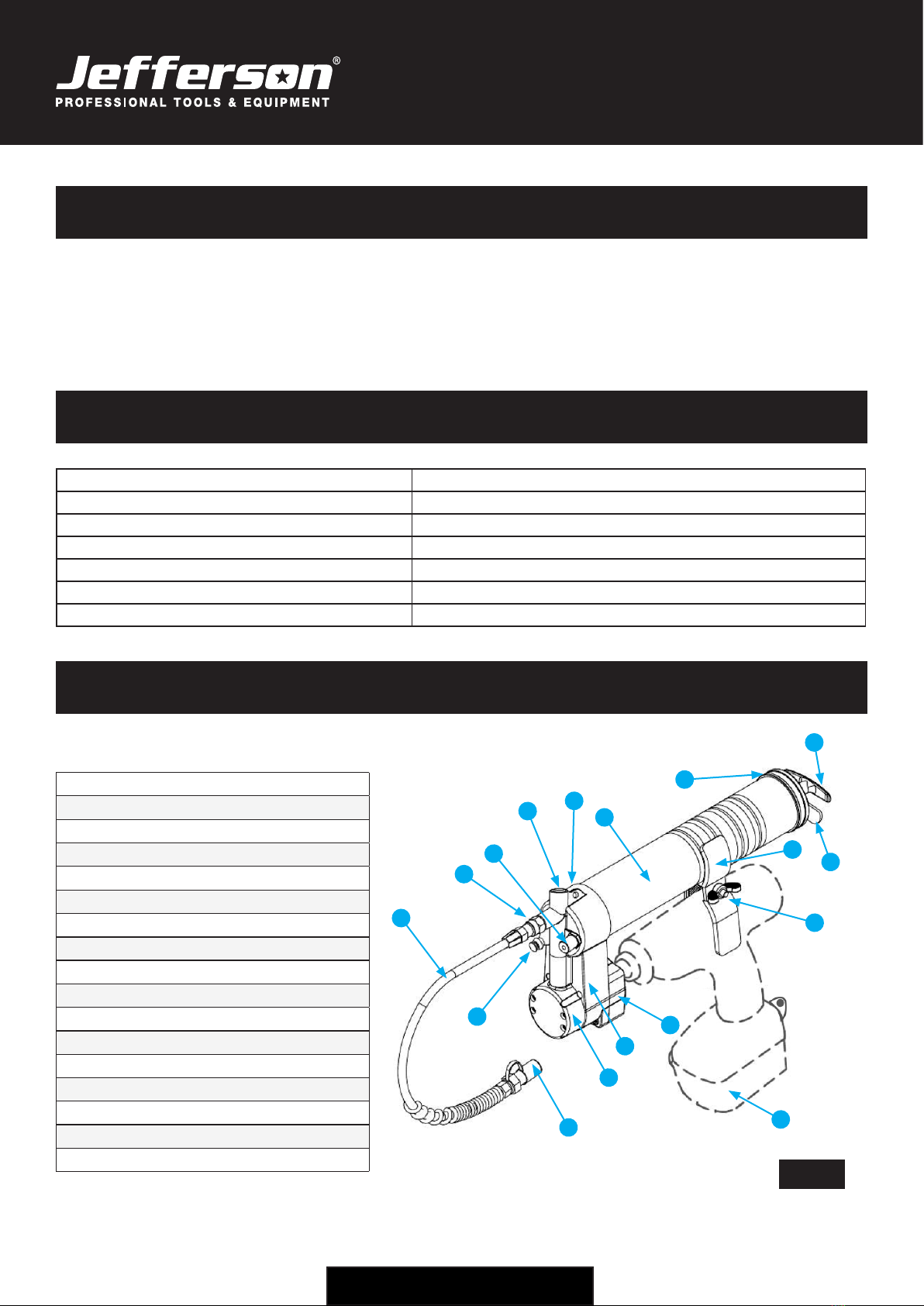
EQUIPMENT IDENTIFICATION
1. 18" High Pressure Nylon Hose
2. Grease Gun Outlet
3. Filler Plug
4. Pressure Vent Protector
4b. Gun Head
5. Container Housing
6. Container Cap
7. Plunger Handle / Assembly
8. Stopper
9. Coupling Holder
10. Buttery Locking Screw
11. (Example) Power Tool
12. Power Tool Connector
13. Gear Housing
14. Gear Cap
15. Nylon Hose Output
16. High Pressure Valve
1
16
3
45
6
7
8
9
10
12
13
11
14
15
2
Fig.1
4b
4
USER MANUAL v1.1
JEFUNIPCPGR
UNIVERSAL POWER COUPLING GREASE GUN
www.jeffersontools.com
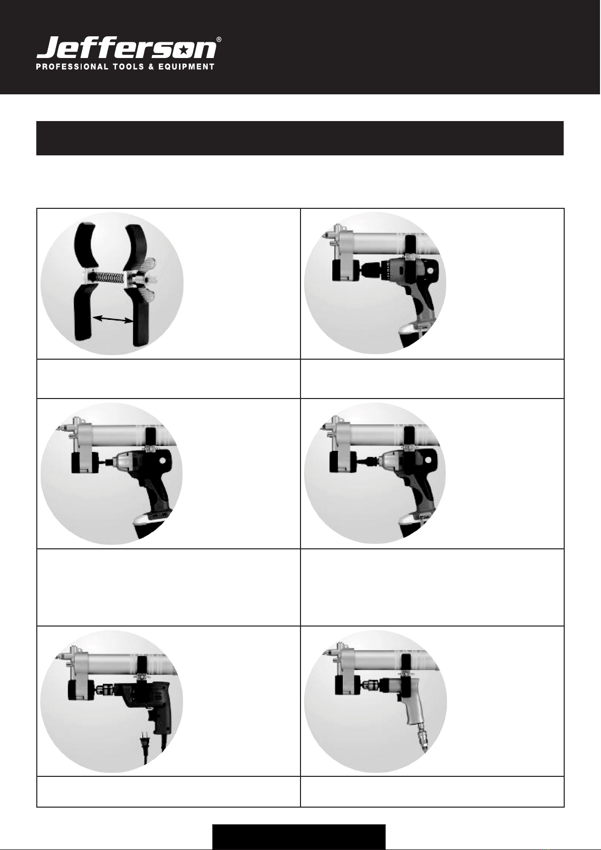
POWER TOOL COMPATIBILITY
The table below shows some typical examples of electric and air powered tools that are compatible with this
equipment. For further advice please contact Jefferson Tools.
The Coupling Holder with Butterfly Screw has an
available width of tolerance to accommodate power tools
between 1.5" - 3".
DC Battery Powered Drills 12V-18V
Keyless Chuck Type: 3/8" (9.5mm), 1/2" (13mm)
DC Battery Powered Screwdriver 12V-18V
Hex, Drive shank chuck: 1/4" (6.35mm)
DC Battery Powered Wrench 12V-18V*
Square Drive:
3/8" (9.5mm)
1/2" (13mm) *requires adaptor (not included)
AC Mains Powered Drill 110V-230V
Keyed Chuck Type: 3/8" (9.5mm), 1/2" (13mm)
Air Powered / Pneumatic Drill
Keyed Chuck Type: 3/8" (9.5mm), 1/2" (13mm)

5
USER MANUAL v1.1
JEFUNIPCPGR
UNIVERSAL POWER COUPLING GREASE GUN
www.jeffersontools.com
SAFETY GUIDELINES
Please read and ensure that you understand all of the operating instructions, safety
precautions and warnings in this Instruction Manual before operating or maintaining this
equipment. An accident can often be avoided by recognizing a potentially hazardous
situation before it occurs, and by observing the appropriate safety procedures. Never use
this equipment or modify it in any way that has not been specically recommended by the
manufacturer. Contact a qualied electrician for advice on any issues relating to electrical
safety in your working environment.
GENERAL EQUIPMENT SAFETY
• Inspect the grease gun and the power tool for damage and ensure all connections are secure before use. Do not
use the equipment if damage is detected.
• Ensure the work area is clean, uncluttered and well lit. Do not operate power tools in explosive atmospheres
including ammable liquids, gas or dust which can be ignited during operation.
• Do not operate power tools near children or animals or under the inuence of alcohol or medication.
• Always wear suitable protective equipment for the work being carried out.
• Read and follow all the safety precautions stated for the power tools you use with this product including all
electrical and pressurised equipment safety requirements.
• Contact Jefferson Tools for further advice on the safe use, maintenance, repair and compatible replacement
parts for this equipment.
GREASE GUN SAFETY
• Never place hands or other body parts near the outlet of the grease gun during operation.
• Always hold the grease gun by the handle.
• When working at height, follow all required safety procedures, carry out a risk assessment of the working
environment and ensure there is no risk of people moving below the work area.
• Always suitable protective equipment including eye protection for the work being undertaken.
• Ensure all connections between the grease supply and the power tool are secure before operation.
• Pressurised systems are only as strong as their weakest component. Never exceed the maximum working
pressure of the grease gun or the power tool.
• Check that the nylon hose is free from damage and securely connected before use. Do not hold the hose during
operation.
• Ensure that the grease gun is kept clean and well maintained to ensure safe operation and equipment durability.
• Store in a clean, dry environment out of reach of children.
WARNING:
No responsibility is accepted for incorrect use of this equipment. Incorrect use can result in damage to the equipment
and danger to the user. Warranty will be void in the event of incorrect use. The warnings, cautions and instructions
discussed in this instruction manual cannot cover all possible conditions and situations that may occur. It must be
understood by the operator that common sense and caution are factors which cannot be built into this product, but must
be supplied by the operator.
6
USER MANUAL v1.1
JEFUNIPCPGR
UNIVERSAL POWER COUPLING GREASE GUN
www.jeffersontools.com
ELECTRICAL SAFETY FOR POWER TOOLS
Ensure that you check the equipment thoroughly to ensure it is safe and t for purpose before each
use. It is important that you inspect all plugs, sockets, power cables and electrical ttings for wear
and damage and repair or replace any defective components. The risk of electric shock can be
minimised by the correct use of the appropriate electrical safety devices.
• We recommend that you t a Residual Current Circuit Breaker (RCCB) in the main distribution board and that a
Residual Current Device (RCD) is used when operating this equipment.
• The Electricity at Work Act 1989 includes legislation that places legal implications on employers to ensure
the safety of electrical devices in the workplace. The regulations dictate that all portable equipment must be
inspected regularly and tested to ensure that it is safe for use. 'Portable equipment' means any electrical item
that can be moved and this is often referred to as Portable Appliance Testing (PAT). PAT testing should be carried
out regularly on this equipment by trained, authorised personnel, as required by the legislation.
• The Health and Safety at Work Act 1974 states that it is the responsibility of the owner of electrical appliances to
ensure that both the equipment and working environments are maintained to ensure safe operation at all times.
• Check that all equipment cables are secure, correctly insulated, free from damage, and protected against short
circuit and overload before connecting to the power supply. Do not use worn or damaged cables, plugs, sockets
or other ttings.
• Ensure that the power supply matches voltage requirements specied on the equipment and that the plug is
wired correctly and tted with the correct fuse.
• If the electrical fuse blows, ensure it is replaced by an identical type of fuse with the same rating.
• Never pull or manoeuvre this equipment into position using the power cable.
• Ensure the power cable is kept away from heat, oil and sharp edges.
• We recommend that the equipment is connected directly to the power supply without the use of extension leads
as the resulting voltage drop can reduce motor performance.
• Always disconnect the equipment from the power source before servicing, inspecting, maintaining, cleaning,
replacing or checking any parts.
BEFORE FIRST USE
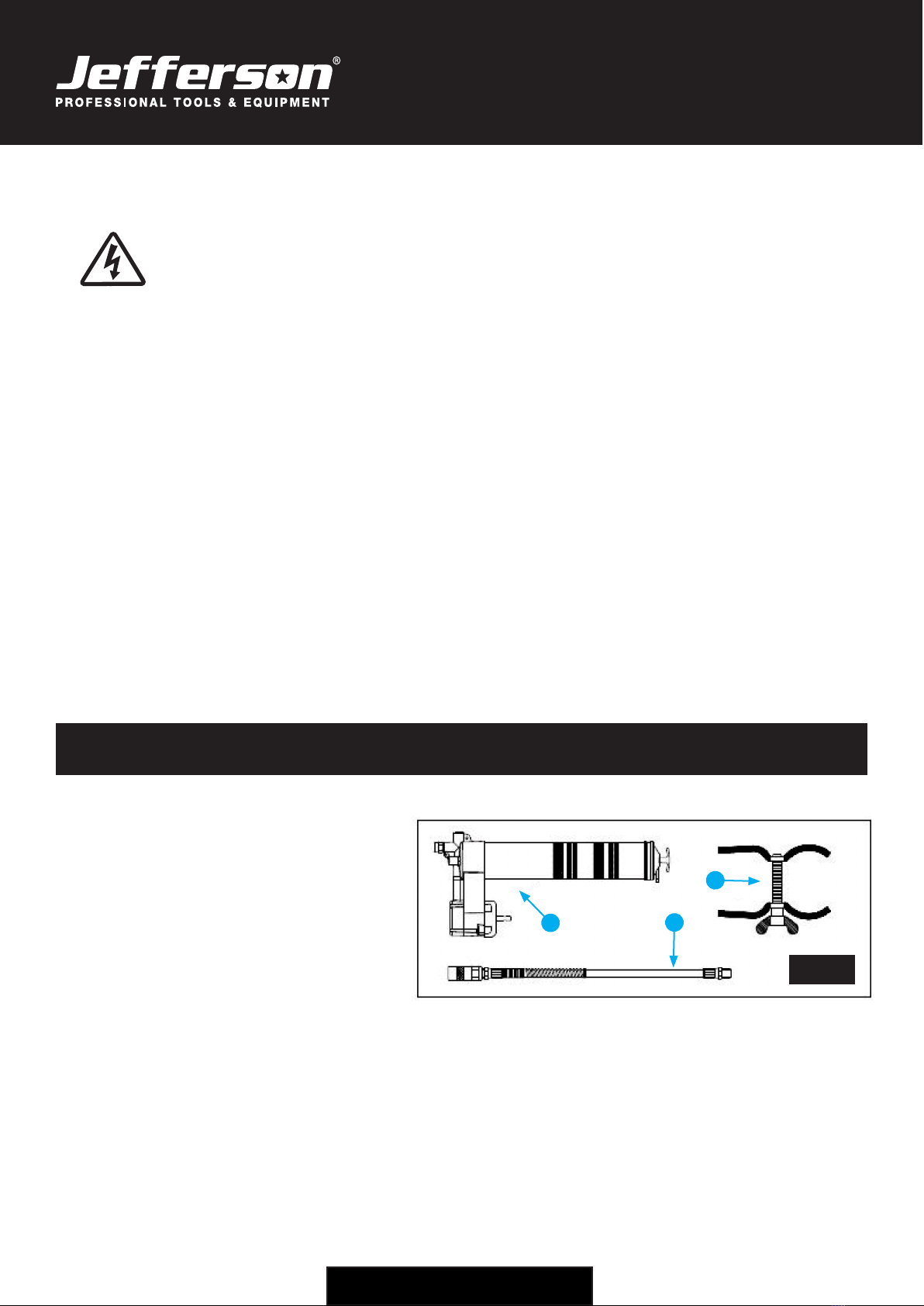
BOX CONTENTS
Check boxed equipment has not been
damaged in transit (see Fig.2) :
1. Grease Gun
2. 18" Nylon Hose
3. Holder
Recycle all packaging materials and keep the
user manual with the equipment for future use.
ASSEMBLY
1. Load the grease to the Container Housing (see Fig.1, #5 page 3) before assembling the coupling greaser. Put the
greaser on a bench or solid surface and connect the power tool to the adaptor (remove any drill bits or adaptors
loaded in the chuck). Further instructions for loading the grease gun are shown on page 7.
2. Loosen the chuck and couple the power tool with the connector on the greaser (see Fig.1, #12 page 3). Tighten
the chuck securely and remove before operation.
3. Unscrew the Buttery Locking Screw (see Fig.1, #10 page 3) on the Holder to allow sufcient room to place one
end over the container tube on the greaser and the other end on the power tool (capacity 1.5" - 3"). Once in position
tighten the buttery until both ends are secure.
4. Connect the 18" High Pressure Nylon Hose to the Grease Gun Outlet (see Fig.1, #2 page 3).
1 2
3
Fig.2
7
USER MANUAL v1.1
JEFUNIPCPGR
UNIVERSAL POWER COUPLING GREASE GUN
www.jeffersontools.com
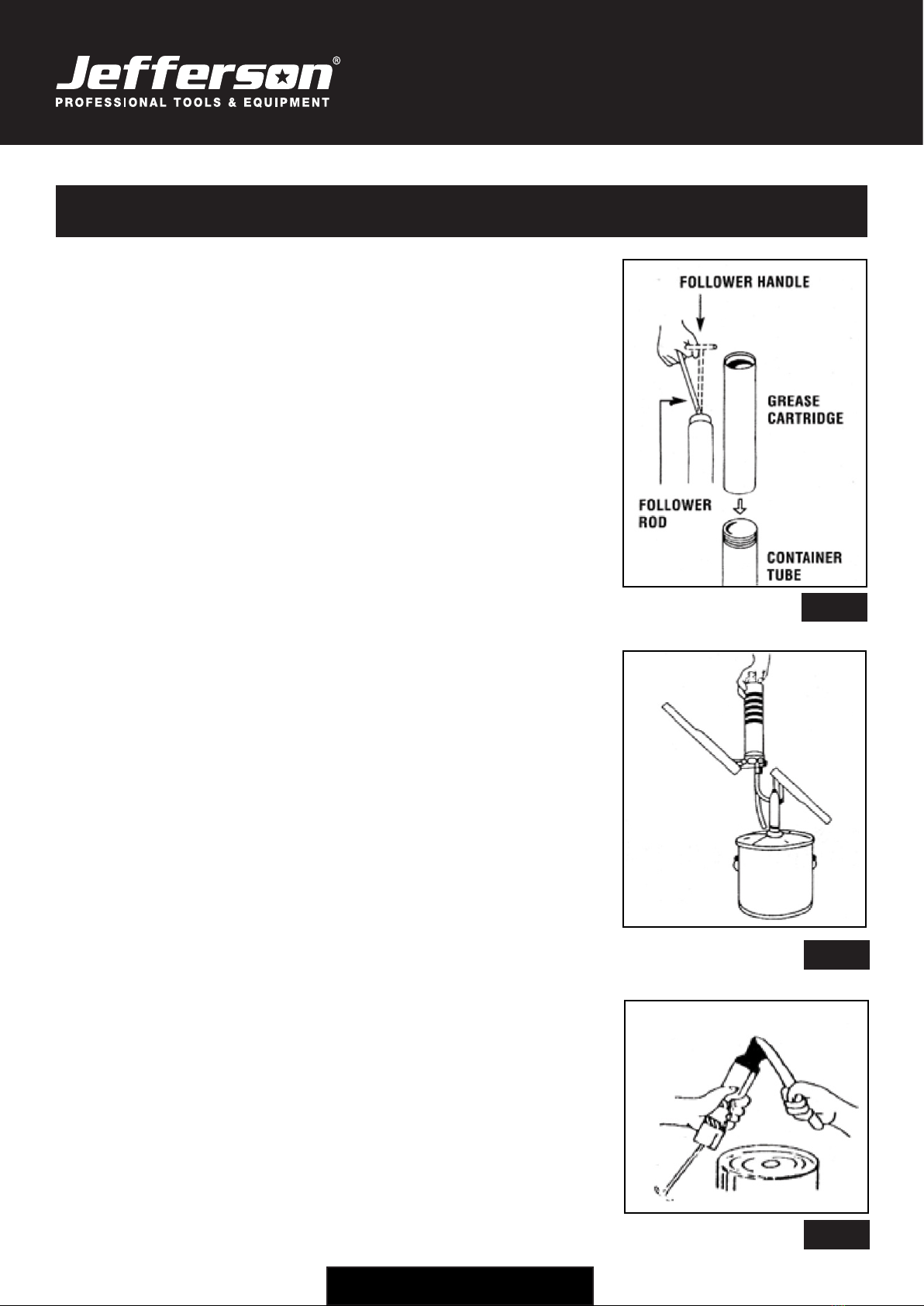
GREASE LOADING
This equipment is compatible with 3 methods of grease loading:
CARTRIDGE LOADING
1. Remove the two ends of the Container Housing (Gun Head and
Plunger Assembly).
2. Pull the Follower Handle back until the Rod is fully extended (carefully
release the follower handle to eject / remove used cartridge, if present).
Pull back the Follower Handle until fully extended then pull it sideways
to latch the Rod groove into the keyhole slot in the container cap (Fig.3)
3. Remove the caps from both ends of the Container Housing and insert
the open end of the cartridge with the metal rimmed end toward the
bottom cap / plunger end.
4. Loosely assemble the head and the Container Housing and disengage
the follower rod from the Container Cap. Engage the Follower Rod with
the Follower by rotating the Follower Handle.
5. Unscrew the Container Housing 1-2 turns from the Gun Head
and Plunger Assembly and exert force on the follower handle until a
little grease is released from the outlet at the Gun Head. Tighten the
Container Housing back into the Gun Head and Plunger Assembly.
6. Disengage the Follower Rod from the Follower by rotating the
Follower Handle. Push the Follower Rod into the container. Then
assemble the Nylon Hose and screw it into the outlet at the Gun Head.
Please Note: Ensure that the grease cartridge is not damaged in
anyway before inserting into the Container Housing. The cartridge
should fit smoothly and require little force to insert. Do not insert the
grease cartridge if it is damaged or warped from its cylindrical shape. If
the cartridge is damaged or warped in anyway the equipment will not
function correctly and the cartridge could become lodged in the housing.
Do not try to re-use empty grease cartridges.
DISPENSER LOADING
1. Remove any used greased cartridges from the Container Housing.
2. Remove the slotted plug from the Gun Head assembly and insert the
required loader tting that is compatible with the pump being used.
3. Extend the level out on the grease gun and insert the loader tting into
the pump adapter and ll as required (Fig.4). Reassemble the housing.
BULK LOADING
1. Remove the gun head from the Container Housing
2. Draw back the Plunger Handle fully.
3. Use a scoop or utensil to add the required amount of grease to the
Container Housing.
4. Reassemble the housing.
Fig.3
Fig.4
Cartridge Loading
Dispenser Loading
Fig.5
Bulk Loading

8
USER MANUAL v1.1
JEFUNIPCPGR
UNIVERSAL POWER COUPLING GREASE GUN
www.jeffersontools.com
OPERATION
Ensure that you have read and fully understand all of the safety requirements for the grease gun and the power tool
you are using.
1. Set the Power Tool to forward drive
2. Push any trapped air iby gently pushing the Plunger into the Container Housing
3. Secure the Nylon Hose Output to the tting which requires the lubrication
4. Press the trigger on the power tool to activate, the grease will begin to lubricate from the hose output
5. To stop, turn off the power tool and disassemble
Warning: Keep hands away from moving parts and grease outlet during operation. Ensure that any electrical power
tools are used within the motor capacity, do not allow motor to overheat. For air powered tools do not exceed the
rated working pressure.
MAINTENANCE
Warning: Risk of electric shock. Always disconnect any equipment from the mains supply before carrying out any
cleaning or maintenance.
• Maintenance and repair must be performed by a qualied person. Do not carry out any maintenance work before
carefully reading the following instructions. Faulty parts should be replaced only with approved components
having the same specications as the original ones.
• Ensure the hose, connections and container housing are kept clean and free from debris before use.
• Oil any moving parts as required.
TROUBLESHOOTING
Symptom Possible Causes Solution
Power tool running but no
lubrication from the grease gun.
1. Possible air lock.
1. Disconnect the power tool and disassemble the container
housing . Remove the plunger rod fully and then push it rmly
back into the container to release the trapped air. Repeat if
necessary until the grease begins to ow. Reassemble.
Plunger will not enter the grease
cartridge.
1. The cartridge is not compatible.
2. The cartridge may be warped or
damaged at the rim.
1. Fit a compatible cartridge.
2. Fit a cartridge that is not damaged.
Leakage from the gun head. 1.The nylon hose is not tightened securely
at the gun outlet.
1. Screw / tighten the hose and ensure that it is secure.
9
USER MANUAL v1.1
JEFUNIPCPGR
UNIVERSAL POWER COUPLING GREASE GUN
www.jeffersontools.com
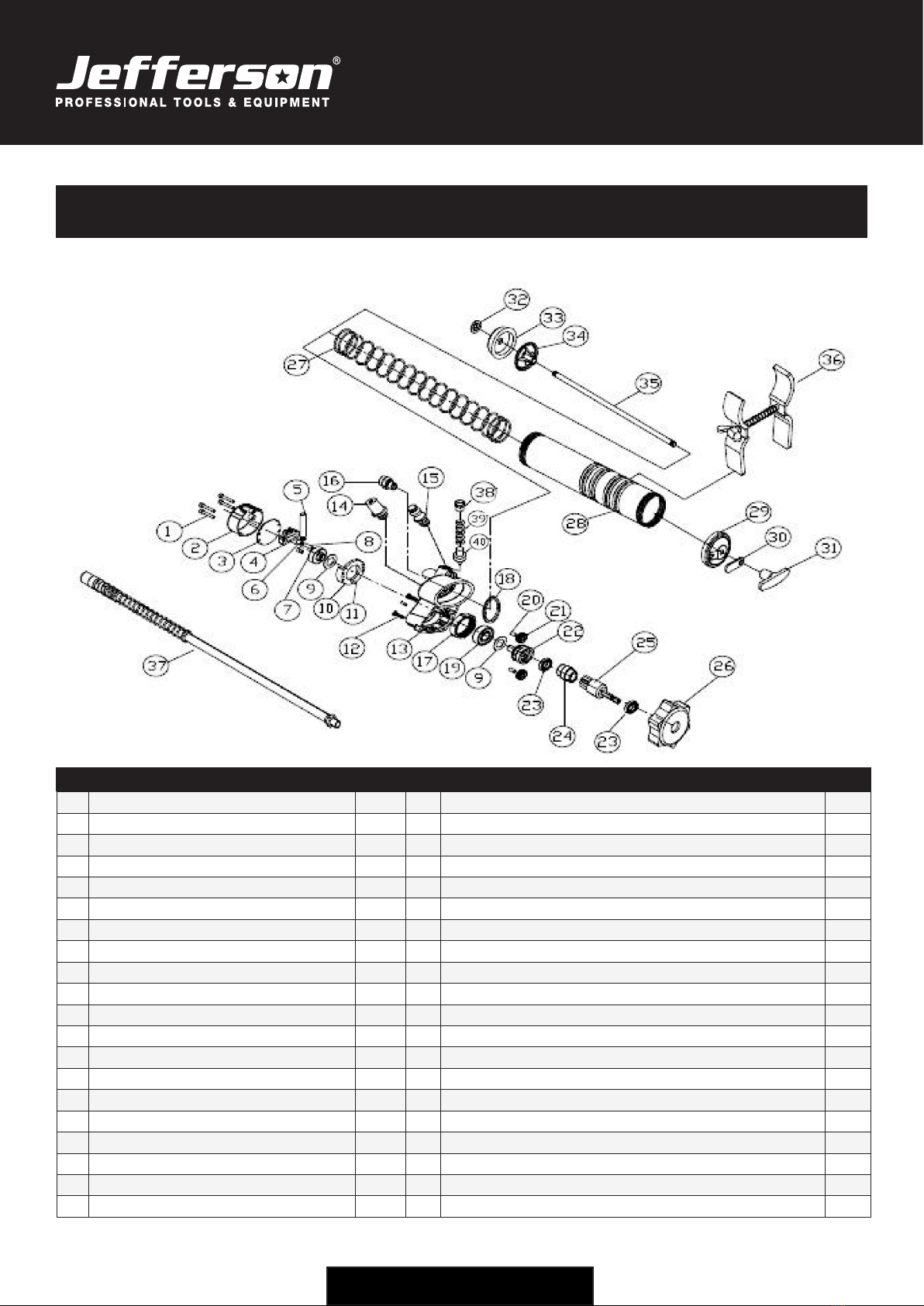
PARTS LIST & DIAGRAM
# Description Qty # Description Qty
1Screw 4 21 Small Gear 2
2Gear Cap 1 22 Control Axle 1
3Cap Plate 1 23 Axle Bearing 2
4Piston Controller 1 24 Bearing Divider 1
5PIston 1 25 Jointer 1
6Axle Guide 1 26 Protective Cover 1
7Roller 1 27 Long Spring Kit 1
8Roller Pin 1 28 Container Tube 1
9Washer 2 29 Bottom Plate 1
10 Controller Body 1 30 Catch Plate 1
11 Body Pin 2 31 Plunger Handle 1
12 Screw 4 32 Plunger Washer 1
13 Gun Holder 1 33 Plunger 1
14 Filler Plug 1 34 Backlash Gasket 1
15 Air Vent Valve 1 35 Plunger Rod 1
16 Adapter 1 36 Holder 1
17 Gear Holder 1 37 18" High Pressure Nylon Hose 1
18 Gasket 1 38 Round Plug 1
19 Roller Bearing 1 39 Pressure Vent 1
20 Gear Pin 2 40 Vent Spring 1

10
USER MANUAL v1.1
JEFUNIPCPGR
UNIVERSAL POWER COUPLING GREASE GUN
www.jeffersontools.com
LIMITED WARRANTY STATEMENT
Jefferson Professional Tools & Equipment, or hereafter "Jefferson" warrants its customers that its products will be free of defects in workmanship
or material. Jefferson shall, upon suitable notication, correct any defects, by repair or replacement, of any parts or components of this product
that are determined by Jefferson to be faulty or defective.
This warranty is void if the equipment has been subjected to improper installation, storage, alteration, abnormal operations, improper care, service
or repair.
Warranty Period
Jefferson will assume both the parts and labour expense of correcting defects during the stated warranty periods below.
All warranty periods start from the date of purchase from an authorised Jefferson dealer. If proof of purchase is unavailable from the end user, then
the date of purchase will be deemed to be 3 months after the initial sale to the distributor.
1 Year
JEFUNIPCPGR - UNIVERSAL POWER COUPLING GREASE GUN
90 Days
• All replacement parts purchased outside of the warranty period
Important: All parts used in the repair or replacement of warranty covered equipment will be subject to a minimum of 90 days cover or the
remaining duration of the warranty period from the original date of purchase.
Warranty Registration / Activation
You can register and activate your warranty by visiting the Jefferson Tools website using the following address:
www.jeffersontools.com/warranty and completing the online form. Online warranty registration is recommended as it eliminates the need to
provide proof of purchase should a warranty claim be necessary.
Warranty Repair
Should Jefferson confirm the existence of any defect covered by this warranty the defect will be corrected by repair or replacement at an
authorized Jefferson dealer or repair centre.
Packaging & Freight Costs
The customer is responsible for the packaging of the equipment and making it ready for collection. Jefferson will arrange collection and
transportation of any equipment returned under warranty. Upon inspection of the equipment, if no defect can be found or the equipment is not
covered under the terms of the Jefferson warranty, the customer will be liable for any labour and return transportation costs incurred. These costs
will be agreed with the customer before the machine is returned.
*Jefferson reserve the right to void any warranty for damages identified as being caused through misuse
Warranty Limitations
Jefferson will not accept responsibility or liability for repairs made by unauthorised technicians or engineers. Jefferson's liability under this
warranty will not exceed the cost of correcting the defect of the Jefferson products.
Jefferson will not be liable for incidental or consequential damages (such as loss of business or hire of substitute equipment etc.) caused by
the defect or the time involved to correct the defect. This written warranty is the only express warranty provided by Jefferson with respect to its
products.
Any warranties of merchantability are limited to the duration of this limited warranty for the equipment involved.
Jefferson is not responsible for cable wear due to flexing and abrasion. The end user is responsible for routine inspection of cables for possible
wear and to correct any issues prior to cable failure.

11
USER MANUAL v1.1
JEFUNIPCPGR
UNIVERSAL POWER COUPLING GREASE GUN
www.jeffersontools.com
Claiming Warranty Coverage
The end user must contact Jefferson Professional Tools & Equipment (Tel: +44 (0) 1244 646 048) or their nearest authorised Jefferson dealer where
final determination of the warranty coverage can be ascertained.
Step 1 - Reporting the Defect
Online Method:
• Visit our website www.jeffersontools.com/warranty and complete the Warranty Returns form. You can complete the form online and submit it
to us directly or download the form to print out and return by post.
Telephone Method:
Contact your Jefferson dealer or sales representative with the following information:
• Model number
• Serial number (usually located on the specification plate)
• Date of purchase
A Warranty Returns form will be sent to you for completion and return by post or fax, together with details of your nearest authorised Jefferson
repair centre. On receipt of this form Jefferson will arrange to collect the equipment from you at the earliest convenience.
Step 2 - Returning the Equipment
It is the customer's responsibility to ensure that the equipment is appropriately and securely packaged for collection, together with a copy of
the original proof of purchase. Please note that Jefferson cannot assume any responsibility for any damage incurred to equipment during
transit. Any claims against a third party courier will be dealt with under the terms & conditions of their road haulage association directives.
NOTE: Jefferson will be unable to collect or process any warranty requests without a copy of the original proof of purchase.
Step 3 - Assessment and Repair
On receipt, the equipment will be assessed by an authorised Jefferson engineer and it will be determined if the equipment is defective and in need
of repair and any repairs needed are covered by the warranty policy. In order to qualify for warranty cover all equipment presented must have been
used, serviced and maintained as instructed in the user manual.
Where repair is not covered by the warranty a quotation for repair, labour costs and return delivery will be sent to the customer (normally within 7
working days).
NOTE: If the repair quotation is not accepted Jefferson Professional Tools & Equipment will invoice 1 hour labour time at £30 per hour plus
return carriage costs (plus VAT).
In cases where no fault can be found with the equipment, or, if incorrect operation of the equipment is identified as the cause of the problem, a
minimum of 1 hour labour at £30 per hour plus carriage costs will be required before the equipment will be despatched back to the customer.
Any equipment repaired or replaced under warranty will normally be ready for shipment back to the customer within 7 working days upon receipt
of the equipment at an authorised Jefferson Repair centre (subject to part availability). Where parts are not immediately available Jefferson will
contact you with a revised date for completion of the repair.
General Warranty Enquiries
For any further information relating to Jefferson warranty cover please call +44 (0) 1244 646 048 or send your enquiry
Disclaimer:
The information in this document is to the best of our knowledge true and accurate, but all recommendations or suggestions are made without
guarantee. Since the conditions of use are beyond their control, Jefferson Tools® disclaim any liability for loss or damage suffered from the use of
this data or suggestions. Furthermore, no liability is accepted if use of any product in accordance with this data or suggestions infringes any patent.
Jefferson Tools® reserve the right to change product specifications and warranty statements without further notification. All images are for
illustration purposes only.

Jefferson Tools,
Herons Way,
Chester Business Park,
Chester,
United Kingdom,
CH4 9QR
Tel. +44 (0)1244 646 048
Email: [email protected]
IMPORTANT! SAFETY FIRST!
Before attempting to use this product please read
all the safety precautions and operating instructions
outlined in this manual to reduce the risk of fire,
electric shock or personal injury.
www.jeffersontools.com
Table of contents
Other Jefferson Tools manuals

Jefferson
Jefferson JEFBGSSTDADJ User manual

Jefferson
Jefferson JEFARIVT02H User manual

Jefferson
Jefferson JEFHOSRL15-3/8HVP User manual

Jefferson
Jefferson JEFHOSRLH15-1/2 User manual

Jefferson
Jefferson JEFLUGGUN03 User manual

Jefferson
Jefferson JEFTRCH09ILSG User manual

Jefferson
Jefferson JEFHTG2S-230 User manual
Popular Tools manuals by other brands


ReelCraft
ReelCraft 82000 OLP Operating instructions and parts list

VONROC
VONROC GC501XX Original instructions

REED
REED True Peel operating instructions

Dynabrade
Dynabrade 53472 Disassembly & Assembly Instructions

Amkus
Amkus C700 INSTRUCTIONS FOR SAFE OPERATION AND MAINTENANCE

LAJAC
LAJAC HOSR quick start guide


