ETG LTM-1000 User manual
ETG – In-Pavement Loop Tester
Model Number:
Original Revision 1.0 March 2007 man__a.doc
This revision 27-07-2012 Rev F

2
Contents
1Equipment description
2Loop Detector functional specification
3Equipment electrical and Physical specification
Legislative and Regulatory Compliance
RoHS - EU Directive 2002/95/EC per Category 9 / Annex IA – Exempt until 2010
Electrical Power surge 1kV - rise time 1.2sec/hold 50 secs
CE / Ctick compliant IEC1000-4-5/ EN61000-4-5
Note: This is not a laboratory test instrument. This is a purpose designed field test instrument that
facilitates evaluation of in-pavement loop characteristics including; inductance, DC Resistance, tuned
frequency, ‘Q’ and insulation integrity.
! ! ! ! ! W A R N I N G ***** C A U T I O N ! ! ! !
EXTREME CARE REQUIRED WHEN using the insulation breakdown test function. This is a
controlled voltage ‘Megger’ test where typically 500V is applied to the output pins for a preset period
(100milliseconds) while the microcomputer monitors the resistance to earth.
DISCLAIMER
Excel Technology Group Pty Ltd reserves the right to make changes to the technology described in this document without notice
and advises its clients to obtain the latest version of the relevant information prior to placing an order. Excel Technology Group
Pty Ltd warrants its products to the specification detailed herein in accordance with standard conditions of sale, client
specification, and conditions imposed through government legislation.
Testing and product control techniques are utilised to the extent that Excel Technology Group Pty Ltd deems necessary to
support the relevant specification and warranty. Excel Technology Group Pty Ltd acknowledges the proprietary information
provided by Third Party component suppliers however, Excel Technology Group Pty Ltd assumes No Responsibility for the use
of any other circuit or device other than the circuitry embodied on Excel Technology Group Pty Ltd numbered engineering
drawings and on Excel Technology Group Pty Ltd circuit cards as identified according to the requirements of the Circuit Layouts
Act 1989 (Australia). Excel Technology Group Pty Ltd is not liable for any damage consequential or otherwise related to the use
of this equipment.
Excel Technology Group Pty Ltd grants the user/client rights to reproduce any of the documents contained herein but not subject
to conditions of ‘Non-Disclosure’, providing such reproduction is conducted with no alteration to any material written, drawn or
otherwise reproduced and/or contained in this document.

3
The LT-1000M in-pavement loop tester
Enhanced features from the LTM100
•Loop Location – moving vehicle, audible ‘ping’ when loop detected
•Loop ‘winding’ location – hand held operation walking on road surface
•Loop wire Insulation Integrity
This is a field service device suitable for in-pavement loop analysis. The device has an LCD display
which displays all relevant in-pavement loop parameters including; DC Resistance, Inductance, Loop
‘Q’, Loop tuned frequency, insulation integrity and Loop location. Additionally an analogue bargraph
display indicates a vehicle actuation and relevant energy change associated with the actual vehicle
detection.
This purpose designed, rugged, portable hand held device connects to loop feeder cables via flexible
leads with ‘alligator’ style clips. The loop location function requires an external ‘ tuned’ probe. The
device has an LCD panel for displaying relevant loop parameters. The device has a single power-ON /
OFF momentary switch and for night-time use the touch sensitive keypad for backlight operation will
activate the back light when selected to save energy. The analyser is powered by a single 9V D cell.
The device will automatically switch OFF after a preset period to enable longer battery life – WHEN
disconnected from a loop. Activating the ON button ‘wakes up’ the internal microprocessor which
then controls battery power for a preset period. Inactivity will cause the microprocessor to return to
‘sleep’ mode. The OFF function is selected via the ON /OFF switch which is a momentary operation
in both directions
There are no external adjustments. The device will automatically detect the loop parameters and report
the parameters on the LCD screen. The device indicates battery voltage and when the battery becomes
low should be replaced in order for the internal measurement circuit to produce an error free analysis of
the loop parameters.
The field technician can identify the following in-pavement loop verification
•The DC Resistance of the loop and feeder
•The Inductance of the combined loop and feeder
•The Tuned frequency of the loop and feeder
•The ‘Q’ of the combined loop and feeder
•Quickly identify ‘short-circuits’
•Quickly identify ‘open-circuits’
•Loop position within the pavement identified from a moving vehicle (max speed 110khr)
•Loop wire (winding) location +\- 1 cm (hand-held operation)
•Loop wire insulation integrity >100Megohms
•Loop operation incorporating an analogue bargraph display of the actuation
4
Instructions for Measuring Loop Characteristics
Step 1
Connect the two loop feeder leads using the alligator clips. There is no polarity however the clips
should be attached in a manner which does not short circuit the connectors that would cause
malfunction and or false readings.
Step 2
Switch on the unit via the ON/OFF switch – the unit will automatically switch off after a preset period
of no activity. The unit will hold on and display data while connected to a loop.
Step 3
If using the LTM 1000 at night press the momentary button to enable the backlight. Excessive use of
the backlight will decrease the battery life.
Step 4
The screen display is self explanatory
Frequency: Is the resonant frequency of the loop (Typically 15-140Khz).
Inductance: Is the inductance value of the loop (Typically 40-700 MicroHenries)
Resistance: Is the DC resistance of the loop (Typically 1-3ohms)
‘Q’: Is the performance value of the loop (Typically >6)*
* For vehicle classification > 12 is appropriate
OPEN CIRCUIT - This message is displayed if the loop is open circuit
SHORT CIRCUIT - This message is displayed if the instrument identifies a short circuit
Loops and loop feeder cables are all part of the in-pavement loop circuit and an extension of the vehicle
detector circuitry. A suggested analysis procedure is to commence at the detector and progress
backwards to the actual in-pavement loop in compartmentalized steps. It is important for the ‘Q’
calculation to evaluate the complete in-pavement circuit including the loop PLUS the feeder cable
(refer to notes herein concerning calculation of ‘Q’).
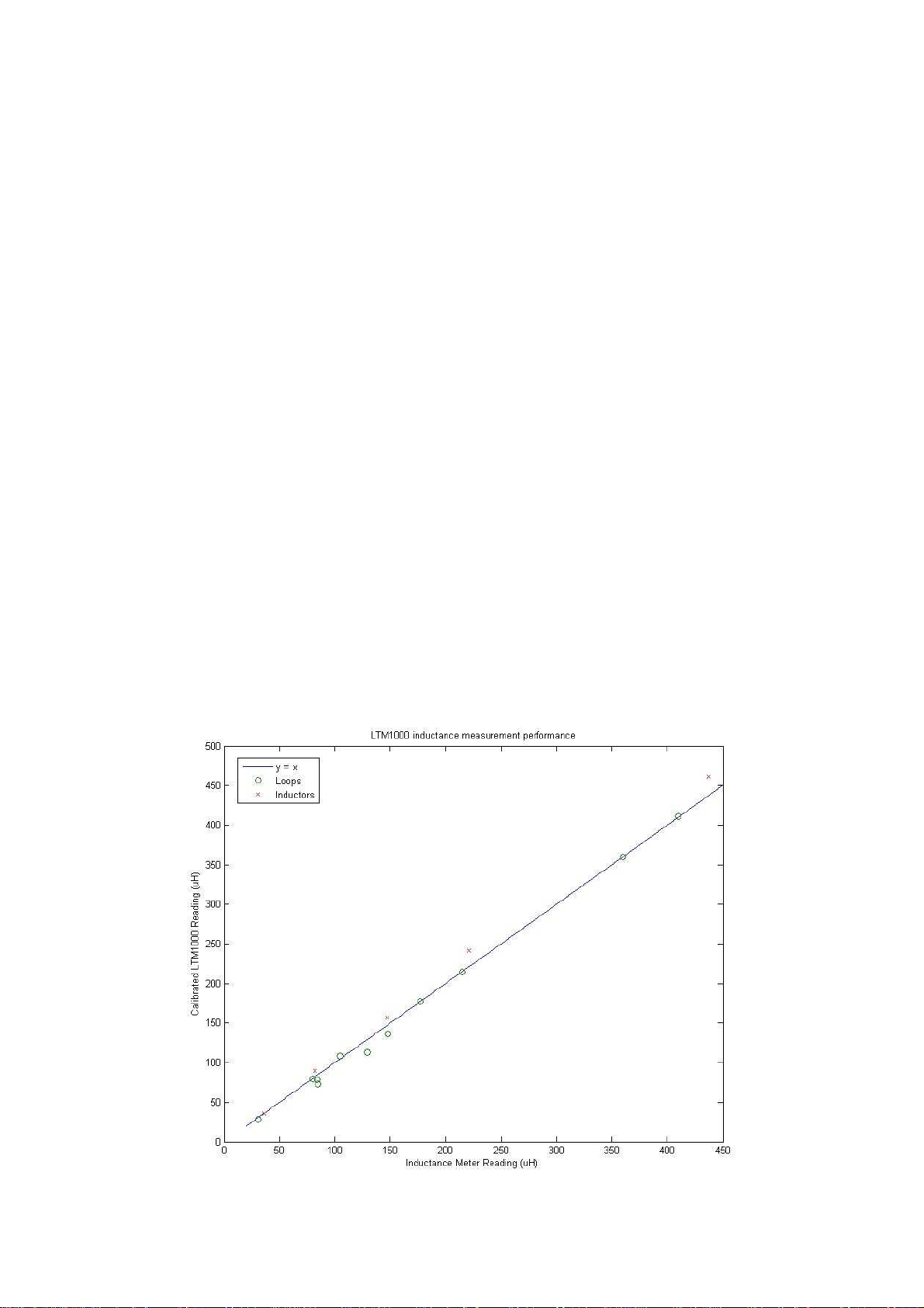
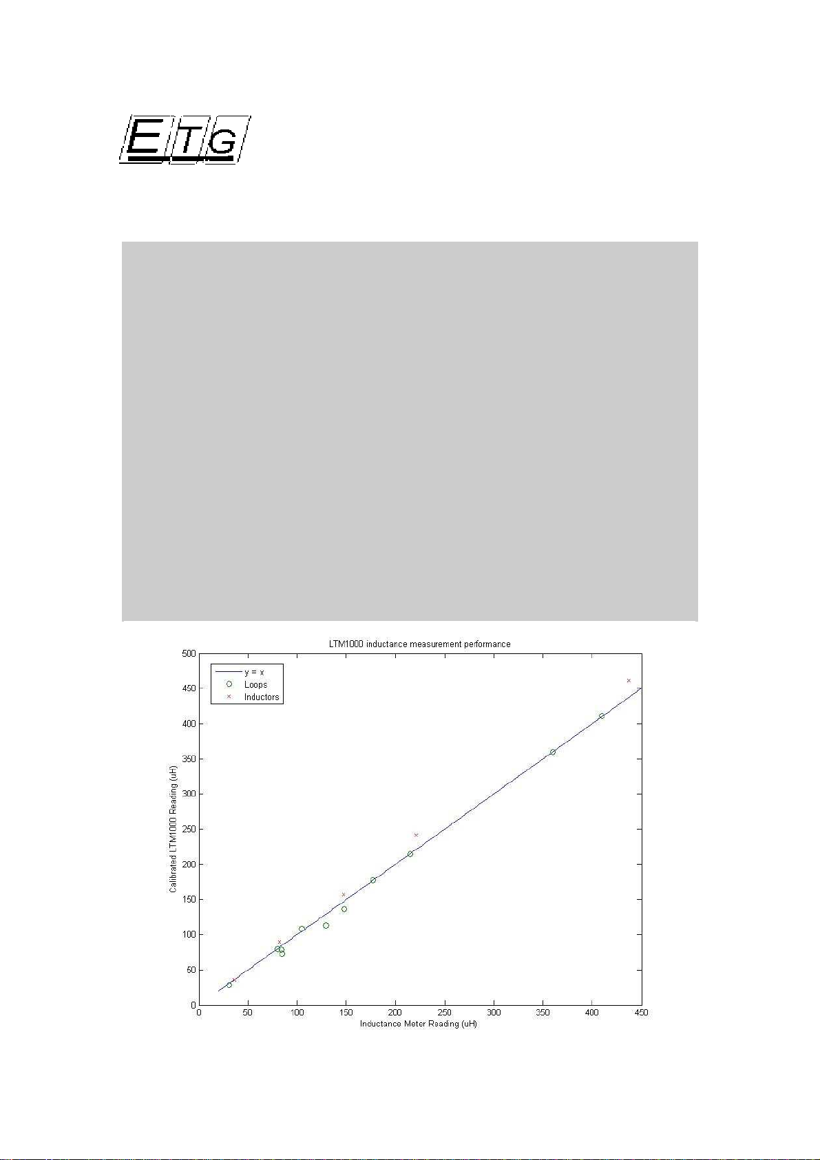
Inductance Schedule – Measurement Tolerance

5
Instructions for Evaluating Insulation Integrity
! ! ! ! ! W A R N I N G !!!!!!! C A U T I O N ! ! ! !
EXTREME CARE REQUIRED WHEN using the insulation breakdown test function. This is a
controlled voltage ‘Megger’ test where typically 500V is applied to the output pins for a preset period
(100milliseconds) while the microcomputer monitors the resistance to earth. The test is an automated
sequence and an indicative measurement is displayed on the LCD.
Step 1:
DISCONNECT THE LOOP AND FEEDER FROM ALL OTHER EQUIPMENT IN THE CABIENT.
THE HIGH VOLTAGE ASSOCIATED WITH THIS TEST WILL DAMAGE THE SENSITIVE
ELECTRONIC CIRCUITRY ASSOCIATED WITH VEHICLE DETECTION.
Step 2:
Make sure the TESTER is switched OFF – verify the LCD display is BLANK
Connect the RED lead to a single loop wire. Connect the Black wire to an appropriate EARTH
connection point.
Step 3:
Switch on the device and select the insulation integrity test. Select the test function again and an
audible ‘click from the relay switching will be displayed.
The device will generate the 500V pulse required by the test for a sustained period to enable a
resistance measurement to be determined. An indicative insulation resistance will be displayed on the
LCD display. The qualification for what is a PASS or FAIL is done by the operator to eliminate test
variables associated with the same loop and battery level. This is not a laboratory instrument and the
measurement is an indicative measurement.
This instrument has been Factory Test Certified at the following levels of resistance;
10MegOhm (±5%), 50MegOhm (±5-10%) and 200MegOhm (±10%). A resistor network composed of
0.5watt 10MegOhm resistors is used for this test. It is acknowledged that the environment is
reasonably stable and percentage tolerance in resistor values may impact on this test.
Insulation Integrity Test Range
Resistance =< 10Megohm
Indicates a resistance less than 10MegOhm
Resistance > 10MegOhms
Indicates a resistance greater than 10 MegOhm but less than 200MegOhms
Resistance > 200MegOhms
Indicates a resistance greater than 200MegOhms
The measurement range displayed by the instrument allows the operator to make an informed decision
about the loops insulation integrity as different road authorities have stated variations in accepted
winding to earth insulation resistance thresholds.
Note on Insulation Resistance Measurement
The calibration of the instrument provides for a higher tolerance in the resistance range of 5 to 15
MegOhms. The instrument performance significantly decreases in the range less than 5MegOhms.
The Insulation Resistance measurement is an indicative measurement of the nominal state of the loop.
The objective of this test function is to provide an objective TEST OK or FAIL status for the loop and
feeder cable. Variations in battery level capacity and rapid repetitive testing producing accumulated
mutual capacitance resulting from moisture ingress in the cable and field joints will effect readings.
Laboratory testing indicated that the same loop measured after a days rain, 4 hours since the last rain
fell and on a dry day will indicate three different resistance readings.

6
Instructions for Locating ‘active’ Loops - from a Moving Vehicle
An audible ‘PING’ sound is emitted when an active in-pavement loop electromagnetic field is detected.
The external probe must be located and secured approximately 50cms from the road surface in a
manner such that there is direct line of sight between the probe and the road surface. A location with
no metal between the vehicle and the road surface will provide the best results. The probe may be hung
from the door and the door closed carefully onto the cable to avoid damage to the cable. The vehicle
must be driven in a manner that enables the probe to pass within the boundary of the in-pavement loop
to provide the best results.
The vehicle should be driven in a safe manner with the drivers attention to the driving function being of
primary importance and therefore it is recommended that the task requires a driver and an ‘observer’.
The vehicle may be driven at speeds between 20kmhr and 100kmhr in accordance with the speed limits
and nominal speed of surrounding vehicles.
** THERE IS NO VISUAL DISPLAY TO DISTRACT THE DRIVER ***
The location where the audible ping is emitted should be noted by the observer.
Instructions for Locating a Loop Winding – Walking on the road surface
! ! ! ! ! W A R N I N G !!!!!!! C A U T I O N ! ! ! !
This function requires the operator to walk on the road where the in-pavement loop is
located. This function requires the operator to view the display in order to find the
position of the loop wire within 2 cms positional accuracy. Therefore the operator
must have taken appropriate steps to make the section of road safe where the test is
being performed as it is not possible to observe the instrument AND observe
approaching vehicles simultaneously. This specific nature of this requirement may
vary according to different jurisdictions and local OH&S legislation. The loop location
test should only be undertaken when the operator is in no danger from moving
vehicles on the road surface.
The external probe should be swept over the area where the loop is located. The probe is located
approximately 5-10cms above the road surface. An audible ‘ping’ will indicate that the probe is
within a loop field and the display will rise as in (a) below and the boxes located at the bottom of the
LCD display will darken / filling in black (c ).
The probe is moved back and forth to confirm the presence of an electromagnetic field. When
attempting to locate a loop winding wire best results are achieved when the probe is drawn from within
the in-pavement loop to outside of the in-pavement loop. The display indicates a HIGH level when a
field is detected. The field is present inside the loop and for a short distance outside the loop. When
the probe is directly on top of the loop winding wire the field is ZERO – this is the position of the
loop winding. This is indicated by the dip (or sustained dip if held in the same position) in (b) below
and the box display (c ) progresses quickly from darken boxes to empty boxes and naturally back to
darken when the probe is moved off the position directly above the loop wire winding.
________
(a) ____| Signal goes high when a field is detected
________________ _____________
(b) ____| |_| The signal dips when the probe is directly over the
wire winding
(c ) ▒▒▒▒▒▒- Empty rectangular boxes are displayed bottom right of LCD
███When a signal level is detected these boxes will darken

7
Addendum
Note on Insulation Resistance measurement
The Insulation Resistance measurement is an indicative measurement of the nominal state of the loop.
The objective of this test function is to provide an objective TEST OK or FAIL status for the loop and
feeder cable. Variations in battery level capacity and rapid repetitive testing producing accumulated
mutual capacitance resulting from moisture ingress in the cable and field joints will effect readings.
Note on the nature of detecting the position of a loop winding
The most sensitive area of a loop is above the loop wire itself as the lines of force are at RIGHT
ANGLES to the eddy current circuit producing the largest opposing force. The ‘right angle’ force
however when measured with the probe field at right angles produces a NULL field. The NULL field
is detected by the circuitry and thus the position of the wire is determined. Trawling the probe over
the loop other than in a completely horizontal orientation may induce erroneous results as the angle of
incidence between the loop field and the device probe field will induce a reading.
Note on the validity of cross-talk compensation by simple adjustment of capacitance
Resonant frequency change is the basis of inductive vehicle detection
ωis the frequency in radians/sec
For a resonant circuit:
ω= 1 / SQRT(LC)
therefore ωis proportional to 1/SQRT(L) or L^-0.5
Therefore any variation in L of X% translates to a much smaller variation of ω. However, this
variation is not affected by C. C only affects the absolute value of ω.
What does all this mean? Changing the resonant frequency point for a fixed inductor (a loop)
requires changing the capacitance C. However . . .
Since C is not related to the change in
ω
when L changes - it can be stated that doing so is a pointless
exercise unless the frequency is be shifted by at least 5Khz and the device must easily accommodate
site variations while incurring preset incremental capacitance steps.
Note on ‘Q’ calculation (effective performance of the loop)
*’Q’ for normal vehicle detection may be as low as 6 however for vehicle classification applications
and accurate speed detection ‘Q’ should be greater than 15.
Q or the performance of the loop is effectively the relationship between inductance of the loop
and resistance / impedance in the feeder cable hence longer feeders (higher
impedance/resistance) need more inductance in the loop for compensation.
The following formula and reference gives it a scientific presence:
Q (at resonance) = Frequency (radians) X[Multiplied by ] inductance (henries)
__________________________________________ [divided]
DC Resistance (ohms)
** Where Radians = 2 (multiplied) pi (multiplied) hz
Reference: Electronics A Top-down approach to computer-aided circuit design by Hamley 1994
P904-908
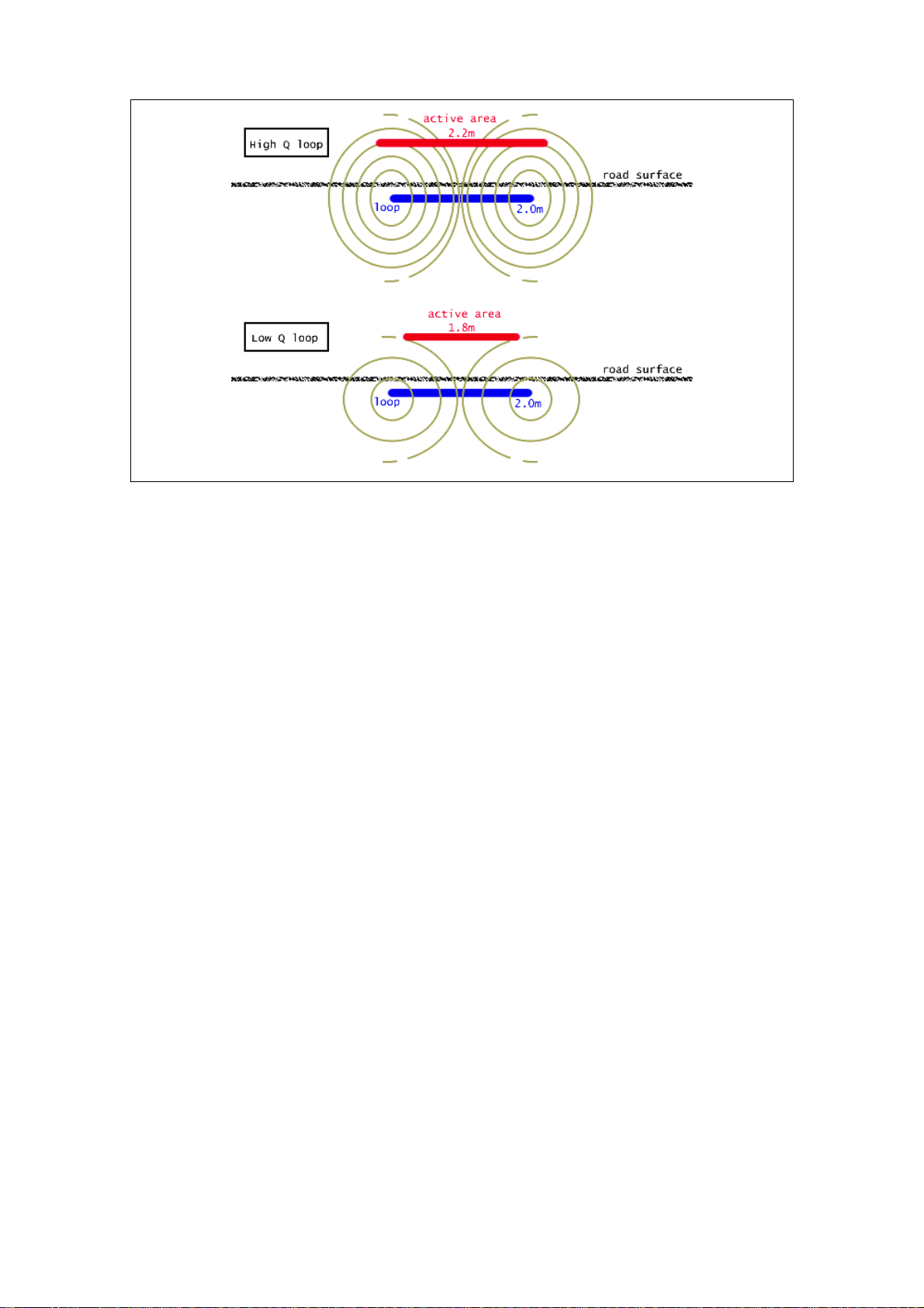
Loop length is the length of the active area of the loop in the direction of travel. The active area is size
of the loop electromagnetic field in which a vehicle will change the inductance of the loop above the
detection threshold. The size of the active area is determined by, the sensitivity of the loop (Q), the
depth of the loop, and the sensitivity of the detector.
8
Loop Length and Sensitivity
Loop length and sensitivity is associated with the length of the active area of the loop in the direction of
travel and the strength of the electromagnetic field and its inherent interaction with the electromagnetic
of iron. . The active area is size of the loop electromagnetic field in which a vehicle will change the
inductance of the loop above the detection threshold. The size of the active area is determined by the
sensitivity of the loop (Q), the depth of the loop, and the sensitivity of the detector.
For loops installed according to the specifications given in XL Series loop detector manual ,
the active area of the loop should be close to the physical loop size. For existing loops with
low Q the active area may be diminished.
A low loop ‘Q’ will effect the performance of the detector both in respect to detecting smaller
vehicle and the accuracy achievable by the vehicle detector in measuring the vehicle length.
The following example indicates how low ‘Q’ effects vehicle length measurement and how
adjustments in the detctor may overcome the measurement error.
The error in the loop length directly affects the error in the vehicle length. For example if there
is an error in the loop length of -0.4m then vehicles will be reported as being 0.4m shorter
than they actually are. This error can be minimised by following these steps:
1. Set the detectors to the most sensitive setting possible without crosstalk (crosstalk
can only occur between cards)
2. Using the debug mode in the console, observe the lengths of 5 or more Holden or
Ford sedans. These cars have a typical length of 4.9m
3. Average the results and subtract 4.9m.
4. The result is the amount by which the loop length value should be modified.
5. For example: 5 vehicles are measured at 4.1m, 4.3m, 4.0m, 4.0m 4.1m. The average
is 4.1m. Subtracting 4.9 gives – 0.8m. Therefore the loop length should be decreased
by 0.8m.
9
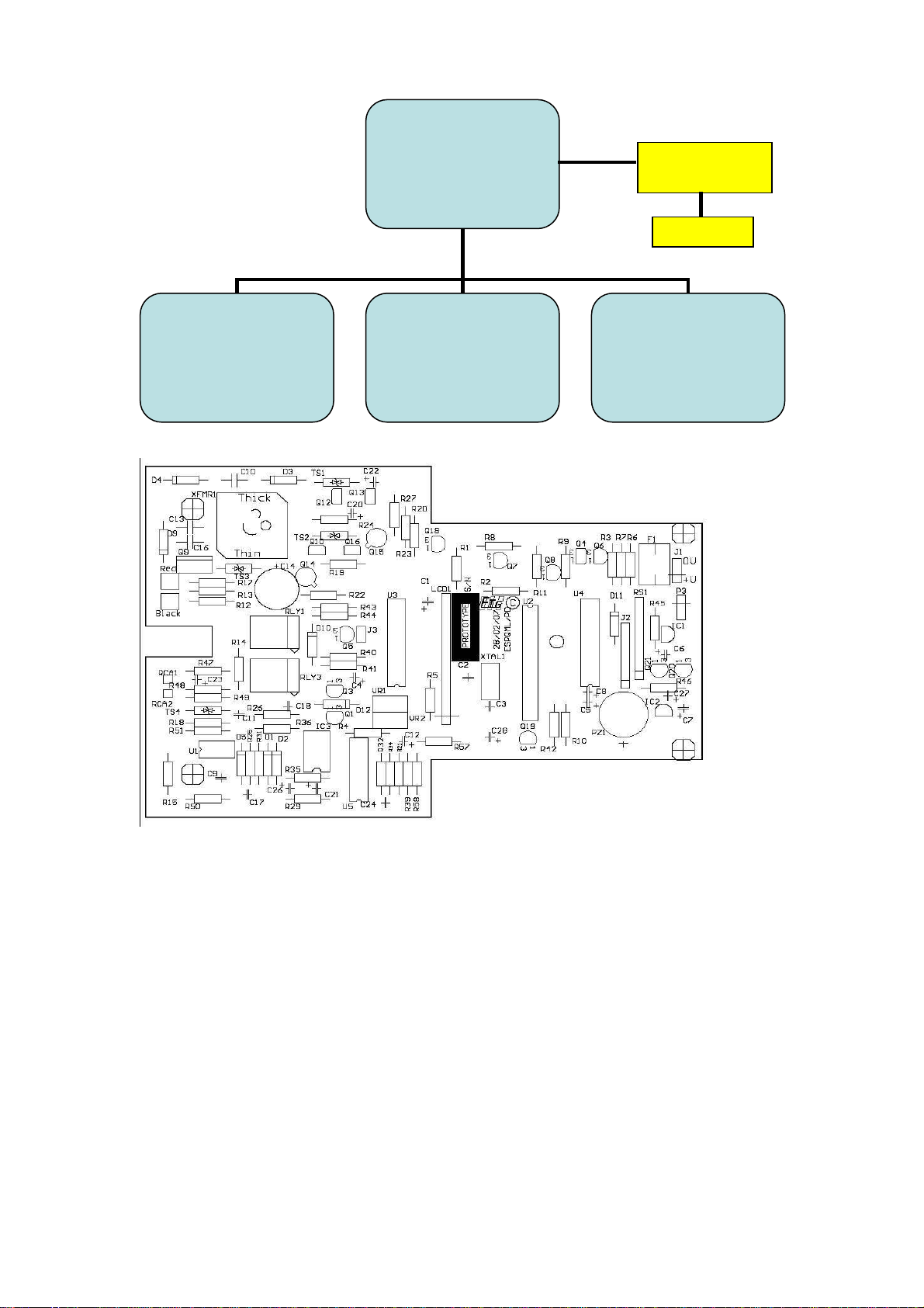
LTM-1000 Main Circuit Board Layout
These drawings provide a functional block representation of the in-pavement loop tester. The device
has a single 9 Volt battery source. The power management circuitry converts the 9volts to 12volts and
5 volts. The 5VDC source is utilized by the microcontroller and logic circuitry. The 12VDC source is
utilized by the loop drive and sense circuitry. An LCD display provides status and measurement data
to the user and functions are selected via touch pad circuitry mounted on the front of the device.
This circuitry, which is driven by the microcontroller excites the in-pavement loop to operate at its
‘tuned’ or resonant frequency. This excitation is a function of the loops resistance, inductance,
capacitance, susceptance and other minor electrical characteristics. The microcontroller searches for
resonance and then computes the related values of resistance, inductance and ‘Q’ within the resonance
equation.
The tester has a high voltage generation circuit which produces 500Vs for approximately 1 second in
order to verify that the insulation integrity (resistance) is greater than 100meg ohms to earth.
The tester incorporates a tuned input circuit connected via a coil located within the external probe.
This enables the operator to search for an electromagnetic field with a frequency within a typical loop
frequency range of 40-140Khz.
Microcontroller
|
LCD DISPLAY
MODULE
|
Touch PAD input
Loop Resonator Circuit
This circuit energises the loop
to its resonant frequency –
enabling measurement of
inductance, resistance, tuned
frequency and ‘Q’
Loop Locator Circuit
This circuit detects and
responds to electromagnetic
energy frequency in the range
of 40Khz to 140Khz (typical
loop resonant excitation
frequency)
Insulation Integrity
High Voltage Generation
Circuit
500V For approx. 1 second
Resistance > 100Megohm
9VDC Battery
12VDC & 5VDC
‘switch on/off’

10
Detector Test Equipment General Specification
General Performance Specification
•Vehicle detector function self tuning in the range of 50 to 800 microHenries
•Typical Loop frequency range between 40kHz and 150kHz.
•Typical Loop inductance range 40 to 800 Microhenries
•Optimised measurement accuracy ‘mid inductance range’ between 100 and 400 microhenries
•Measurement accuracy typically 3% >120microhenries
General Operational Specification
Manual ON - momentary switch actuation ON (Circuit operation sustained by internal microcontroller)
Manual OFF – momentary switch actuation OFF.
Shutdown timer approximately 15 seconds – after removal from loop connection
Loop location from moving vehicle ‘sweep’ – maximum speed 110khr
Loop winding location from walking ‘sweep’ +/- 1 CM
Loop insulation integrity >100Megohms
General Electrical Specification
Serial Ports (Where applicable)
Ethernet, RS232C and RS422 IEEE electrical signal level compatible. Configuration port baud 300baud -115kbit.
Digital I/O (Where applicable)
OUTPUT Devices: PVAZ172 MOSFET Photovoltaic Relay 60volt 500 milliamp S/capability
INPUT Devices: PC844 Opto-isolator 5000V rms Isolation, Input 20milliamps @ 1.2volts
LOOP Interface: Transorb and Line isolation transformers 1:1 Typical 100 millihenries
Connector Specification (Where applicable)
DB Series Current rating 1 Amp, Contact Resistance 20Mohmsmax@DC100mA.
DIN41612 Current rating 2Amp, Contact Resistance 30Mohmmax @ DC100mA.
Mate-enlock Current rating 3amp per pin, Contact Resistance 30Mohmmax @DC100mA
PCB Modular Terminal ‘Phoenix style’ 10Amp Rated Voltage 300VAC
IDC Style Connectors Withstanding Voltage 500v RMS for 1 minute, .5amp Current rating
TEST LEADS – 4mm’bannana’ style plug-socket, Cable Length 700mms Withstanding 500V < 1 minute
Environmental, Power Supply and Physical Specification
Circuitry implemented on all cards is rated from –25
0
C to 65
0
C operation with a relative non-condensing humidity
of 90%. Circuit cards are conformal coated and will operate within ISO and Australian Standard Guidelines for
Traffic Control Devices. PCB CONFORMAL coating Electrolube SCC3 CC dielectric strength of 90KV/mm and
an operational temperature range of –70
0
C to +200
0
C and is self extinguishing when exposed to a flame.
Specification LT100 Enclosure 185mm x 100mm x H30 mms, Weight 0.45kgs, 9Volt DC battery
Specification LTM1000 Enclosure 260mm x 120mm x 60mms, Weight 0.75kgs 9Volt DC battery
* Some degree of variation in current consumption will occur due to operational states and usage – anticipated 2
hours continuous usage with regular Alkaline Battery.
LTM-100 Tester – Portable device requiring a 9VDC battery
Legislative and Regulatory Compliance
RoHS - EU Directive 2002/95/EC per Category 9 / Annex IA – Exempt until 2010
Electrical Power surge 1kV - rise time 1.2sec/hold 50 secs
CE / C√tick compliant IEC1000-4-5/ EN61000-4-5
MTBF for loop detectors
Statistical MTBF individual component extrapolation (MIL-STD-217-E)
* Using chi-squared test, we can state with 90% confidence: > 100,000hrs
Field History – based on reasonable care
11
EXCEL TECHNOLOGY GROUP
ABN 88 010 990 208
Specification LTM1000 (IND50-420)
In-pavement Vehicle Detector Loop Tester
Equipment Type: LTM-1000 In-pavement Loop Tester
Serial Number ET-0708-029
Equipment Description The in-pavement loop is a primary source of vehicle detection on the
public road network. The device under test (DUT) excites an in-
pavement loop coil (typically 100micorhenries) to a resonant state
(typically 50khz). Upon detecting resonance and measuring resistance
the device reverse calculates the coil inductance based on frequency
and a preset capacitance reference. . The LTM1000 generates a <500V
DC pulse for typically 50 milliseconds to determine insulation quality.
The LTM1000 incorporates a highly sensitive receiver circuit which
detects in-pavement loop frequencies in the range of 40Khz to 140Khz
Power Supply 9VDC battery Source
Microcontroller PIC16F874 / 11.0592 Mhz Oscillator
Road Loops Typically 4 Turns of wire 2 Metres x 2 Metres Square roadbased
Surge Protection (Lightning Discharge) each roadbased loop
1500 V 1/2 W 100kohms 90V
Inductance A - 128 Microhenries/Res 2.6 ohms
Inductance B - 174 Microhenries/Res 2.1 ohms
Inductance C - 345 Microhenries/Res 1.9 ohms
Inductance D - 420 Microhenries/Res 1.6 ohms

12
EXCEL TECHNOLOGY GROUP
ABN 88 010 990 208
Specification Conformity Declaration
In-pavement Vehicle Detector Loop Tester
Report No: ETG-0512-29/ST Date Issued 5
th
December 2007
Equipment Type: LTM-1000 In-pavement Loop Tester
Serial Number ET-0708-029
Equipment Description The in-pavement loop is a primary source of vehicle detection on the
public road network. The device under test (DUT) excites an in-
pavement loop coil (typically 100micorhenries) to a resonant state
(typically 50khz). Upon detecting resonance and measuring resistance
the device reverse calculates the coil inductance based on frequency
and a preset capacitance reference.
Test Schedule and Compliance Statement
The LTM1000 ‘In-pavement Loop Tester’ Serial Number ET-0708-029
was tested in relation to preset calibrated test loops and in accordance with
the manufacturers product specification LT_IND50-420
is certified as compliant with this specification.
Power Supply 9VDC battery Source
Microcontroller PIC16F874 / 11.0592 Mhz Oscillator
Road Loops Typically 4 Turns of wire 2 Metres x 2 Metres Square roadbased
Surge Protection (Lightning Discharge) each roadbased loop
1500 V 1/2 W 100kohms 90V
Inductance A - 128 Microhenries/Res 2.6 ohms
Inductance B - 174 Microhenries/Res 2.1 ohms
Inductance C - 345 Microhenries/Res 1.9 ohms
Inductance D - 420 Microhenries/Res 1.6 ohms
Communication No Provision - not used
Signature ________________________________ Date 05_ / 12_ / 07
Excel Technology Group Pty Ltd
ABN # 88 010 990 208
18 Staple Street
Seventeen Mile Rocks QLD 4073
Australia

13
EXCEL TECHNOLOGY GROUP
ABN
88 010 990 208
CE Conformity Declaration
In-pavement Vehicle Detector Loop Tester
Report No: ETG-010807CE Date Issued 1
st
August 2007
Equipment Type: LTM1000 In-pavement Loop Tester
Serial Number ET-0703-0000
Equipment Description The in-pavement loop is a primary source of vehicle detection on the
public road network. The device under test (DUT) excites an in-
pavement loop coil (typically 100micorhenries) to a resonant state
(typically 50-140khz). Upon detecting resonance the device reverse
calculates the coil inductance based on frequency, resistance and preset
capacitance. The LT1000 generates a <500V DC pulse for typically
100 milliseconds to determine insulation quality. The LT1000
incorporates a highly sensitive receiver circuit which detects in-
pavement loop frequencies in the range of 40Khz to 140Khz
1) The loop tester (referred to as LT1000) has been constructed such that generated
electromagnetic disturbances shall not interfere with other equipment. A report of
compliance in relation to IEC1000-4-5/ EN61000-4-5 has been formally recorded.
2) The Loop tester (referred to as LT1000) has been constructed to conform to a level of
external electromagnetic disturbance immunity relative to equipment defined within
ASNZS 4251.1 and CE compliance as stated electrical Power surge 1kV - rise time
1.2sec/hold 50m secs for industrial, scientific and medical equipment .
Power Supply 9VDC Battery Source – located internally
Microcontroller PIC16F876-04 / 11.0592 Mhz Oscillator
Road Loops Typically 4 Turns of wire 2 Metres x 2 Metres Square roadbased
Surge Protection (Lightning Discharge) each roadbased loop
1500 V 1/2 W 100kohms 90V
Communication No Provision - not used
Signature ________________________________ Date 1_ / 08_ / 2007
Excel Technology Group Pty Ltd
ABN # 88 010 990 208
18 Staple Street
Seventeen Mile Rocks QLD 4073
Australia
Table of contents


