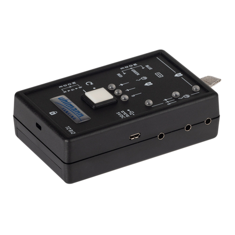
Ethos 4700 User manual

Cable Locator
Users Manual
Please read this manual before switching the unit on.
Important safety information inside.
4700


1
Contents
1 International Safety Information
2 General Description
2.1 Features
2.2 Function description
2.3 Cable Locator Mode
2.4 Specification
3 Operating Principle
3.1 Locator in complete circuits
3.2 One pole application( In open circuits)
3.3 Double pole application( In complete circuits)
3.4 Locating and tracing of lines, lateral circuit branches, sockets, switches
and junctions in house installations circuits (one-pole application)
3.5 Locating of line interruptions in the plastic-sheathed cable
(one-pole application)
3.6 Locating of line interruptions using two transmitters(one-pole application)
3.7 Error detection for a electrical floor heating (one-pole application)
3.8 Locating of bottlenecks (obstructions) in installation pipes
(single-pole application)
3.9 Locating Fuses (dual-pole application)
3.10 Locating of short-circuits in conductors (doubel-pole applicaion)
3.11 Tracing installed water and heating pipes (one-pole application)
3.12 Detedting the direction of water and heating pipes already installed
(one-pole application)
3.13 Locating a complete house wiring (one-pole application)
3.14 Following lines with higher location depth (dual-pole application)
3.15 Tracing Conductors Within the soil (single-pole application)
3.16 The reach will be improved when seeking the tension
3.17 Sorting or determination of conductors already installed
(double-pole application)
3.18 Mains Voltage Detection Locating Line Interruptions
3.19 Setting the Codes
3.20 Important Application
4 Measurement Point Illumination
5 Maintenance
6 Battery Replacement
Page
2
3
3
4
6
7
8
8
9
9
10
11
12
13
13
14
15
16
16
17
18
19
20
21
21
22
22
23
23
24
................................................................
.................................................................................
..........................................................................................
..........................................................................
...........................................................................
....................................................................................
................................................................................
................................................................
...................................................
.........................................
...............
........................................................................
....
..............
......................................................................
....................................................
................
................
......................................................................
.........................
..............
......................
..............................
..................................................................
...............................
............................................................................
......................................................................
................................................................
.........................................................................................
...............................................................................

2
1 International Safety Symbols
Warning: This symbol indicates that the operator must refer to an explanation
in the user manual to avoid personal injury or damage to the meter.
Caution! Risk of electric shock
Reference. Please use utmost attention.
Comply with EMC.
Read the user manual carefully before attempting to operate or service the meter.
The respective accident prevention regulations established by the associations
for electrical systems and equipment must be strictly met at all times.
This WARNING symbol indicates a potentially hazardous situation, which if
not avoided, could result in death or serious injury, or result damage to the
product.
This symbol advises the user that the terminal(s) so marked must not be
connected to a circuit point at which the voltage with respect to earth ground
exceeds (in this case)300 VAC or VDC.
Prior to any operation, ensure that connecting leads used and electronic load
are in perfect condition.
If the operator’s safety cannot be guaranteed, the instrument must be removed
from service and protected against use.
The Cable Locator may only be used on systems complying with the nominal
voltages indicated in the technical data section.
Prior to usage ensure perfect instrument function: we recommend to exclusively
connect the transmitter from the phase towards the neutral conductor.
If the RCD trips when connecting the sender, a fault current is already active
within the installation.
If the instrument is subjected to an extremely high electro-magnetic field, its
functioning ability may be impaired.
1 Safety Information.1
MAX
300V

3
•
•
•
•
The Cable Locator consists of a transmitter and a receiver, which is a portable
measurement instrument and can be used to detect or trace conductors.
The signal generated by the transmitter is made of a modulated current, generating
an electro-magnetic field around a conductor. This electro-magnetic field induces
a voltage within the receiving coil. The induced voltage is amplified, decoded, and
converted to the original signal by the receiver, and finally displayed on the screen.
The connecting parameter for the transmitter during an application must be a
closed current circuit.
• Finding conductors in walls, conductor interruptions, short-circuits in conductors
• Conductor tracing in the soil
• Detecting fuses and assigning current circuits
• Tracing sockets and distribution sockets having accidentally been covered by
plastering
• Detecting interruptions and short-circuits in floor heating
• Tracing metallic water and heating piping
• All application areas (both, voltage-free and live) are performed without usin
any additional instruments
• Transmitter display indicates the transmission level, the transmission code, as
well as the foreign voltage
• Receiver display indicates the reception level, the transmission code, as well
as the mains voltage detection
• Automatic and manual sensitivity adjustment
• Acoustic reception signal may be switched off
• Auto-Power-Off function
• Backlight
• Additional lighting function when working under bad lighting conditions
• Additional transmitters are available to extend or distinguish several signals
The safety can no longer be insured if the instrument:
Shows obvious damage
does not carry out the desired measurements
has been stored for too long under unfavorable conditions
has been subjected to mechanical stress during transport.
All relevant statutory regulations must be adhered to when using this instrument
2 General Description
2.1 Features:

4
2.2 Function description
+
-
Transmitter Built-in Fuses
1
2
3 LCD
4
5
6 Battery case
a
b
d
e
head on the cable.
• Insert the open cable end into connection socket 2.
Transmitter
Transmitter Display
: Terminal “ ”
: Terminal “ground”
:
: Key Sensitivity Level/Backlit
: Power Button
:
: Transmitted Code (1,2,3,4,5,6,7)
: External voltage display
c: External voltage detection
(12V, 50V, 120V, 230V, 400V)
: Low battery indication
: Transmitted level display(I, II or III)
The built-in fuses protect the instrument against overload or faulty manipulation.
The built-in fuse may only be replaced by our factory service department.
Detecting that a fuse has tripped: The reason for the output signal generated by
the transmitter being only weak could be that the fuse has tripped. To verify
whether the fuse has tripped, please proceed as follows:
• Disconnect the transmitter from all connected measurement circuits.
• Switch on the transmitter.
• Set transmission level I.
• Perform a single-pole connection of one test lead to socket 1.
• Switch on the receiver. Search for the signal at the cable and place the sensor
12
3
45
6
8
Volt
400
230
120
50
12
CODE
LEVEL
a
b
c
d
e

5
Receiver
1: Sensor head
2: Flashlight
3: LCD display
4: NCV button (Non-contact voltage detection)
to select between cable locator mode and
mains voltage detection mode
5: Flashlight button
6: Downward selection
Toggle button for manual selection of the
sensitivity
7: Mode button to selective automatic or
manual mode
8: Backlight/Beeper button
9: Upward selection
Toggle button for manual selection of the
sensitivity
10: Power ON/OFF button
11: Battery case
ON/OFF
a: The indication of the acoustic display switched off
b: The active LCD illumination indicator
c: Information transmitted by the transmitter
(transmission code and battery charge condition)
d: The indication of the automatic mode switched on
e: The signal intensity indicator with bargraph
f: Low battery indication
g: Manual mode: additional graphic display to
show the selected sensitivity Display of the
sen-sitivity within the selective mode.
Large magnifying glass => high sensitivity,
Small magnifying glass => low sensitivity
h: The manual mode active indicator
i: Mains voltage display
j: Automatic mode; digital display for signal intensity / manual mode.
k: Transmission level transmitted by the transmitter (LEVEL I, II, or III)
L: The indication of the mains voltage detection switched on
Receiver - Display
2
3
4
5
6
7
1
8
9
10
11
a
b
c
d
e
f
g
h
i
j
k
L

6
AC NCV Detection Mode
Manual Mode
Automatic Mode
2.3 Cable Locator Mode
Automatic Mode
Manual Mode (Press the MODE button)
AC NCV Detection Mode
When the automatic mode is selected the
symbol SIG is displayed.
Select Manual mode by means of “downward
selection . When the manual mode is selected
the symbol SENSE are displayed..
When press NCV button, the flashlight will
be active.
““
“
““

7
2.4 Specification
Output signal
External voltage detection
Voltage Range
Frequency Range
Display
External Voltge Detection
Over Voltage Category
Pollution Degree
Auto Power Off
Power Supply
Consumption
Fuse
(Work)
Temperature Range (Storage)
Height above MSL
Dimensions
Weight
Tracing depth
Cable Locator Mode
Voltage detection
Display
Power Supply
Consumption
Auto Power Off
Temperature Range (Work)
Temperature Range (Storage)
Height above MSL
Dimensions
Weight
Transmitter:
Receiver:
Temperature Range
125kHz
12...400V
0...60Hz
LCD display
max. 400V AC/DC
CAT III 300V
2
approx.1 hours (No any Operation )
One 9V battery , NEDA 1604, IE6F22.Power
max. 18mA
F0.5A 500V, 6.3 x 32 mm
0...40 C, max 80% rel. humidity (not condens.)
20...60 C, max 80% rel. humidity (not condens.)
up to 2000meters
130 x 69 x 32mm
approx. 130g
The tracing depth depends of medium and application
approx. 0...2meters (single-pole application)
approx. 0...0.5meters (double-pole application)
approx. 0...0.4meters
LCD with functions- and bargraph
One 9V battery , NEDA 1604, IE6F22.Power
approx. 23mA (without backlight or lamp)
approx. 35mA (with backlight)
max. 40mA (Backlight and lamp)
approx. 5minute (No any Operation )
0...40 C, max 80% rel. humidity (not condens.)
20...60 C, max 80% rel. humidity (not condens.)
up to 2000meters.
192 x 61 x 37mm
approx. 180g
°
-°
°
-°
...........................
..........................
......................
.....................................
..........
..............
.......................
........................
...........................
...........................
........................................
.......
....
....................
..............................
....................................
...........................
.................
.................
.....................
.....................................
...........................
...........................
...........................
...........................
........................
........
....
....................
..............................
....................................

8
3 Operating Principle
The Cable Locator consists of a transmitter
and a receiver. The signal generated by the
transmitter consists of a modulated current.
Generating a magnetic field around a conductor.
See figure 1. This electro-magnetic field
surrounding the conductor induces a voltage
within the receiver coils. For both automatic
and manual mode, the receiver works with
three coils and does, not depend on a position.
A selective and position-dependant search is
performed in selective mode with only one
active coil.
One-pole application: Connect the transmitter to only one conductor (one pole
application). In this operational mode, the transmitter is supplied by the built-in
battery. Due to the high-frequency signal generated by the transmitter, only one
single conductor can be located and traced. The second conductor is the ground.
This arrangement causes a high frequency current to flow through the conductor
and to be transmitted to ground, similar to a radio and receiver.
Double pole application: Connect the transmitter to the mains(double-pole
application). The transmitter is supplied by the mains. In this example, the
modulated current flows through the phase into the transformer and back through
neutral. There is a further possibility for voltage free systems by connecting the
transmitter to two line terminals while short-circuiting the other line ends. Thus
a complete circuit is created. Then, the transmitter is supplied by the built-in
battery.
The Cable Locator can only detect or locate lines, which are connected
correctly in accordance with the physical principle described.
3 1 Locator in complete circuits
Note:
.
figure 1

9
figure 2
figure 3
3.
3.
2 One pole application( In open circuits)
Note:
3 Double pole application( In complete circuits)
Note:
Line interruptions in walls and floors. Finding and tracing of lines, sockets, junction
box, switches, etc. for house installations. Finding bottlenecks, kinking and
bucklings and obstructions in installation pipes by means of a metal coil.
The ground connector must be connected to a suitable earth. A typical example
would be an earthed socket. The tracing depth amounts to 0...2 meters.
The tracing depth depends on the medium and application.
When detecting short-circuits or during wire
sorting, i.e circuits with or wihout voltage.
Voltage –free circuits are directly supplied by
the instrument battery. Example for a complete
circuit: Complete circuits are apppropriate for:
i.e. detecting sockets, switches, etc in live
installations.
The tracing depth amounts to 0...0 5 meters
The tracing depth depends of medium and
application
When connecting in live circuits, safety
regulations must be followed.
The switching with button 4 from LEVEL I to
LEVEL III the sensitvity of Distance is increased
up to factor 5.
.

10
3.
Note:
4 Locating and tracing of lines, lateral circuit branches, sockets, switches
and junctions in house installations circuits (one-pole application)
When locating and tracing of lines, sockets,
switches and junctions in house installations
circuits, the circuits must be dead; Neutral
line and ground must be connected and fully
operational; Connect transmitter to phase
and neutral according to figure 4; and Carry
out this example as described in the application
example.
If the supply cable fed with the signal via the transmitter is located, e.g. Directly
in parallel to other conductors (e.g. cable duct), or if these conductors are crossed,
the signal is also input into the other conductors. The fuse must be removed
during this example.
The switching with button 4 from “LEVEL I” to “LEVEL III” the sensitvity of Distance
is increased up to a factor of 5.
Setup: manual mode, minimal sensitivity. Tracing depth max. 2 meters.
figure 4

11
3.5 Locating of line interruptions in the plastic-sheathed cable
(one-pole application)
Note:
When locating of line interruptions, the circuit must be dead; All lines which are
not required must be connected to the auxiliary ground in accordance with figure 8;
Connect transmitter to one lead and to an neutral according to figure 5; and Carry
out this example as described in the application example.
The ground connected to the transmitter should
be earth from an earthed socket or a water
pipe which is properly earthed. When tracing
line interruptions in multicore cables, not that
all remaining leads in plastic-sheathed cable
or conductor must be grounded in accordance
with the regulations. This is required to avoid
crosscoupling of the fed signal (by a capacitive
effect to the source terminals). The tracing
depth for sheathed cable and conductors are
different, as the individual leads in the sheathed
cable are twisted around themselves. The
transition resistance of a line interruption must
be higher than 100 kOHM. The verification of
resistance can be carried out by any multimeter.
The switching with button 4 from “LEVEL I” to “LEVEL III” the sensitvity of Distance
is increased up to factor 5.
Tracing depth max. 2 meters.
Setup: manual mode, minimal sensitivity
figure 5

12
3.6 Locating of line interruptions using two transmitters
(one-pole application)
Requirements:
Note:
When locating a line interruption using one transmitter to feed from one conductor
end, the location of interruptions may not be precisely located in case of bad
conditions due to a field disturbance. The drawbacks described above can easily
be avoided when using two transmitters (one from each end) for line interruption
detection. In this instance, each of the transmitters are set to a different line code
(e.g. transmitter one to code 1 , the other transmitter to code “2“). A second
transmitter with a different line code is not included within the scope of supply
and, therefore, has to be ordered separately.
If the transmitters are connected in accordance with the figure 12, the receiver
indicates 3 at the left side of the line interruption. If you continue further than
the interruption, towards the right, the receiver displays 7 . If you are directly
above the interruption, no line code is displayed, due to the overlapping of both
transmitter signals. The line interruption is located exactly in the middle between
the displayed line codes 3 and 7
• The current circuit must not be live.
• All lines not being used must be connected to the auxiliary ground as shown in
the figure.
• Connect both transmitters as shown in the figure.
• Proceed as described in the application example.
The ground connected to the transmitter and
to the wires not being used can be as follows
is: an auxiliary ground, an orderly connected
ground contact of a home office socket, or an
orderly a grounded water pipe.
Please make sure during line interruption
locating in multi-wire shielded conductors
and cables, that all remaining wires are orderly
grounded. This is required to avoid inductive
disturbance (by capacity coupling).
The locating depth for shielded conductors and cables varies, as the individual
wires within the shield are twisted. The transition resistance of a line interruption
must be higher than 100 kOHM. The verification of resistance can be carried out
by any multimeter.
The switching with button 4 from “LEVEL I” to “LEVEL III” the sensitvity of Distance
is increased up to factor 5.
Setup: manual mode, minimal sensitivity. Tracing depth max. 2 meters.
““
““
““
““ ““.
figure 6
1
2
1
2

13
3.
3.
7 Error detection for a electrical floor heating (one-pole application)
8 Locating of bottlenecks (obstructions) in installation pipes
(single-pole application)
Note:
The connection conditions:
If a shield mat or shield wiring is located
above the heating wires, no ground connection
may exist. If required, separate the shield
from the ground connection.
The switching with button 4 from “LEVEL
I” to “LEVEL III” the sensitvity of Distance
is increased up to a factor of 5.
A second transmitter is required for this
application.
Setup: manual mode, minimal sensitivity.
Tracing depth max. 2 meters.
When locating of bottlenecks in installation
pipes, Any circuits in the pipe must be dead
and grounded; Connect transmitter to the
metal coil and auxiliary ground according to
figure 8; and Carry out this example as
described in the application example.
If you have only coil actual of non conducting material (ex. fiber), we recommand
you to slide a copper wire ex. 1 5mm up to the x-pipes.
The switching with button 4 from “LEVEL I” to “LEVEL III” the sensitvity of Distance
is increased up to a factor of 5.
Setup: manual mode, minimal sensitivity. Tracing depth max. 2 meters.
•
•
•
•
.2
1
2
1
2
figure 7
figure 8

14
3.9 Locating Fuses (dual-pole application)
Note: Set transmitter to LEVEL I
°
When connecting in live circuits, the safety directions must absolutely be
respected.
Insert into the current circuit of a multifamily
residential structure within a socket between
L1 and N and switch the transmitter to LEVEL I .
You may assign the signal in the secondary
distribution and main distribution by transmitter
pre-setting LEVEL I . Thus, fuses and automatic
devices can definitely be assigned to a certain
current circuit. The detection or assignment
of the fuse strongly depends on the wiring
realised within the distribution. To obtain a
result as precise as possible, the cover should
be removed and the supply line to the fuse
should be traced.
The switching with button 4 from LEVEL I to LEVEL III“ the sensitvity of Distance
is increased up to s factor of 5.
Setup: selective mode, minimal sensitivity
Safety cut-outs of different manufacturers have different installation positions for
magnetic coils. If no evident signal can be found by the receiver in the position
shown below it is advised to modify the position by 90 towards the left or the
right.
““
““
“““
figure 9

15
3.10 Locating of short-circuits in conductors (double-pole application)
Note:
When locating of shrot-circuits in conductors,
any existing circuits within the cable must be
voltage-free; connect transmitter in accordance
with Figure 10; and carry out this example as
described in the application example.
Note that the tracing depth for sheathed cable
and conductors are different due to the fact
that the individual leads in the sheathed cable
are twisted around themselves. Usually,
short-circuits can only be correctly detected
when the short-circuit resistance is lower than
20 Ohm. The verification of the short-circuit
resistance can be carried out with any multimeter.
Should the short-circuit resistance amount to more than 20 Ohm, you can try
the experiment to detect the error location by means of the line interruption
mehtode. You can try with sufficient energy to determine the error location (low
ohmic connection) or to burn it in a way ensuring a line interruption.
The switching with button 4 from “LEVEL I” to “LEVEL III” the sensitvity of
Distance is increased up to a factor of 5.
Setup: manual mode, minimal sensitivity. Tracing depth max. 0,5 meters.
figure 10

16
3.11
3.12
Tracing installed water and heating pipes (one-pole application)
Detecting the direction of water and heating pipes already installed
(one-pole application)
Note:
The tracing conditions: The line to be located must be separated from the
equipotential bonding.
For safety reasons the electrical system must not be live!
Connect transmitter at foundation ground to
the ground socket. The second transmitter
socket has to be connected to the conductor
to be located. Now the feed line can be traced.
The switching with button 4 from “LEVEL I”
to “LEVEL III” the sensitivity of Distance is
increased up to a factor of 5.
Setup: manual mode, minimal sensitivity.
Tracing depth max. 2 meters.
When detecting the direction of water and
heating pipes already installed, the respective
water and heating pipes must be suitably
grounded; connect the transmitter according
figure 12; and carry out this example as
described in the application example.
The earth of a properly earthed socket is a suitable ground. The switching with
button 4 from “LEVEL I” to “LEVEL III” the sensitivity of Distance is increased up
to a factor of 5.
Setup: manual mode, minimal sensitivity. Tracing depth max. 2 5 meters..
figure 11
figure 12

17
3.13 Locating a complete house wiring (one-pole application)
Note:
In order to determine all electrical lines of a house within one working process,
proceed as follows:
Remove the bridge in the main distribution
between PE and N .
• Connect the transmitter to the system
compliance with the figure 13. Now, the
neutral conductor, being present within the
total system, may be followed.
For safety reasons, the system must not
be live!
The switching with button 4 from “LEVEL I” to “LEVEL III” the sensitvity of
Distance is increased up to a factor of 5.
Setup: manual mode, minimal sensitivity. Tracing depth max. 2 meters.
•
““ ““
figure 13

18
3.14 Following lines with higher location depth (dual-pole application)
Note:
If the dual-pole application is carried out on multi-wire cables, the location depth
is widely limited. The reason is that the go-and-return lines are installed very closely.
Thus, a strong distortion of the magnetic field occurs. The electro-magnetic field
may not develop at the bottleneck. This limitation can easily be eliminated when
using a separate conductor to simulate the return line. This separate conductor
allevel is a larger spreading of the electro-magnetic field. Any conductor or cable
reel can be used as separate return conductor.
When tracing the conductors, special care has to be taken that the distance between
go-and-return-line is larger than the location depth. In practical applications, this
amounts to approx. 2.0 meters..
For this application, humid walls, plaster, etc.have only an insignificant influence
on the location depth
• The current circuit must not be live.
• Connect the transmitter in compliance with
the figure 14.
• The distance between go-and-return line
must be minimum 2.0 meters to 2.5 meters
or more.
• Proceed as described in the application
example.
The switching with button 4 from “LEVEL I” to > 2m “LEVEL III” the sensitvity
of Distance is increased up to a factor of 5.
Setup: manual mode, minimal sensitivity. Tracing depth max. 2.5 meters.
figure 14
Table of contents
Other Ethos Measuring Instrument manuals

