ETI NETCOM ADH NEMA Use and care manual

MODEL ADH NEMA
ADH NETCOM AC NEMA AUTOMATIC AIR DEHYDRATOR
HUMIDITY SENSOR ASSEMBLY REPLACEMENT PROCEDURE
Replacement Kit Part Number 24092
Document Part Number 24105

HUMIDITY SENSOR ASSEMBLY
REPLACEMENT PROCEDURE
MODEL ADH NEMA
Lethal Voltages Present
Lethal voltages are present inside the ADH
NETCOM. Service should be performed by
qualified personnel only. There are no user
serviceable components inside the chassis.
Abnormal Odor or Smoke
In the event of smoke or a burning or abnormal
odor, immediately interrupt power to the ADH
NETCOM with the POWER switch at the rear of the
unit, unplug the unit, or turn off the circuit breaker
controlling the outlet. Note that only the AC model
of the ADH NETCOM has an ON / OFF switch.
Pneumatics
Each of the air pumps inside the ADH NETCOM
automatic air dehydrator is capable of generating
as much as 24 psig (1,655mbar). Other attached
dry air sources may be capable of generating even
higher pressures. Proper safety practice requires
treating all pneumatic components with care.
Always vent the system to atmospheric pressure
before servicing pneumatic components.
Rack Mounting
Before and after rack mounting the ADH
NETCOM, ensure that the rack is stable. Mounting
of the ADH NETCOM into a rack should be such
that a hazardous condition is not created due to
uneven mechanical loading. Verify that adequate
air flow and power source capacity is available to
the unit. Ensure that the ADH NETCOM maximum
operating temperature of 130°F (55°C) will not be
compromised by other components in the rack.
Ensure reliable earthing of the ADH NETCOM.
ADH NETCOM AC NEMA HUMIDITY SENSOR ASSEMBLY
REPLACEMENT PROCEDURE
This procedure addresses the removal and replacement of
the Humidity Sensor Assembly in an ADH NETCOM AC
NEMA Automatic Air Dehydrator. It is recommended to read
the entire procedure prior to beginning work.
INVENTORY LIST
Identify the following items in this kit prior to beginning
work.
TOOLS REQUIRED
The following tools are needed to perform this procedure:
• Small flat blade screwdriver
• Tubing wrench or vacuum tube pliers
• Diagonal Cutters
• Long screwdriver
NOTE :
On AC units, it might be useful to move the power filter
module and switch assembly out of the way for better access
to the humidity sensor during this procedure. Refer to Figure
1a. To do so, from the inside of the machine, after first noting
their placement, carefully disconnect the three electrical
leads from the filter module. Do not separate the leads from
the spade lugs. Then, from the back of the machine, unscrew
the two screws securing the power filter module to the
machine chassis then gently push the power filter module
toward the back of the dehydrator. It is not necessary to fully
remove the power filter module.
2
PART NO. DESCRIPTIONQTY.
23707
24105
SENSOR/TERMINAL BLOCK ASSEMBLY
Instruction Manual (this document)
1
1
HUMIDITY SENSOR ASSEMBLY REPLACEMENT PROCEDURE | PART NO. 24105 REV B.0
ETI’s two year limited warranty covering defects in workmanship and materials applies.
Contact Customer Service for complete warranty information.
LIMITED WARRANTY
ETI makes no representations or warranties, either expressed or implied, with respect to the
contents of this publication or the products that it describes, and specifically disclaims any
implied warranties of merchantability or fitness for any particular purpose. ETI reserves the
right to revise this publication, and to make changes and improvements to the products
described in this publication, without the obligation of ETI to notify any person or
organization of such revisions, changes or improvements.
DISCLAIMER

3
Shut off machine power by unplugging the unit.
Open the two front door latches, loosen the two captive
screws in the corners of the housing opposite the hinges,
then open the NEMA box. Place an object underneath the
door once open to help support it during this procedure.
Remove the orange Ethernet cable on the left by
disconnecting both ends, then removing it. Set aside for
re-use. Remove the power cable connector on the right by
loosening the captive screw on each end of the green
connector, then unplugging the connector. Disconnect the
ground wire by loosening the ground wire retaining screw,
then carefully removing the ground wire. Refer to Figure 1.
To replace the Humidity Sensor Assembly (23368) in either an
ADH NETCOM Automatic Air Dehydrator with AC power or an
ADH NETCOM with Redundant DC power, perform the steps
below. Refer to Figure 1a or 1b, respectively, for AC and DC unit
illustrations.
HUMIDITY SENSOR ASSEMBLY REMOVAL AND
REPLACEMENT
1.
2.
3.
Remove and retain the four mounting screws from the
four corners of the protective front cover, then slowly lift
the front cover, carefully flip it over, then set it down,
upside down, to rest on the inside of the enclosure door.
Be careful as there are still many wires connected
between the enclosure and the front cover and there isn’t
a lot of slack. Note that the two upper front cover
mounting screws are located in plain sight in the top
corners of the front cover, while the two lower front cover
corner mounting screws are located down in the front
“well” of the unit. Use a long-handled screwdriver to
remove them.
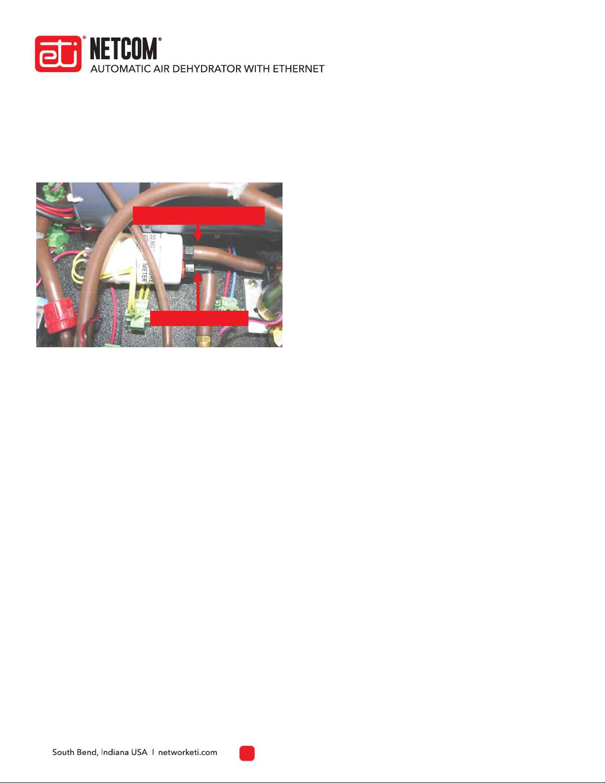
For greater access during this procedure, disconnect the
“Y” hose assembly at the point of the outlet port as shown
in Figure 2.
4.
5.
Disconnect the humidity sensor terminal block from the
electrical connector by loosening the captive screw at
either end of the connector then disconnecting the
terminal block. Refer to Figure 3.
6.
Disconnect both ends, then remove
orange Ethernet cable.
Loosen both captive
screws, then disconnect
connector.
Loosen screw, then remove
ground wire.
Figure 1. DISCONNECTING THE ETHERNET CABLE,
THE POWER CABLE CONNECTOR, AND THE GROUND WIRE.
HUMIDITY SENSOR ASSEMBLY REPLACEMENT PROCEDURE | PART NO. 24105 REV B.0
HUMIDITY SENSOR ASSEMBLY
REPLACEMENT PROCEDURE
MODEL ADH NEMA
Disconnect the “Y” hose
assembly here.
Humidity Sensor Assembly
Figure 2. “Y” HOSE ASSEMBLY DISCONNECT POINT.
Figure 3. THE ADH NETCOM AC NEMA AUTOMATIC AIR
DEHYDRATOR HUMIDITY SENSOR ASSEMBLY AND ELECTRICAL CONNECTOR.
Humidity Sensor Assembly
Humidity sensor
electrical connector
For technical help, questions or comments concerning this
product or any ETI product contact Customer Service 8:00 a.m.
- 5:00 p.m. Eastern Time.
networketi.com
ETI
1850 North Sheridan Street
South Bend, IN 46628
Email:
Web:
Mail:
CONTACTING CUSTOMER SERVICE
4
Using a tubing wrench or vacuum tubing pliers, carefully
remove the two air hoses connected to the existing
humidity sensor. Try to not move the fittings or break the
seal. Refer to Figure 4.
7.
Using the diagonal cutters, cut the two tie wraps
securing the humidity sensor assembly to the two tie
wrap mounts.
Once both air hoses and the terminal block have been
disconnected and the two tie wraps have been cut,
remove the existing humidity sensor from the
dehydrator.
Place the new humidity sensor onto the two tie wrap
mounts from which the original assembly was removed.
Rotate the sensor on the two mounts so that the two air
hoses reach their respective 90° and straight fittings, just
as they were on the original assembly. The Air Out hose
connects to the straight fitting. The Air In hose connects
to the 90° fitting. There is no right or wrong angle for the
humidity sensor itself in terms of its function. All that
matters is that each air hose connects securely to its
respective fitting. Do not yet apply the tie wraps.
Install the new humidity sensor terminal block to the
electrical connector which was removed in step 6.
Tighten the two captive end screws to secure the
terminal block in place.
Once the rotation of the humidity sensor is determined
based on the position of the hoses to the fittings, secure
the new humidity sensor assembly in place by feeding
the two tie wraps from the kit through the slot in each
mount, knurled side up. Tighten the tie wraps, then cut
off the excess from each one.
8.
9.
10.
11.
12.
Reconnect the “Y” section of the tubing assembly,
disconnected in step 5, to the outlet port fitting.
Reinstall the front cover removed in step 4 of this section.
If it was placed upside down on the lid of the unit during
this procedure, carefully turn the cover back over and
work it back into position, past the wires and other
components in the enclosure. Reinstall the four corner
screws securing the front cover to the chassis.
Reconnect the ground wire by inserting it behind the
retaining screw from which it was removed in step 3, then
tighten the ground wire retaining screw. Connect the
terminal block to the power connector by holding it in
place then tightening the two captive screws. Reconnect
both ends of the orange Ethernet cable removed in step 3
of this section. It does not matter which end of the
Ethernet cable goes into which receptacle.
With the ground wire, power connector and Ethernet
cable reconnected, close the lid of the NEMA enclosure
and secure the two latches opposite the hinges. Secure
the lid in place by reinstalling the two captive screws in the
two outer corners of the lid.
13.
14.
15.
16.
HUMIDITY SENSOR ASSEMBLY REPLACEMENT PROCEDURE | PART NO. 24105 REV B.0
HUMIDITY SENSOR ASSEMBLY
REPLACEMENT PROCEDURE
MODEL ADH NEMA
Air Out hose (straight fitting)
Air In hose (90° fitting)
Figure 4. THE TWO HUMIDITY SENSOR AIR HOSES.
This manual suits for next models
1
Other ETI Accessories manuals


