ETI SNOW SWITCH HSC-24 User manual

South Bend, Indiana USA | networketi.com DEICING CONTROLLER INSTALLATION MANUAL | PART NO. 25123 REV 0.0
DESCRIPTION
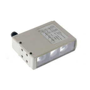
The Snow Switch Model HSC-24, 24-volt Pavement-Mounted Snow
and Ice Sensor reliably detects snow and ice conditions on pavement
surfaces. The HSC-24 pavement sensor ensures that deicing heaters
operate only while needed which minimizes energy costs without
sacricing snow melting effectiveness.
The HSC-24 is designed to be self-contained eliminating the need for
an additional control panel, and it’s independent relay-contact output is
compatible with most heater control systems.
As part of a snow melting system, the HSC–24 sensor will signal for snow
and ice melting at pavement temperatures below 38°F (3.3°C) while
moisture in any form—including water, snow, sleet or ice—is present.
MODEL HSC-24
PAVEMENT-MOUNTED SNOW AND ICE SENSOR

South Bend, Indiana USA | networketi.com DEICING CONTROLLER INSTALLATION MANUAL | PART NO. 25123 REV 0.0
2
It’s important for the sensor to be level with the pavement
surrounding it. A Pavement Sensor Housing, ETI part
number 23832 (sold separately), is needed for each
pavement sensor. This housing supports the sensor within
the pavement and includes adjustment screws that allow
proper leveling with the pavement surface.
WHAT’S IN THE BOX
Immediately upon receipt, inspect the container and packing
material for any noticeable damage or missing contents.
From the factory an HSC–24 sensor includes:
1-HSC–24 pavement sensor (PN 25124)
1-Package (1 lb.) duct seal (PN 20763)
3-3/8”-16 × 0.25” hex socket set screws (PN 21630)
3-#8-32 × 0.375” machine screws (PN 11632)
1-3/16” hex key (PN 21631)
1- Installation and Operation Manual (PN 25123)
Unpack the unit, taking care not to damage the packing
materials. Save the shipping container and related
materials until normal operation has been established. In
the event of shipping damage, keep the packing materials
for inspection by the carrier. If any of the contents are
missing or damaged please contact your supplier or ETI
Customer Service.
SENSOR LOCATION
The HSC–24 pavement sensor should be installed in
a location that best represents the typical snow and
ice conditions on the pavement surfaces that are
being deiced.
Position the sensor centered between the heater cables
or tubing. This will allow the sensor to be exposed to a
surface temperature that is typical of the deiced area
without causing abnormal heating of the sensor.
AVOID: BUILDING OVERHANGS, TREES, LOCATIONS
WHERE VEHICLES PARK AND ANY OTHER
OBSTRUCTIONS THAT MAY PREVENT SNOW,
FREEZING PRECIPITATION AND/OR SOLAR
GAIN FROM REACHING THE SENSOR.
AVOID: HOT AIR EXHAUST DUCTS OR OTHER HEAT
SOURCES THAT MAY AFFECT THE SENSOR
AND CAUSE IT TO BE WARMER AND DRIER
THAN THE AREA BEING DEICED.
AVOID: EXPOSURE TO ARTIFICIAL HEAT SOURCES AND
ANIMALS. A SENSOR INSTALLED IN AN AREA
HOUSING ANIMALS (SUCH AS A KENNEL)
OR IN AN AREA WITH A HIGH AMOUNT OF
ANIMAL TRAFFIC MAY RUN MORE OFTEN
THAN DESIRED.
CONSIDER: SITE DRAINAGE IS IMPORTANT. A SENSOR
PLACED IN A LOCATION WHERE THE
DRAINAGE IS BETTER OR WORSE THAN IS
TYPICAL OF THE PAVEMENT INSTALLATION
MAY CAUSE THE SYSTEM TO TURN OFF TOO
SOON OR TO RUN TOO LONG.
CONSIDER: VEHICLE AND PEDESTRIAN TRAFFIC MAY
TRACK MOISTURE AND WET DEBRIS ONTO
THE PAVEMENT SENSOR AND CAUSE THE
SYSTEM TO RUN LONGER. DEPENDING ON
THE FUNCTION OF THE AREA BEING DEICED IT
MAY OR MAY NOT BE DESIRABLE TO EXPOSE
THE SENSOR TO TYPICAL TRAFFIC PATTERNS.
CONSIDER: INSTALLING ADDITIONAL SENSOR HOUSINGS,
IT IS LESS EXPENSIVE THAN DIGGING UP A
PAVEMENT INSTALLATION LATER. INSTALLING
ONE OR MORE EXTRA HOUSINGS WILLALLOW
YOU TO MOVE A SENSOR LATER IF NEEDED.
ALSO, DEPENDING ON THE CONTROL BEING
USED, YOU MAY BE ABLE TO RUN ADDITIONAL
SENSORS TO THE SAME CONTROL.

South Bend, Indiana USA | networketi.com DEICING CONTROLLER INSTALLATION MANUAL | PART NO. 25123 REV 0.0
3
CONDUIT
After positioning the sensor, install 3/4” conduit from the
sensor housing to the snow melting control. Do not share
the sensor cable’s conduit with any high voltage wiring.
The HSC–24 pavement sensor includes 60’ (18 m) of cable.
Should any additional length of cable be required, ensure
that the splice is made in a junction box appropriate for
the location.
HOUSING INSTALLATION
Follow the instructions in the Pavement Sensor Housing
manual to ensure the housing is installed correctly and
made level with the paving surface.
SENSOR INSTALLATION
Remove the sensor housing cap from the housing unit by
removing the three screws securing it in place. Be sure to
keep the cap for future use should the housing unit need
to be recapped.
Feed your sh tape through the conduit from the control
end. Attach the cable to the sh tape and pull it back
through the conduit, using cable lubricant if necessary.
Be sure there are no kinks in the cable. Leave a few inches
of cable at the pavement sensor end for a service loop.
Inside the Pavement Sensor Housing apply duct sealant
to protect the installation, leaving room for the sensor to
be placed down inside the housing. Knead the supplied
duct sealant until it is pliable. In addition to sealing the
wiring conduit, the duct sealant should occupy space in
the housing so that it will displace water that might enter.
This will minimize the accumulation of water and ice in the
housing and protect against possible ice damage.
Install the sensor into the housing with its top resting on
the top of the Height Adjustment Ring. Check that all
six holes are properly aligned, and fasten the sensor
to the Height Adjustment Ring with the three Sensor
Retaining Screws.
To promote correct assembly the screws that secure the
housing cap and sensor attachment are positioned to
form the points of an equilateral triangle. The positions of
the height adjustment screws, which level the surface of
the sensor to the surface of the pavement, form the points
of an isosceles triangle.
Adjust sensor to be ush with the pavement around it. To
do this remove the three protective hex screws (Figure
2), when removed you will see the Height Adjustment
Screws. To level the sensor rotate the Height Adjustment
Screws (Figure 3) clockwise to lower the sensor or
counterclockwise to raise it. The housing ange can be
raised up to 0.63”(16 mm) to allow the sensor surface to
be aligned with the pavement surface. When the unit is
level and ush with the pavement, reinstall the protective
hex screws. Failing to level the sensor ush with its
surrounding pavement can result in water pooling which
will cause the sensor to not function properly.

South Bend, Indiana USA | networketi.com DEICING CONTROLLER INSTALLATION MANUAL | PART NO. 25123 REV 0.0
4
FIGURE 1. HSC-24 Pavement Sensor Installation.
FIGURE 2. Remove protective hex screw to reveal Height
Adjustment Screw.
FIGURE 3. Rotate Height Adjustment Screw clockwise to
lower or counterclockwise to raise sensor.

South Bend, Indiana USA | networketi.com DEICING CONTROLLER INSTALLATION MANUAL | PART NO. 25123 REV 0.0
5
FIGURE 6. Wire connections for dry contact control.
FIGURE 4. Wire connections for 24 ac loads.
FIGURE 5. Wire connections for external relay with 24 ac coil.

South Bend, Indiana USA | networketi.com DEICING CONTROLLER INSTALLATION MANUAL | PART NO. 25123 REV 0.0
6
WIRING
Be sure to follow NEC and local code for all electrical
connections.
A four-conductor direct-burial wet-environment cable
is required to connect the HSC-24 sensor to the control
panel. The 60-foot cable supplied with the HSC-24 meets
these requirements. This may be extended up to 500 feet
(152m) using 18 AWG 4-wire jacketed cable, or up to
2,000 feet (609m) using 12 AWG 4-wire jacketed cable.
Install all cables through conduit as indicated in the
Conduit section.
Make sure that any cable runs greater than 60 feet are
spliced together either in a suitable water-tight junction
box or in some other water-tight or dry location.
Cable Connections for HSC-24 Snow Switch Pavement
Sensor:
WIRE COLOR FUNCTION
BLACK Ground
RED 24 V Power (AC or full-wave rectied)
BLUE Sensor Output Signal
ORANGE Sensor Output Signal
The HSC-24 can directly operate solenoids, pumps, or
other loads up to a maximum of 60 W or 62 VA.
For applications of this type that operate at 24 V ac, see
Figure 4.
For larger loads, the HSC-24 can operate a separate
relay or contactor. Figure 5 shows the connections for an
external relay with a 24 V ac coil.
Boiler controllers often need a dry contact closure
to control their operation. The wiring for this type of
connection is shown in Figure 6.
TESTING
The sensor installation should be tested before being
placed in service. The HSC-24 has an internal self-test
mode which can be used to help verify correct operation.
A Digital Volt Meter (DVM) is used to test its operation.
1. Verify the supply voltage to the sensor. With the system
turned on, measure the voltage from the sensor’s
black lead to the red lead. By measuring with an AC
range setting and then with a DC range setting, each
type of voltage will be shown on the DVM. Depending
on the controller used, the DVM readings should be
11-12 VAC and 24-28 VDC (with rectied source), 22-
28 VAC and 0 VDC (with pure ac source), or 0 VAC and
22-26 VDC (with pulsed DC source).
2. Meter Connections for Self Test
During self test, the sensor’s internal heater can be
tested using the DVM as a current meter. The sensor
current is measured with the DVM connected in series
with the sensor power lead (the red wire). The meter
can be set to DC amps when the sensor is being
powered by a functioning ETI control panel. It can
be set to AC amps when the unit is powered with a
separate 24 VAC power supply. When the heater is
off, the current will be about 5 mA. When the heater is
on, the current will be about 250 mA.
During self test, the sensor’s output signal can be
tested with a voltmeter while the output lead is
connected to a functioning control panel. The voltage
is measured from the Blue lead to the Orange lead.
When the temperature is above 38°F or the sensor is
dry, the output will be OFF. In this case there will be a
voltage present from Blue to Orange (the voltage will
depend on the system controller).
To call for heat, the blue and orange wires are
connected together by the sensor’s internal
relay. These wires are interchangeable.
NOTE:

South Bend, Indiana USA | networketi.com DEICING CONTROLLER INSTALLATION MANUAL | PART NO. 25123 REV 0.0
7
When the output is turned ON, the voltage from Blue
to Orange will be zero volts.
The sensor can also be tested with at least one of
the Blue and Orange leads disconnected, using the
continuity-test mode on the DVM. When the output is
OFF, Blue and Orange will be open; when the output
is ON, they will have continuity.
3. After the meter connection is made,initiate the self-test
mode as follows. A system power switch or temporary
connection for the red power lead is needed to allow
briey interrupting the supply voltage to the sensor.
See Figure 5.
a. Power is applied to the sensor.
b. Then between 0.1 second and 4 seconds later,
the power is very briey interrupted – for 50 to
100 milliseconds – and then reapplied. This can be
done with a power switch, using a clip cable, or by
temporarily wiring a normally-closed pushbutton
so that it can be very briey pressed.
c. The power is maintained after that power-up pulse,
and the self-test then begins.
The self-test mode can be identied by the initial
increase in current draw (part 5a, below). If that
does not happen, it may be that self-test mode was
not entered; this happens if the power-off pulse
time is too long. In that case, remove power for at
least two seconds, then repeat the off-pulse
sequence (a-c) described above (Figure 7).
4. After the self-test mode is initiated, the following
action will happen:
a. The heater turns on for three seconds. During this
time, the current draw will increase to 0.25 amps.
This can be monitored with the current meter as
described in part 2.
b. As shown in Figure 7, the output and heater
temperature, measured to the nearest degree F.
One pulse means below 38, 2 means at 38, 3
means above 38, 4 means there is a problem.
c. After that, the unit will go into moisture-sense
mode. At this point, when moisture is sensed, the
output will turn on. When moisture is not sensed,
the output will turn off. This is monitored with the
DVM as described in part 2.
d. Moisture can be simulated with water on the sensor
(at any temperature) or with a metallic object
placed on the sensor to short one of the electrode
disks to the outside rim of the sensor.
When moisture is sensed, in addition to the output
turning on, the heater will begin pulsing with one
second on and two seconds off. You can see that
happening with the current meter.
e. After one minute, the self-test will end, and the
sensor will begin normal operation.
5. As an alternative to the self-test mode, the sensor can
be tested with ice. To do this, place ten pounds (4.54
kg) of crushed ice over the sensor and wait about 20
minutes before observing that a low output voltage (2
volts or less) is indicated by the DVM.When the sensor
temperature goes below 38° F (3.3° C) the sensor’s
output will turn ON and change to a lower voltage. If
the sensor surface temperature is initially very warm
then this procedure may take longer, perhaps 40
minutes or more.
6. With satisfactory results, disconnect the DVM and
restore all sensor wiring connections.

South Bend, Indiana USA | networketi.com DEICING CONTROLLER INSTALLATION MANUAL | PART NO. 25123 REV 0.0
8
HOLD-ON TIME DISPLAY
The programmed hold time can be determined with this
test. Using the sensor and meters connected as in the self-
test mode (“Testing” section 2), apply power to the sensor
and within four seconds quickly interrupt and restore the
power twice. After a two second delay, the unit will pulse
both the heater and output (one second on, one second
off) n+1 times to indicate the currently congured hold-
on time. This will be repeated 5 times with 3 seconds
between each set of pulses. See Figure 8.
FIGURE 7. Sensor Self-Test Mode.
FIGURE 8. Hold-On Time Display Mode.

South Bend, Indiana USA | networketi.com DEICING CONTROLLER INSTALLATION MANUAL | PART NO. 25123 REV 0.0
9
HOLD-ON TIME CONFIGURATION
The programmed hold time can be changed with this
procedure. Apply power to the sensor and within four
seconds quickly interrupt and restore the power three
times. After a two second delay, the sensor will send three
quick pulses to indicate it is in hold-on conguration
mode. Interrupt and reapply power to create n+1 quick
pulses to zero volts, where n is the number of hours
(from 0 to 6 hours, 1 to 7 pulses). See Figure 9. The rst
pulse must be within 6 seconds or the process aborts.
There can be up to two seconds between pulses. After
conguring the hold-on time, wait two seconds to initiate
a save of the hold-on time. Once the hold-on time has
been saved the sensor will display the new hold-on time
with the same pattern used during the hold-on time
display mode (Figure 8).
FIGURE 9. Hold-On Time Conguration Mode.
TROUBLESHOOTING
Most issues are due to wiring error or moisture in the
housing. Check for these issues rst. If problem persists
please contact your supplier or ETI Customer Service.
MAINTENANCE
The top of the sensor should be kept reasonably clean
and free of gravel, leaves, mud, or other debris. If paving
material, salt or another residue becomes adhered to the
sensing elements, clean the surface with a Scotch™ Brite
Pad. Do not use metallic or coarse abrasives or detergents.
We recommend that the HSC-24 sensor’s power supply
operate continuously even though you may elect to de-
energize the snow/ice melting system main heaters at the
season’s end. The sensor will consume very little energy
(a small fraction of a watt) and this will enhance the long-
term reliability of the HSC-24 sensor.
RETURNS AND REPLACEMENTS
Equipment cannot be returned for credit once it has
been installed. Environmental Technology will repair or
replace faulty equipment under warranty. Prior to removal
of equipment for warranty return, please contact ETI
Technical Support at for troubleshooting assistance.
Before returning a unit to ETI,obtain a Return Merchandise
Authorization from our Customer Service Department,
available between 8:00 a.m. and 5:00 p.m. Eastern Time. If
possible, use the original container and packing materials
when packing the unit for shipment. It is important to
mark the Return Merchandise Authorization clearly
on the outside of the shipping container so that it may
be correctly processed upon receipt at Environmental
Technology.

South Bend, Indiana USA | networketi.com DEICING CONTROLLER INSTALLATION MANUAL | PART NO. 25123 REV 0.0
10
SPECIFICATIONS
General
Area of Use Pavement
Activation Temperature 38˚ F (3.3˚ C)
Hold-on Time User congurable to 0 h, 1 h, 2 h, 3 h, 4 h, 5 h, or 6 h
Default Hold-On Time 0 h up to 3 minutes after snow/ice/water no longer detected or
5 minutes after temperature rises above sense range
Materials Brass with Epoxy and Polyurethane Fill
Weight 0.5 kg (1.1 lb)
Dimensions Top Diameter: 9.84 cm (3.875 in)
Top Thickness: 6.35 mm (0.25 in)
Mounting Depth: 5 cm (2 in)
Electrical
Circuit type NEC Class 2
Supply voltage 24 Vac +/- 15%
Supply Current 5 mA idle, 0.25 A max.
Operating Power 6 W max.
Snow/Ice Sense Response Time 10 to 20 seconds
Output Signal Voltage drop
Output Off Relay Open
Output On (snow/ice present) Relay Closed
Contact Rating 220 Vdc / 250 Vac / 2 A / 60 W / 62 VA max.
Cable Type Direct Burial 4-Conductor 18 AWG
Cable Length 60 ft (18.3 m) included; may be extended:
• Up to 500’ (152m) using 18 AWG 3-wire jacketed cable
• Up to 2,000’ (609m) using 12 AWG 3-wire jacketed cable
Self Test Mode Checks temperature, heater, and sensor grid. Indicates results with output
and current pulses (see manual).
Compatible Controllers APS , EUR, PD Pro, and GF Pro controllers, and other systems which can utilize
contact-closure signaling and provide 24 Vac power.
Environmental
Operating Temperature Range −40 °C to 70 °C (−40 °F to 158 °F)
Snow/Ice Sense Temperature Range −30 °C to 3 °C (−22 °F to 38 °F)
Storage temperature −50°F to 180°F (−45°C to 82°C)

South Bend, Indiana USA | networketi.com DEICING CONTROLLER INSTALLATION MANUAL | PART NO. 25123 REV 0.0
11
ORDERING INFORMATION
ORDER# DESCRIPTION
25125 HSC–24 Pavement-Mounted Sensor
(requires Pavement Sensor Housing)
23832 Pavement Sensor Housing
CONTACT CUSTOMER SERVICE
For assistance, contact Customer Service. Ofce hours are
from 8:00 AM until 5:00 PM ET.
Email: [email protected]
Web: networketi.com
Mail: ETI
1850 North Sheridan Street
South Bend, IN 46628
LIMITED WARRANTY
ETI’s two year limited warranty covering defects in
workmanship and materials applies. Contact Customer
Service for complete warranty information.
DISCLAIMER
ETI makes no representations or warranties, either
expressed or implied, with respect to the contents
of this publication or the products that it describes,
and specically disclaims any implied warranties of
merchantability or tness for any particular purpose. ETI
reserves the right to revise this publication, and to make
changes and improvements to the products described
in this publication, without the obligation of ETI to notify
any person or organization of such revisions, changes or
improvements.
Copyright © 2019 ETI,
®
All rights reserved.
Table of contents
Other ETI Accessories manuals


